1
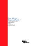
User Manual
Multi Display EX (MEX)
JH 19T02 MEX - 19.0 inch Multi Display EX
Jakob Hatteland Display AS
Åmsosen, N-5578 Nedre Vats, Norway
Phone: +47 5276 3700, Fax: +47 5276 5444
www.hatteland.com
User Manual JH 19T02 MEX
Updated: 20 Apr 2005
Doc Id: INB100016-1 (Rev 1)
For models: (and some variations)
-A2
Copyright © 2005 Jakob Hatteland Display AS
Aamsosen
N-5578 Nedre Vats, Norway
Information in this manual are copyrighted to the respective owners. All rights are reserved by Jakob
Hatteland Display AS. This information may not, in whole or in part, be copied, photocopied, reproduced,
translated or reduced to any electronic medium or machine-readable form without the prior written consent
of Jakob Hatteland Display AS.
The products described, or referenced, herein are copyrighted to the respective owners.
The products may not be copied or duplicated in any way. This documentation contains proprietary
information that is not to be disclosed to persons outside the user’s company without prior written consent
of Jakob Hatteland Display AS.
The copyright notice appearing above is included to provide statutory protection in the event of
unauthorized or unintentional public disclosure.
All other product names or trademarks are properties of their respective owners !
Contents
Contents........................................................................................ 3
General .......................................................................................... 7
Introduction to Jakob Hatteland Display AS
About this manual
Basic Construction - Maritime Multi Display
7
8
9
General Installation Recommendations................................... 10
Installation and mounting
Ergonomics
Cables
Cable Entries & Connectors (Marked area) - Illustration only
Maximum Cable Length
General Safety / Acceptance instructions
Repair / Warranty
Physical Connections - JH 19T02 MEX
Pin Assignments - Common Connectors
10
10
12
12
12
13
13
14
16
User Controls ............................................................................. 20
Operation
OSD Menu Overview
OSD Menu Functions
Preset Signal Timings SXGA displays (DVI)
20
22
24
29
Specifications ............................................................................. 31
Specifications - JH 19T02 MEX
32
Technical Drawings.................................................................... 33
Technical Drawings - JH 19T02 MEX
Standard Version
34
34
General - Appendix .................................................................... 35
Testing & Approvals Overview
Declaration of Conformity
Basic Trouble-shooting
Return Of Goods Information
Terms
Revision History
36
37
38
39
40
44
Contact Information ................................................................... 46
3
IND100130-12
INB100016-1 (Rev 1)
4
INB100016-1 (Rev 1)
General
5
INB100016-1 (Rev 1)
6
Jakob Hatteland Display AS
KNOWLEDGE - QUALITY - ECONOMY
Introduction to Jakob Hatteland Display AS
Founded in 1987, Jakob Hatteland Display (JHD), based in Norway, offers the widest range of
type approved marine monitors, panel computers and type approved marine computers for the
worldwide commercial, naval, yacht and cruise market.
Today the group develops and manufactures a complete range of IEC 60945 tested marine
monitors, panel computers and IEC 60945 tested marine computers.
Approved Marine Displays (MMD/STD)
Hatteland Display’s marine monitors are based on high quality and state-of-the-art components
with the highest specifications, and meet all requirements for harsh maritime use. The displays
are easily integrated into your system, due to standardized products and features.
The MMD (Maritime Multi Display) series consists of sizes ranging from 10in to 23in.
Specifically designed for navigation and automation systems on ships, these certified LCD
monitors comply to IP66 described in IEC 60925, are tested according to IEC 60945 and are
approved by major classification societies such as ABS, BV, ClassNK, DNV, GL and LR.
Further to this marine standard, the 19in MMD, the 20in MMD and the 23in MMD
marine monitors are also available as ECDIS and ARPA radar-compliant units.
Approved Marine Panel Computers (MMC)
The combination of the reliable design of the marine TFT-LCD modules, together with industrial
computer boards, allows Hatteland Display to offer a product range for customer applications
where space is critical and full function is desired in a single unit. In particular, the standardized
ETX-board form factor allows full flexibility when it comes to processor choice. Because of
multiple useful standard components we can offer a highly attractive commercial package
The MMC (Maritime Multi Computer) series consist of sizes ranging from 10in to 23in.
These products have also been designed for typical marine applications in navigation,
automation and other systems. Following Hatteland’s philosophy, these marine panel computers
are fully tested according to IEC 60945 and are designed for type approval.
Approved stand-alone and rack-mounted marine computers
Two concepts are followed to offer variation in size, function and expansion slots for customers:
approved black-box computers for limited space and approved computers for standard
19in racks, which offer a high degree of expansion. Configurations according to customer
wishes are implicit, such as the operating system, CD-burner, RAM, graphic card, HD, add-on
cards, factory installed software and many, many more.
General
IND100077-1
7
INB100016-1 (Rev 1)
Jakob Hatteland Display AS
The approved computers are tested according to IEC 60945 and IACS E10 and meet the
requirements for IEC 61174 (ECDIS). Several approvals by major classification societies such as
ABS, BV, ClassNK, DNV, GL and LR are available or pending. The 19in rack computers can be
operated up to 70°C.
Flexible display solutions and night vision facilities
All the type-approved displays, panel computers and marine computers offer maximum flexibility
for customers’ applications. Hatteland Display offers all products with AC or DC power supply,
and marine displays and marine panel computers have a fully linear dimmable function for night
vision.
Upon the customer’s request, specific colour, mechanical or electrical function designs are
possible. Many more options are also available, including factory mounted touch screens, sun
visors for marine monitors, different Windows or Linux operating systems and brackets
Design and Production
All products are designed and controlled by Hatteland Display in Nedre Vats, Norway.
The production and configuration of all products is taking place within Hattelands production
plant#1 (opened in September 2003) in Nedre Vats, Norway. Here an extensive manufacturing
capacity is available for all products, and can be expanded in the future.
The chosen materials for the production of the products are specifically industrial components
and can fulfill form-fit-and-function requests.
About this manual
The manual contains electrical, mechanical and input/output signal specifications. All specifications
in this manual, due to manufacturing, new revisions and approvals, are subject to change without
notice. However, the last update and revision of this manual are shown both on the frontpage
and also in the “Revision History” chapter. Please use that as a reference.
Furthermore, for third party datasheet and user manuals, please see dedicated interactive CD
delivered with the product or contact our sales personnel for support.
General
IND100077-1
8
INB100016-1 (Rev 1)
Basic Construction - Maritime Multi Display
Basic Construction,
Hatteland Display Concept
Backcover/cabinet
Touchscreen option
Bracket
Rotation bracket
LCD Panel
Sun Visor
Controller Hatch
Front frame w/glass
General Display Variations/Models Overview:
A1
A2
A3
A4
C1/C3
C2/C4
E1
E2
Hx
MMD
MMC
MIL
MEX
STD/VGA
= AC Power 115-230 VAC
= DC Power 12-24 VDC (Some have 10-36 VDC)
= AC Power 115-230 VAC including videobuffer
= DC Power 12-24 VDC including videobuffer
= Touchscreen + AC Power 115-230 VAC
= Touchscreen + DC Power 12-24 VDC
= ECDIS Compliant + AC Power 115-230 VAC
= ECDIS Compliant + DC Power 12-24 VDC
= Same as all above, but with handles on front frame.
= Dual Input (RGB + VIDEO) Display
= Complete Maritime Multi Computer + Display Solution
= Naval Military Dual Input (RGB + VIDEO) Display
= Multi Display - Explosion protection EEx nA II T5
= Single Input RGB Signal
General
IND100077-5
9
INB100016-1 (Rev 1)
General Installation Recommendations
Installation and mounting
1. Installation must be done in compliance with all local and national laws. Regulations and
practices regarding safe operation and maintance of the equipment is necessary to assure the
personal safety of those working on, or around this equipment.
2. Most of our products are intended for various methods of installation or mounting
(panel mounting, bracket mounting, ceiling/wall mounting etc.); for details, please see the relevant
mechanical drawings.
3. Adequate ventilation is a necessary prerequisite for the life of the product. The air inlet and outlet
openings must definitely be kept clear; coverings which restrict ventilation are not permissible.
4. Do not install the unit in a horizontal position (laying down), as this will cause heat to build up
inside the display which will damage the LCD Panel. To prevent this problem we recommend
installing the unit in a vertical position (±30 degrees) to improve the airflow through the unit.
5. Exposure to direct sunlight can cause a considerable increase in the temperature of the unit, and
might under certain circumstances lead to overtemperature. This point should already be taken
into consideration when the bridge equipment is being planned (sun shades, distance from the
windows, ventilation, etc.)
6. Space necessary for ventilation, for cable inlets, for the operating procedures and for
maintenance, must be provided.
7. To further improve the cooling of the unit we recommend installing Cooling Fans underneath
blowing upwards into the unit air inlet. This may be required in high temperature applications
and also when there is reason to expect temperature problems due to non-optimal way of
mounting(Ref.2-5).
8. If the push buttons of the product are not illuminated, an external, dimmable illumination
(IEC 60945, 6.5.c, e.g. Goose neck light is required for navigational use.
9. Information about necessary pull-relievers for cables is given in the installation drawings.
Attention must be paid to this information so that cable breaks will not occur, e.g. during service
work.
Ergonomics
1. Adjust the unit height so that the top of the screen is at or below eye level. Your eyes should
look slightly downwards when viewing the middle of the screen.
2. Adjust screen inclination to remain gaze angle to the centre of the screen approximately
perpendicular to the line of gaze.
3. When products are to be operated both from a sitting position and from a standing position, a
screen inclination of about 30° to 40° (from a vertical plane) has turned out to be favourable.
Installation
IND100078-8
10
INB100016-1 (Rev 1)
General Installation Recommendations
4. The brightness of displays is limited. Sunlight passing directly through the bridge windows - or its
reflection - which falls upon the screen workplaces must be reduced by suitable means
(negatively inclined window surfaces, Venetian blinds, distance from the windows, dark colouring
of the deckhead)
5. Units in the bridge wing area must be installed or mounted by suitable alignment or
bulkhead/ deckhead mounting in such a way that reflections of light from the front pane of the
display are not directed into the observer’s viewing direction.
6. The use of ordinary commercial filter plates or filter films is not permitted for items of equipment
that require approval (by optical effects, “aids” of that kind can suppress small radar targets, for
example).
General mounting instructions
- The useful life of the components of all Electronics Units generally decreases with increasing
ambient temperature; it is therefore advisable to install such units in air-conditioned rooms. If there
are no such facilities these rooms must at least be dry, adequately ventilated and kept at a suitable
temperature in order to prevent the formation of condensation inside the display unit.
- With most Electronic Units, cooling takes place via the surface of the casing. The cooling must not
be impaired by partial covering of the unit or by installation of the unit in a confined cabinet.
- In the area of the wheel house, the distance of each electronics unit from the magnetic standard
compass or the magnetic steering compass must not be less than the permitted magnetic
protection distance.
This distance is measured from the centre of the magnetic system of the compass to the nearest
point on the corresponding unit concerned.
- Units which are to be used on the bridge wing must be installed inside the “wing control console”
protected against the weather. In order to avoid misting of the viewing screen, a 25 ... 50 W
console-heating (power depending on the volume) is recommended.
- When selecting the site of a display unit, the maximum cable lengths have to be considered.
- The impairment of read-out from a display screen by direct light from lamps or the sun must be
avoided. Rear windows must be blacked out by means of roller blinds or Venetian blinds.
- Disturbing reflections on the screen of a display caused by pilot lamps and illuminated signs must
be prevented by suitable measures (screening or relocating).
- When a product is being installed, the surface base or bulkhead must be checked to ensure that it
is flat in order to avoid twisting of the unit when the fixing screws are tightened, because such
twisting would impair mechanical functions. Any unevenness should be compensated for by
means of spacing-washers.
Installation
IND100078-8
11
INB100016-1 (Rev 1)
General Installation Recommendations
- Transportation damage, even if apparently insignificant at first glance, must immediately be
examined and be reported to the freight carrier. The moment of setting-to-work of the equipment
is too late, not only for reporting the damage but also for the supply of replacements.
Cables
Use only high quality shielded signal cables. For RGB/DVI cables use only cables with separate
coax for Red, Green and Blue. Jakob Hatteland Display can supply a varity of high quality RGB/
DVI, RS232, PARALLEL, LAN and USB cables intended for this use.
Cable Entries & Connectors (Marked area) - Illustration only
Back View
Maximum Cable Length
The RGB/DVI cable should generally be kept as short as possible to provide a high quality output
on the display. The maximum cable length will depend on the signal resolution and frequency, but
also on the quality of the signal output from the computer. We recommend using 60Hz vertical
frequency for our displays. Cables up to 10 meters generally provides good picture quality even
with a 1600x1200 (UXGA) 60Hz signal. In most cases (especially with lower resolutions) even
longer cables will provide a satisfactory result. This should however be tested in advance before
making the decision on how far the unit can be placed from the signal source.
Installation
IND100078-8
12
INB100016-1 (Rev 1)
General Installation Recommendations
General Safety / Acceptance instructions
The JH 19T02 MEX-A2 is designed to comply with ATEX Directive 94/9/EC and EMC Directive
89/336/EEC. It is assumed that the installation of JH 19T02 MEX-A2 has been carried out in
accordance with this Directive.
The JH 19T02 MEX-A2 is designed for the ATEX Group and category marked on the equipment
nameplate. Any change on the JH 19T02 MEX-A2 without the consent of Jakob Hatteland Display,
may void these approvals and render the unit non-conforming and dangerous for use.
Repair / Warranty
Repair shall be done by Jakob Hatteland Display. Any repair by the end user, unless expressly
approved by Jakob Hatteland Display, release Jakob Hatteland Display from responsibility to
conformity. Service and Maintance is to be perfomed according to EN 60079-19 and EN 60079-17.
For more information, please see the “Return Of Goods Information” section in this manual.
Installation
IND100078-8
13
INB100016-1 (Rev 1)
Physical Connections - JH 19T02 MEX
Connection area of display (illustration)
24 VDC INPUT
+
-
DVI-D IN
RGB IN
SVHS IN COMPOSITE IN
DVI-D IN:
Connect the DVI cable to the DVI-D 24P Connector (female) on the rear side of the TFT display.
If possible, screw the DVI cable to the DVI-D connector and make sure you don’t bend any of the pins
inside the DVI cable connector. To reduce tension of the DVI cable, secure it to the base mounted cable tie
clamp. Connect the other end of the cable to the DVI-D output of your computer, and fasten it there also.
RGB IN:
Connect the VGA cable to the D-SUB 15P Connector (female) on the rear side of the TFT display.
If possible, screw the VGA cable to the D-SUB connector and make sure you don’t bend any of the pins
inside the VGA cable connector. To reduce tension of the VGA cable, secure it to the base mounted cable
tie clamp. Connect the other end of the cable to the VGA output of your computer, and fasten it there also.
SVHS IN:
Connect your S-Video (SVHS) video signal cable into the mini 4-way din plug. It can only be inserted
one way and make sure you don’t bend any of the pins inside your cable. To activate the Picture In Picture
function, the TFT display must be configured via the OSD menus.
- Note that S-Video must be selected as the incoming video source in the OSD menu.
14
IND100133-12
INB100016-1 (Rev 1)
Physical Connections - JH 19T02 MEX
COMPOSITE IN (PAL/NTSC/SECAM VIDEO):
Connect your composite video signal cable into the RCA jack plug. To activate the Picture In Picture
function, the TFT display must be configured via the OSD menus.
- Note that Composite Video must be selected as the incoming video source in the OSD menu.
POWER INPUT: (DC Version)
Secure the cables (check polarity!) to the screw terminal, you may secure the cable further by mounting it
to the base mounted cable tie clamp. The internal DC power module supports 24 VDC.
15
IND100133-12
INB100016-1 (Rev 1)
Pin Assignments - Common Connectors
Note: Not all connectors may be available on your specific product. This depends on the amount of additional
hardware installed from factory, or customized solutions. These pin assignments are for the common connectors used.
Pin Assignments - RJ45 10/100 LAN
Pin Assignments - RJ45 10/100/1000 GBLAN
1 2 3 4 5 6 7 8
1 2 3 4 5 6 7 8
Pin 01 - TDP
Pin 02 - TDN
Pin 03 - RDP
Pin 04 - NC
Pin 05 - NC
Pin 06 - RDN
Pin 07 - NC
Pin 08 - NC
Transmit Differential Pair (Positive)
Transmit Differential Pair (Negative)
Receive Differential Pair (Positive)
Not Connected
Not Connected
Receive Differential Pair (Negative)
Not Connected
Not Connected
Pin 01 - D0P
Pin 02 - D0N
Pin 03 - D1P
Pin 04 - D2P
Pin 05 - D2N
Pin 06 - D1N
Pin 07 - D3P
Pin 08 - D3N
Differential Pair 0 (Positive)
Differential Pair 0 (Negative)
Differential Pair 1 (Positive)
Differential Pair 2 (Positive)
Differential Pair 2 (Negative)
Differential Pair 1 (Negative)
Differential Pair 3 (Positive)
Differential Pair 3 (Negative)
Use category 5 - twisted pair cable
Pin Assignments - 9P Serial COM RS232
5
Pin Assignments - 15P HD RGB VGA
5 4 3 2 1
10 9 8 7 6
4 3 2 1
9 8 7 6
Pin 01 - DCD
Pin 02 - SIN
Pin 03 - SOUT
Pin 04 - DTR
Pin 05 - GND
Pin 06 - DSR
Pin 07 - RTS
Pin 08 - CTS
Pin 09 - RI
Data Carry Detect
Serial In or Receive Data
Serial Out or Transmit Data
Data Terminal Ready
Ground
Data Set Ready
Request To Send
Clear To Send
Ring Indicate
Pin 01
Pin 02
Pin 03
Pin 04
Pin 05
Pin 06
Pin 07
Pin 08
Pin 09
Pin 10
Pin 11
Pin 12
Pin 13
Pin 14
Pin 15
Pin Assignments - USB
Pin 2: Negative Data
Pin 4: Ground
15 14 13 12 11
Red, analog
Green, analog
Blue, analog
Reserved for monitor ID bit 2 (grounded)
Digital ground
Analog ground red
Analog ground green
Analog ground blue
+5V power supply for DDC (optional)
Digital ground
Reserved for monitor ID bit 0 (grounded)
DDC serial data
Horizontal sync or composite sync, input
Vertical sync, input
DDC serial clock
Pin Assignments - 5P PS/2 MOUSE
Pin 1: VCC +5V
Pin 3: Positive Data
Pin 6: Not Connected
Pin Assignments - 5P PS/2 KEYBOARD
Pin 6: Not Connected
Pin 4: Vcc +5V
Pin 3: Ground
Pin 5: Keyboard Clock
Pin 2: Not Connected
Pin 4: Vcc +5V
Pin 5: Mouse Clock
Pin 1: Mouse Data
Pin 3: Ground
Pin Ass. - 5P PS/2 KEYBOARD+MOUSE Combined
Pin 2: Not Connected
Pin 1: Keyboard Data
Pin 6: Mouse Clock
Pin 4: Vcc +5V
Pin 2: Mouse Data
16
IND100241-2
Pin 5: Keyboard Clock
Pin 3: Ground
Pin 1: Keyboard Data
INB100016-1 (Rev 1)
Pin Assignments - Common Connectors
Pin Assignments - 25P Parallel
13 12 11 10 9 8 7 6 5 4 3 2 1
25 24 23 22 21 20 19 18 17 16 15 14
Pin 01 - STROBE
Pin 02 - DATA0
Pin 03 - DATA1
Pin 04 - DATA2
Pin 05 - DATA3
Pin 06 - DATA4
Pin 07 - DATA5
Pin 08 - DATA6
Pin 09 - DATA7
Pin 10 - ACK
Pin 11 - BUSY
Pin 12 - PE
Pin 13 - SELECT
Pin 14 - AUTO FEED
Pin 15 - ERR#
Pin 16 - INIT#
Pin 17 - SLIN#
Pin 18 - GND
Pin 19 - GND
Pin 20 - GND
Pin 21 - GND
Pin 22 - GND
Pin 23 - GND
Pin 24 - GND
Pin 25 - GND
This signal indicates to the printer that data at PD7..0 are valid.
Parallel data bus from PC board to printer. The data line are able to operate in PS/2 compatible bi-directional mode.
Same as Pin 02
Same as Pin 02
Same as Pin 02
Same as Pin 02
Same as Pin 02
Same as Pin 02
Same as Pin 02
Signal from printer indicating that the printer has received the data and is ready to accept further data.
Signal from printer indicating that the printer cannot accept further data.
Signal from printer indicating that the printer is out of paper.
Signal from printer to indicate that the printer is selected.
This active low output causes the printer to add a line feed after each line printed.
Signal from printer indicating that an error has been detected.
This active low output initialises (resets) the printer.
Signal to select the printer sent from CPU board to printer.
Ground
Ground
Ground
Ground
Ground
Ground
Ground
Ground
Pin Assignments - 24P DVI-D
1 2 3 4 5 6 7 8
9 10 11 12 13 14 15 16
17 18 19 20 21 22 23 24
Pin 01
Pin 02
Pin 03
Pin 04
Pin 05
Pin 06
Pin 07
Pin 08
Pin 09
Pin 10
Pin 11
Pin 12
Pin 13
Pin 14
Pin 15
Pin 16
Pin 17
Pin 18
Pin 19
Pin 20
Pin 21
Pin 22
Pin 23
Pin 24
T.M.D.S. Data2 T.M.D.S. Data2 +
T.M.D.S. Data2/4 Shield
T.M.D.S. Data4 T.M.D.S. Data4 +
DDC Clock
DDC Data
Not Connected
T.M.D.S. Data1 T.M.D.S. Data1 +
T.M.D.S. Data1/3 Shield
T.M.D.S. Data3 T.M.D.S. Data3 +
+5V Power
Ground (for +5V)
Hot Plug Detect
T.M.D.S. Data0 T.M.D.S. Data0 +
T.M.D.S. Data0/5 Shield
T.M.D.S. Data5 T.M.D.S. Data5 +
T.M.D.S. Clock Shield
T.M.D.S. Clock +
T.M.D.S. Clock -
DDC = Display Data Channel
T.M.D.S = Transition Minimized Differential Signal
17
IND100241-2
INB100016-1 (Rev 1)
18
INB100016-1 (Rev 1)
User Controls
MEX Products
19
Operation
GENERAL OPERATION:
This TFT display is turned on automatically when a external powersupply is turned on. The unit itself do not
have any designated power light. Use the power light indicator on any external power supply connected.
ASSIGNABLE HOT KEYS:
The user can assign various display functions as hot keys (+/- and up/down buttons).
This will enable the user to quickly adjust the brightness, image size, contrast or other functions to
control the image. To assign these hot keys, enter the “UTILITIES MENU/DIRECT ACCESS” menu and
change them to the desired hot key function. Default hot keys are set to increase/decrease volume.
Adjust Buttons -/+
UP / DOWN Buttons
MENU
USER CONTROLS:
The On Screen Display (OSD menu) controls are located under the metal hatch on the right side
of the display. To begin understanding the menu and its usage, just follow these steps for a quick start.
1: Press the “MENU” button. The OSD menu will show all the available functions you
can adjust or control.
2: You can move to the next icon by pressing “MENU”.
3: Select options within icon menu by pressing “UP” or “DOWN” buttons.
The selected option will turn yellow.
4: Use “+” or “-” buttons to increase/decrease values.
5: Move the selection left or right by using “+” or “-” buttons. The selected option will turn green.
6: To confirm the selection, press “+” button. To abort press “-” button.
User Controls
IND100064-10
20
INB100016-1 (Rev 1)
Operation
OSD MENU:
The On Screen Display (OSD menu) contains several functions that will let the user to adjust
or setup the display to their preferred setting. The functions are shown as easy understandable icons.
Some of the menus have sub-menus, use “+” to access and “MENU” to go back to the previous menu.
The OSD menu consists of 4 modes: (Icon beside function indicates if it’s available in that mode)
1
2
3
4
Mode 1 - Available functions in RGB / DVI* MODE Simplified OSD Menu - (Logo will appear)
User can adjust the most common functions needed to operate the display.
*Some functions are not available in DVI mode
Mode 2 - Available functions in RGB / DVI* MODE Advanced OSD Menu - (No logo will appear)
User can access more advanced functions. (Service menu)
*Some functions are not available in DVI mode
Mode 3 - Available functions in VIDEO MODE Simplified OSD Menu - (Logo will appear)
User can adjust the most common functions needed to operate the display.
Mode 4 - Available functions in VIDEO MODE Advanced OSD Menu - (No logo will appear)
User can access more advanced functions. (Service menu)
RGB/DVI MODE = When RGB/DVI signal (i.e OS or radar / charts) are displayed full screen.
VIDEO MODE = When video signal (i.e CAMERA / VCR / DVD) are displayed full screen.
To access the “Advanced” OSD Menu, you must press and hold the “DOWN” button while turning power on.
When picture appears, release the “DOWN” button and press “MENU” to access the “Advanced” functions.
If you have the “Memorized state” version of the OSD menu, use the same procedure to switch between “Advanced”
or “Simplified” modes. For more information about “Memorized state”, see the “NOTES” section in this manual.
WARNING !! ONLY A QUALIFIED SERVICE ENGINEER SHOULD ACCESS SERVICE MENU.
PERFORMANCE OF THE DISPLAY MAY BE SERIOUSLY AFFECTED.
User Controls
IND100064-10
21
INB100016-1 (Rev 1)
OSD Menu Overview
Mode 1 - Function layout in RGB / DVI MODE Simplified OSD Menu: (User menu)
1
Note that to be in RGB / DVI MODE, a computer signal must be present in full screen, i.e Windows or
other operating system/radar system. Having a PIP view simultaneously will not interfere or change
the menu structure in any way.
Frequency and Phase
Frequency
Phase
Picture Type
Motion
Up/Down [select]
Still
0
15
+/- [modify]
Mode 2 - Function layout in RGB / DVI MODE Advanced OSD Menu: (Service menu)
2
Note that to be in RGB / DVI MODE, a computer signal must be present in full screen, i.e Windows or
other operating system/radar system. Having a PIP view simultaneously will not interfere or change
the menu structure in any way.
Brightness and Contrast
Brightness
Contrast
50
50
Up/Down [select]
User Controls
IND100064-1
+/- [modify]
22
INB100016-1 (Rev 1)
OSD Menu Overview
Mode 3 - Function layout in VIDEO MODE Simplified OSD Menu: (User menu)
Note that to be in VIDEO MODE, a video signal must be present in full screen, i.e from a camera,
VCR or DVD player.
3
Video Adjustment
Color
Tint
Sharpness
Picture Type
Video Type
Motion
DVD
Up/Down [select]
Still
VCR
0
0
3
+/- [modify]
Mode 4 - Function layout in VIDEO MODE Advanced OSD Menu: (Service menu)
4
Note that to be in VIDEO MODE, a video signal must be present in full screen, i.e from a camera,
VCR or DVD player.
Brightness and Contrast
Brightness
Contrast
0
15
Up/Down [select]
User Controls
IND100064-1
+/- [modify]
23
INB100016-1 (Rev 1)
OSD Menu Functions
BRIGHTNESS AND CONTRAST: (No function in DVI mode)
Selecting this function will enable the user to adjust brightness and contrast
for the display.
2
4
BRIGHTNESS:
CONTRAST:
Increase/decrease brightness level, total: 100 steps
Increase/decrease contrast level, total: 100 steps
COLOR TEMPERATURE:
Selecting this function will enable the user to modify the warmness of the picture.
Higher temperature = “cooler” picture. Lower temperature = “warmer” picture.
2
4
User can select between 9500K, 8000K, 6500K, and 5000K color temperature measured in
Kelvin degrees. Press “+” to access the sub-menu, where the RGB values can be adjusted.
Use “+” and “-” buttons to adjust these values, and “MENU” to exit. (Saving is done automatically)
FREQUENCY AND PHASE: (No function in DVI mode)
Selecting this function will enable the user to modify the image horizontal size and
fine tune the image quality.
1 2
FREQUENCY:
PHASE:
Increase/decrease the image horizontal size.
Fine tune the data sampling position (adjust image quality.)
PICTURE TYPE
: Motion / Still (Adjustment for best image quality)
If graphics on screen move a lot, select “Motion”
If graphics on screen are mostly still, select “Still”
VIDEO ADJUSTMENT:
Selecting this function will enable the user to modify the color saturation of the
picture, tint and sharpness.
3 4
COLOR:
TINT:
SHARPNESS:
Increase/decrease video color level.
Increase/decrease tint level.
Increase/decrease video image sharpness level.
PICTURE TYPE
: Motion / Still / Normal (Adjustment for best image quality)
If graphics on screen move a lot, select “Motion”
If graphics on screen are mostly still, select “Still”
General motion - non flicker mode, select “Normal”
VIDEO TYPE
: Change to best match the source signal. (DVD / VCR)
VIDEO SYSTEM:
Selecting this function will enable the user to select video system and input signals.
3 4
AUTO
NTSC / NTSC 4.43
PAL / PAL M
SECAM
User Controls
IND100064-1
: Automatic detection of NTSC or PAL system. (Not applicable in SECAM)
: Manual select NTSC system.
: Manual select PAL system.
: Manual select SECAM system.
24
INB100016-1 (Rev 1)
OSD Menu Functions
1 2
STATUS:
Selecting this function will display graphic information such as resolution and
frequency.
1 2
3 4
POSITION: (No function in DVI mode)
Selecting this function will enable the user to position the image within the display
area.
IMAGE UP/DOWN
IMAGE LEFT/RIGHT
1 2
: Position the image vertically using “UP” or “DOWN” buttons.
: Position the image horizontally using “+” or “-” buttons.
PICTURE IN PICTURE:
Selecting this function will enable the user to configure PIP window size, input signal
source, horizontal and vertical position and more.
PIP SIZE
PIP SOURCE
: Select PIP window size. Choose between OFF, SIZE1, SIZE2 or SIZE3.
: Select video source to be displayed in PIP window.
Choose between AUTO, COMP, SVID:
AUTO
COMP
SVID
HORIZONTAL POSITION:
VERTICAL POSITION:
= automatic detection of Composite, S-Video.
= manual select composite video signal only.
= manual select S-Video signal only.
Adjust the position of the PIP window horizontally.
Adjust the position of the PIP window vertically.
ADVANCED PIP SETTINGS: (Press “+” to access the sub-menu)
BRIGHTNESS:
CONTRAST:
SHARPNESS:
TINT:
COLOR:
Increase/decrease the image brightness of the PIP window.
Increase/decrease the image contrast of the PIP window.
Increase/decrease the image sharpness of the PIP window.
Increase/decrease the tint of the image of the PIP window.
Increase/decrease the color of the image of the PIP window.
ROTATION:
Selecting this function will enable the user to rotate the image to either
landscape or portrait format.
3 4
User Controls
IND100064-1
25
INB100016-1 (Rev 1)
OSD Menu Functions
2
GRAPHIC SCALING MODES:
Selecting this function will enable the user to configure the graphic scaling of the
PC or VIDEO image.
2
Scaling methods in PC/DVI MODE:
ONE TO ONE, FILL SCREEN,
FILL TO ASPECT RATIO,
NONLINEAR SCALING MODES
Scaling methods in VIDEO MODE:
NORMAL, LETTERBOX,
LETTERBOX WITH SUBTITLES,
NONLINEAR SCALING MODES
3 4
3 4
2
ONE TO ONE: (Press “+” to access the sub-menu)
HORIZONTAL PAN:
VERTICAL PAN:
Increase/decrease the horizontal pan.
Increase/decrease the vertical pan.
NORMAL: (Press “+” to access the sub-menu)
3 4
2
3 4
2
HORIZONTAL CLIPPING:
HORIZONTAL OFFSET:
HORIZONTAL STRETCH:
VERTICAL CLIPPING:
VERTICAL OFFSET:
VERTICAL STRETCH:
Increase/decrease the horizontal clipping.
Increase/decrease the horizontal offset.
Increase/decrease the horizontal stretch.
Increase/decrease the vertical clipping.
Increase/decrease the vertical offset.
Increase/decrease the vertical stretch.
FILL SCREEN
: Enable full screen expansion for lower resolution image.
FILL TO ASPECT RATIO
: Enable full screen expansion for lower resolution image
according to aspect ratio.
LETTERBOX
: Stretches a letterboxed picture to full screen.
LETTERBOX WITH SUBTITLES : Stretches and pans a letterboxed picture to full screen, which enables
viewing of subtitles in bottom.
NONLINEAR SCALING MODES: (Press “+” to access the sub-menu)
3 4
HORIZONTAL CLIPPING:
HORIZONTAL OFFSET:
HORIZONTAL STRETCH:
VERTICAL CLIPPING:
VERTICAL OFFSET:
VERTICAL STRETCH:
1 2
3 4
Increase/decrease the horizontal clipping.
Increase/decrease the horizontal offset.
Increase/decrease the horizontal stretch.
Increase/decrease the vertical clipping.
Increase/decrease the vertical offset.
Increase/decrease the vertical stretch.
LANGUAGE:
Available languages are: English, Danish and Simplified Chinese. This will affect all
text and messages in the OSD menus.
User Controls
IND100064-1
26
INB100016-1 (Rev 1)
OSD Menu Functions
UTILITIES:
Selecting this function will enable the user to configure the OSD menu, define
hot keys, verify BIOS Firmware version and miscellaneous operations.
1 2
3 4
2
USER SETTING: (Press “+” to access the sub-menu)
4
DPMS
DISPLAY INPUT
AUTO SOURCE SELECT
GAMMA
1 2
3 4
OSD SETTING: (Press “+” to access the sub-menu)
OSD H-POSITION:
OSD V-POSITION:
OSD BACKGROUND
OSD MENU ROTATE
USER TIME OUT
2
4
: Disable / Enable the DPMS function.
: Disable / Enable input source name upon power up.
: Off = Disable auto source select function.
Low = Auto source select enabled ONLY in power up.
High = Auto source select ALWAYS enabled.
: 1.0 / 1.6 / 2.2 - Adjusts gamma on TFT display.
FREEZE
Position the OSD menu horizontally.
Position the OSD menu vertically.
: Choose between Translucent or Opaque.
: Choose between Normal / Rotate. Will position the menu
either horizontally or vertically.
: Adjust the OSD menu time out period in a step of 5 seconds.
: Press “+” to freeze the display area, including PIP view.
ZOOM: (Press “+” to access the sub-menu)
ZOOM LEVEL:
HORIZONTAL PAN:
VERTICAL PAN:
1 2
3 4
DIRECT ACCESS 1 & 2: (Press “+” to access the sub-menu)
Define the hot key function (“+” or “-” front/under hatch buttons) to one of these OSD functions:
Brightness / Contrast / Volume / Freeze / Zoom / Video Source / PIP * / No Function / Test Pattern
NOTE:
NOTE:
2
4
Zooms in the display area from center.
Pan the display area horizontally.
Pan the display area vertically.
* By pressing the assigned hot key, the sequence of the selected input video source are:
Analog RGB / Component / Video / Composite Video / S-Video. (Note: Component Video is not implemented)
Direct Access 1 default setting is VOLUME
Direct Access 2 default setting is NO FUNCTION
DISPLAY ORIENTATION: (Press “+” to access the sub-menu)
Will flip/inverse the display area including PIP view. Press “+” to choose between:
Normal / Horizontal Inverse / Vertical Inverse / Inverse
1 2
CALIBRATE RGB GAIN
1 2
3 4
LOAD (FACTORY) DEFAULTS: (Press “+” to access the sub-menu. NOTE: Only on newer models)
LOAD USER DEFAULT
SAVE USER DEFAULT
LOAD FACTORY DEFAULT
User Controls
IND100064-1
: Color Calibration. Press “+” to automatically adjust it.
: Load your own personal custom settings.
: Save your own personal custom settings.
: Will reset the VGA controller settings to the factory preset.
Use caution when using this function, as this will override
your current settings. (Does not affect USER DEFAULTS)
27
INB100016-1 (Rev 1)
OSD Menu Functions
1 2
3 4
TEST PATTERN
: Shows a generic test pattern.
(Introduced in the VGA BIOS Firmware V1.3x and up)
1 2
3 4
VIDEO SOURCE:
Selecting this function will enable the user to select the type of input signal to show
fullscreen. Available inputs are: Analog RGB, Component Video*, Composite Video,
S-Video and DVI. (*Component Video is not implemented in our products.)
Pressing “+” will activate the input, and pressing “-” will detect automatically.
1 2
3 4
VOLUME:
This function is not implemented in displays, and have no operational effect.
1 2
3 4
EXIT MENU:
Selecting this function will exit the OSD menu.
Press “+” to exit and save the current settings.
Note:
The OSD settings will also automatically be stored in memory when the OSD exit on user timeout.
User Controls
IND100064-1
28
INB100016-1 (Rev 1)
APPENDIX II – SUPPORTED MODES TABLE
Preset
Signal Timings SXGA displays (DVI)
Graphic/Video Modes Supported
Mode
Resolution
Clk [MHz]
25.175
25.175
25.175
Horizontal freq
[KHz]
31.469
31.469
31.469
Vertical freq
[Hz]
70
70
70
E1_70
E1_70
E1_70
640x350
640x350
640x350
E1_85
E1_85
E1_85
Sync Mode
Digital Separate Sync
Sync On Green (with or without serrate pulse)
Composite Sync (with or without serrate pulse)
640x350
640x350
640x350
31.500
31.500
31.500
37.861
37.861
37.861
85
85
85
Digital Separate Sync
Sync On Green (with or without serrate pulse)
Composite Sync (with or without serrate pulse)
E2_70
E2_70
E2_70
640x400
640x400
640x400
25.175
25.175
25.175
31.469
31.469
31.469
70
70
70
Digital Separate Sync
Sync On Green (with or without serrate pulse)
Composite Sync (with or without serrate pulse)
E2_85
E2_85
E2_85
640x400
640x400
640x400
31.500
31.500
31.500
37.861
37.861
37.861
85
85
85
Digital Separate Sync
Sync On Green (with or without serrate pulse)
Composite Sync (with or without serrate pulse)
T_70
T_70
T_70
720x400
720x400
720x400
28.322
28.322
28.322
31.469
31.469
31.469
70
70
70
Digital Separate Sync
Sync On Green (with or without serrate pulse)
Composite Sync (with or without serrate pulse)
T_85
T_85
T_85
720x400
720x400
720x400
35.500
35.500
35.500
37.927
37.927
37.927
85
85
85
Digital Separate Sync
Sync On Green (with or without serrate pulse)
Composite Sync (with or without serrate pulse)
V_62
V_62
V_62
736x480
736x480
736x480
28.200
28.200
28.200
31.403
31.403
31.403
62
62
62
Digital Separate Sync
Sync On Green (with or without serrate pulse)
Composite Sync (with or without serrate pulse)
V_60
V_60
V_60
640x480
640x480
640x480
25.175
25.175
25.175
31.469
31.469
31.469
60
60
60
Digital Separate Sync
Sync On Green (with or without serrate pulse)
Composite Sync (with or without serrate pulse)
V_67
V_67
V_67
640x480
640x480
640x480
31.500
31.500
31.500
37.500
37.500
37.500
67
67
67
Digital Separate Sync
Sync On Green (with or without serrate pulse)
Composite Sync (with or without serrate pulse)
V_72
V_72
V_72
640x480
640x480
640x480
31.500
31.500
31.500
37.861
37.861
37.861
72
72
72
Digital Separate Sync
Sync On Green (with or without serrate pulse)
Composite Sync (with or without serrate pulse)
V_75
V_75
V_75
640x480
640x480
640x480
31.500
31.500
31.500
37.500
37.500
37.500
75
75
75
Digital Separate Sync
Sync On Green (with or without serrate pulse)
Composite Sync (with or without serrate pulse)
V_85
V_85
V_85
640x480
640x480
640x480
36.000
36.000
36.000
43.269
43.269
43.269
85
85
85
Digital Separate Sync
Sync On Green (with or without serrate pulse)
Composite Sync (with or without serrate pulse)
SV_56
SV_56
SV_56
800x600
800x600
800x600
36.000
36.000
36.000
35.156
35.156
35.156
56
56
56
Digital Separate Sync
Sync On Green (with or without serrate pulse)
Composite Sync (with or without serrate pulse)
SV_60
SV_60
SV_60
800x600
800x600
800x600
40.000
40.000
40.000
37.879
37.879
37.879
60
60
60
Digital Separate Sync
Sync On Green (with or without serrate pulse)
Composite Sync (with or without serrate pulse)
SV_72
SV_72
SV_72
800x600
800x600
800x600
50.000
50.000
50.000
48.077
48.077
48.077
72
72
72
Digital Separate Sync
Sync On Green (with or without serrate pulse)
Composite Sync (with or without serrate pulse)
SV_75
SV_75
SV_75
800x600
800x600
800x600
49.500
49.500
49.500
46.875
46.875
46.875
75
75
75
Digital Separate Sync
Sync On Green (with or without serrate pulse)
Composite Sync (with or without serrate pulse)
SV_85
SV_85
SV_85
800x600
800x600
800x600
56.250
56.250
56.250
53.674
53.674
53.674
85
85
85
Digital Separate Sync
Sync On Green (with or without serrate pulse)
Composite Sync (with or without serrate pulse)
X_60
1024x768
65.000
48.363
60
Digital Separate Sync
31
29
IND100104-7
INB100016-1 (Rev 1)
Preset Signal Timings SXGA displays (DVI)
X_60
X_60
1024x768
1024x768
65.000
65.000
48.363
48.363
60
60
Sync On Green (with or without serrate pulse)
Composite Sync (with or without serrate pulse)
X_70
X_70
X_70
1024x768
1024x768
1024x768
75.000
75.000
75.000
56.476
56.476
56.476
70
70
70
Digital Separate Sync
Sync On Green (with or without serrate pulse)
Composite Sync (with or without serrate pulse)
X_72
X_72
X_72
1024x768
1024x768
1024x768
75.000
75.000
75.000
57.515
57.515
57.515
72
72
72
Digital Separate Sync
Sync On Green (with or without serrate pulse)
Composite Sync (with or without serrate pulse)
X_75
X_75
X_75
1024x768
1024x768
1024x768
78.750
78.750
78.750
60.023
60.023
60.023
75
75
75
Digital Separate Sync
Sync On Green (with or without serrate pulse)
Composite Sync (with or without serrate pulse)
X_87I
44.900
35.522
87
Digital Separate Sync
44.900
35.522
87
Sync On Green (with or without serrate pulse)
44.900
35.522
87
Composite Sync (with or without serrate pulse)
X_85
X_85
X_85
1024x768 43Hz
Interaced
1024x768 43Hz
Interaced
1024x768 43Hz
Interaced
1024x768
1024x768
1024x768
94.500
94.500
94.500
68.677
68.677
68.677
85
85
85
Digital Separate Sync
Sync On Green (with or without serrate pulse)
Composite Sync (with or without serrate pulse)
SX_60
SX_60
SX_60
1280x1024
1280x1024
1280x1024
108.000
108.000
108.000
63.981
63.981
63.981
60
60
60
Digital Separate Sync
Sync On Green (with or without serrate pulse)
Composite Sync (with or without serrate pulse)
SX_72
SX_72
SX_72
1280x1024
1280x1024
1280x1024
135.000
135.000
135.000
78.125
78.125
78.125
72
72
72
Digital Separate Sync
Sync On Green (with or without serrate pulse)
Composite Sync (with or without serrate pulse)
SX_75
SX_75
SX_75
1280x1024
1280x1024
1280x1024
135.000
135.000
135.000
79.976
79.976
79.976
75
75
75
Digital Separate Sync
Sync On Green (with or without serrate pulse)
Composite Sync (with or without serrate pulse)
NTSC
S_Video
PAL SVideo
NTSC
Composite
Video
PAL
Composite
Video
---
14.318
15.734
60
---
---
17.75
15.625
50
---
---
14.318
15.734
60
---
---
17.75
15.625
50
---
X_87I
X_87I
30
IND100104-7
32
INB100016-1 (Rev 1)
Specifications
31
INB100016-1 (Rev 1)
Specifications - JH 19T02 MEX
Note: All specifications are subject to change without prior notice!
TECHNICAL DESCRIPTION
MECHANICAL DESCRIPTION
TFT Technology:
Physical Dimensions:
• 19.0 inch viewable image size
• Active Matrix, Thin Film Transistor (TFT)
• MVA Premium™ Technology
• 456 (W) 384 (H) 147 (D) mm
• Weight: 24 kg (w/bracket)
Input Signal Terminal:
TFT Characteristics:
•
•
•
•
•
•
•
•
Pixel Number
Pixel Pitch (RGB)
Response Time
Contrast Ratio
Light Intensity
Viewable Angle
Active Display Area
Max Colors
:
:
:
:
:
:
:
:
•
•
•
•
•
1280 x 1024
0.294 (H) x 0.294 (V) mm
15 ms (typical), “black” to “white”
700:1 (typical)
300 cd/m2 (typical)
+/- 85 deg. (typical) (Up/Down/Left/Right)
376.32 (H) x 301.056 (V) mm
16.7 millions (depending on graphics card)
DVI-D (PC) signal
RGB (PC) signal
Composite Video
S-Video signal
DC Power signal
:
:
:
:
:
DVI-D Input 24pin Connector
15pin mini D-SUB (female - Input)
RCA Phono plug
S-Video (SVHS) plug
Screw terminal Model JH 19T02 MEX-A2
User Controls:
On side bezel behind hatch:
• +/- buttons (Hotkey set 1)
• Up/Down buttons (Hotkey set 2)
• On Screen Display control (OSD/OSM)
Synchronisation:
Sync Signal:
• Digital separate synchronisation
• Composite synchronisation
• Synchronisation on green.
• Auto detects VGA -> SXGA, interlaced and non interlaced
• Video Signal
: Analog RGB 0,7Vp-p
: Input Impedance 75 Ohm
Environmental Considerations:
• Operating
• Storage
: Temperature -20 deg. C to +40 deg. C
: Temperature -20 deg. C to +55 deg. C
Apparatus Grouping EEx nA II T5
Synchronisation Range:
• Horizontal
: 31,5 kHz to 91,1 kHz
• Vertical
: 60 Hz * to 85 Hz
Safety Considerations:
Even although the test conditions for bridge units provide for a maximum
operating temperature of 40°C, continuous operation of all electronic
components should, if possible, take place at ambient temperatures of only
25°C. This is a necessary prerequisite for long life and low service costs.
* Recommended for optimum picture quality
Supported Signal Inputs:
Resolutions:
• VGA
• SVGA
• XGA
• SXGA
:
:
:
:
640 x 480 (including 640 x 350)
800 x 600 (including 720 x 400)
1024 x 768
1280 x 1024 *
Video Signals:
• Interlaced NTSC and PAL/SECAM video
• Composite video
• S-Video
* Recommended for optimum picture quality
Power Specifications:
Power Supply Options:
• +24 VDC
: Model JH 19T02 MEX-A2
Power Consumption:
• Operating
: 100 W (max)
32
IND100129-48
INB100016-1 (Rev 1)
Technical Drawings
33
INB100016-1 (Rev 1)
This document is the property of Jakob Hatteland Display AS.
This document and any authorized reproduction thereof, must not be used in
any way against the interest of Jakob Hatteland Display AS.
Any authorized reproduction, in whole or in part, must include this legend.
Due to dimensions without decimals, the tolerance on drawings is +/- 1mm (For accurate measurements, measure in AutoCAD)
Technical drawings (.DWG format) are found on our internet site: http://www.hatteland.com
Technical Drawings - JH 19T02 MEX
Standard Version
IND100132-70
34
INB100016-1 (Rev 1)
General - Appendix
35
INB100016-1 (Rev 1)
Testing & Approvals Overview
These products have been tested / type approved by the following classification societies:
Type Number
JH 19T02 MEX A2
Tests
ATEX 94/9/EC
EMC Directive 89/336/EC
EMC Directive 89/336/EC
EN60529
:
:
:
:
Certificated by
EN 50021
EN 55022 Class A - Emission
EN 55024 - Immunity
IP 66
DNV-2005-OSL-ATEX-0016
The JH 19T02 MEX-A2 has been certified according to the ATEX Standard
and have the following certification codes:
EX II 3 G
Eex nA II T5
IP 66
Ex II 3 G
DNV-2005-OSL-ATEX-0016
FOR ZONE II ONLY
Sample sticker on back of unit
General - Appendix
IND100077-30
36
INB100016-1 (Rev 1)
Declaration of Conformity
We, manufacturer
Jakob Hatteland Display A/S
Åmsosen, N-5578 Nedre Vats, Norway
declare under our sole responsibility that the
JH 19T02 MEX-A2 product
is in conformity with the following standards
EMC Directive 89/336/EEC:
ATEX 94/9/EC:
Signature:........................................................
Frode Grindheim
Technical Director
Jakob Hatteland Display A/S
EN 55022 Class A - Emission
EN 55024 - Immunity
EN 50021
Signature:........................................................
Arne Kristiansen
Development Engineer
Jakob Hatteland Technology A/S
Date: 08 September 2004
IND100323-2
Basic Trouble-shooting
COMMON ERRORS: (Applies for Display products and Panel / Maritime / Rack Computers)
If for some reason there should be something wrong with the picture quality or no picture present,
check the symptoms carefully and try to cure it with the hints below:
NO PICTURE / LED BEHAVIOUR:
If there is no light at all in the LED at the FRONT, check power cables. If the LED in front is green
then check if the brightness knob is turned to the right (max brightness). If still no picture, check
if there is a VGA signal on the External VGA connector. If you have a picture on the external VGA
connector please look in BIOS documentation/chapter for correct display settings in BIOS.
Lack of image is most likely to be caused by incorrect connection, lack of power, or wrong BIOS
settings.
SCROLLING / UNSTABLE IMAGE:
Signal cable may not be completely connected to computer or TFT display.
Check the pin assignments and signal timings of the display and your video card with respect to
recommended timing and pin assignments. Make sure that the video card is compatible and that it
is properly seated / installed on the computer.
DISPLAY AREA IS NOT CENTERED / SIZED CORRECTLY
Make sure that a supported video mode has been selected on the display, or on the
video card / system. If it is impossible to position the image correctly, ie the image adjustment
controls will not move the image far enough, then test it again using another graphics card for the
PC system. This situation can occur with a custom graphics card that is not close to standard
timings or if something is in the graphics line that may be affecting the signal, such as a signal
splitter (please note that normally a signal splitter will not have any adverse effect).
If it is impossible to change to the correct resolution/color depth, check if you have the right VGA
driver installed in your system.
IMAGE APPEARANCE:
A faulty TFT panel can have black lines, pixel errors, failed sections, flickering or flashing image.
Incorrect graphics card refresh rate, resolution or interlaced mode will probably cause the image
to be the wrong size, it may scroll, flicker badly or possibly even no image is present. Sparkling on
the display may be a faulty TFT panel signal cable.
CONTINUED FAILURE:
If unit after unit keeps failing, consider and investigate whether you are short circuiting the
equipment or doing something else seriously wrong.
DEW CONDENSATION BEHIND GLASS:
Power on the TFT product and set brightness to 100%. Turn off any automatic screensavers on
PC or similar. During minutes the dew will be gone. To speed up the process, use a fan heater for
a reasonable time. Do not overheat the TFT product.
General - Appendix
IND100077-8
38
INB100016-1 (Rev 1)
Return Of Goods Information
Return of goods: (Applies not to warrenty/normal service/repair of products)
Before returning goods, please contact your system supplier before sending anything directly
to JHD. When you return products after loan, test, evaulation or products subject for credit,
you must ensure that all accessories received from our warehouse is returned to JHD.
This applies to cables, powermodules and additional equipment except screws or similar, user
manual, datasheets or other written paper documents. Furthermore, the product must not have any
minor / medium or severe scratches, chemical spills or similar on the backcover, front frame or
glass.
This is needed to credit the invoice 100%. Missing parts will not be subject for credit, and you will
not get total credit for returned product. You will either be charged separately or the amount is
withdrawn from the credit. If you noticed that our product missed accessories upon receival, we
are of course open for further investigation and positive solutions. If you decide to ship the missing
items on the after hand, you will get 100% credit for that particular invoice or items received at JHD
incoming goods control. Please contact our sales personnel if additional questions.
Current prices apply as per May 2004:
Signal Cable DSUB 15P Male or Female - Approx 1,8meters
Price:
170,- NOK each
Signal Cable BNC 5P - Approx 1,8meters
Price:
350,- NOK each
RS-232 serial cable DSUB 9P - Approx 1,8meters
Price:
80,- NOK each
Powercable 110 / 220 VAC (European or US standard) - Approx 1,8meters
Price:
50,- NOK each
Minor / Medium or severe scratches / chemical spill on backcover
Price: 1300,- NOK
Any scratch, chemical spill or similar on front frame (including glass)
(Prices are approx, and any deviation are evaulated during incoming goods control)
Price: 2000,- NOK
Approved packaging methods/materials: (Applies to all shipments to JHD)
When returning goods, please make sure you surround the product with the following material,
whenever possible: Original packaging from JHD, firm foam material, bubble wrap or lots of
PadPack paper or Foam chips/polyester wrapped in sealed plastic bags. In any case, always use a
solid cardboard box to surround everything.
Not approved packaging methods/materials are: Foam chips, expanded polyester, clothes, nothing,
or too little, or anything that will crumble and get into the ventilation holes of products and
cardboard boxes that are not suitable to secure the product during shipment.
General - Appendix
IND100077-14
39
INB100016-1 (Rev 1)
Terms
The Hatteland Group - Terms Of Sale And Delivery:
1) APPLICATION
The terms of sale and delivery include the following companies: Autostore AS, Jakob Hatteland Assembly AS,
Jakob Hatteland Computer AS, Jakob Hatteland Display AS, Jakob Hatteland Logistics, Jakob Hatteland Supply AS
and Jakob Hatteland Technology AS.
2) PRICE
a) The price is per each, if nothing else has been stated, VAT not included. Price is based on the prices from our
suppliers, current custom rates, taxes, rate of exchange and international raw material prices. We reserve ourselves
the rights to adjustments in case of alternation on the above mentioned.
b) Included in the price is the supplier’s standard packing. In case of re-packing/smaller quantities we reserve
ourselves the right to add an additional sum for warrantable packing according to CECC 0015 (Basic inspection for
protection of electrostatic sensitive devices)
3) VALIDITY
If nothing else has been stated in our quotation, the offer is valid for 30 days from the date of quotation.
4) PACKAGE QUOTATION
A package quotation means that all the components offered, must be ordered by us. If one component or more are
removed from the quotation, the prices given in the package quotation are not valid.
5) TERMS OF PAYMENT
Cash on delivery or payment in advance. Net granted for companies, schools and institutions only, according to
agreement. In case of too late payment 1.5% interest/month will be charged. Seller has mortage rights in the goods
delivered until the purchase price, additional interests and charges have been paid in full. Accepted bill is not
considered as payment until it has been honoured in full.
6) TIME OF DELIVERY
The quoted time of delivery is based on information from our suppliers. We disclaim any responsibility for the
consequences of any delay or cancellation from our suppliers. Belated delivery gives not solely the right for
cancellation.
7) DELIVERY POINT OF TIME
Goods are considered delivered to customer when handed over to charterer.
8) FREIGHT / PACKING / FORWARDING FEE
Jakob Hatteland Display AS charge NOK 50 in forwarding fee for orders below NOK 1.000. For orders below
NOK 1.000 Jakob Hatteland Supply AS charge freight according to expenses, and NOK 25 for packing. For handling
requested beyond ordinary hours NOK 250 is charged. Express service is charged with NOK 100 + freight charges.
All the companies charge freight according to expenses for orders above NOK 1.000. VAT not included.
9) COMPLAINT
By receipt customer must check goods for obvious defects which have to be claimed within 8 days from receipt.
Otherwise acceptance of complaint can not be counted on.
10) GUARANTEE / SERVICES
Time of guarantee is calculated from our date of shipment, and applies to the extent that we are covered by our
supplier’s guarantee regulations. The guarantee does no longer apply if:
I) there has been encroached upon the goods without seller’s consent
II) terms of payment is not fulfilled
III) the goods have been damaged due to unskilled treatment
IV) components which are sensitive for static electricity have not been unpacked and treated in a secure way.
Minimum requirements: CECC 00015’s standards for handling of such components. The guarantee does not include
fair wear and tear.
General - Appendix
IND100077-7
40
INB100016-1 (Rev 1)
Terms
11) RESPONSIBLITY
Seller undertake to deliver faultless and functional capable goods according to existing technical specifications.
Seller disclaim responsibility for any damage or loss which directly or indirectly may be caused due to failure or defect
with the delivered goods, if carelessness from the seller can be limited up to the cost of the goods. The supplier’s
responsibility for defects with the supplied goods do not include secondary damage or loss.
12) CANCELLATION / RETURN
Binding sales contract is concluded when we have confirmed customer’s purchase order. Any disagreements in our
order confirmation must be reported to seller within 6 days. The agreement can not be altered without our permission,
after acceptance from our supplier. If goods are wanted to be returned, a Return No must be assigned from seller.
Returned goods without a Return No will not be accepted. By return of stock listed goods, 20% return fee is charged.
Returned goods are shipped on customer’s account and risk.
13) LOAN, RENT and DEMO
When borrowing of goods for demo/test, the date of return must be added to the document. If no date has been
stated, date of return is two weeks from the date of the document. Before return, seller must be contacted for a
Return No (RTK). Goods which have been sold with an agreed right of return within stated terms, shall also have a
Return No. The Return No must be obtained before the stated date of return. Returned goods without a Return No, or
which have not been packed in original packing, will not be accepted.
14) LIMITATIONS
If any of our suppliers claim limited delivery terms towards us, our terms of delivery will be restriced according to
those.
15) SOFTWARE
Sold or borrowed software is not allowed to be copied or spread in other ways, without a written permission.
16) RE-EXPORT
Goods delivered from seller may be subject to special rules of exportation in their supplier’s native country. Buyer is
responsible to obtain necessary permissions for further export/re-sale.
17) QUESTION IN DISPUTE
To settle any dispute the Karmsund Herredsrett is approved the legal venue.
General - Appendix
IND100077-7
41
INB100016-1 (Rev 1)
Terms
INSTRUCTIONS FOR THE CONSIGNEE
1) CONTROL
Control the goods immediately by receipt. Examine the quantity towards the invoice/packinglist/shipping documents.
Look for outward defects on the packing which may indicate damage on or loss of contents. Control the container and
the seals for any defects.
2) SECURING EVIDENCE
When defects on the goods have been found, evidence must be secured, and seller must be informed. Call the
transporter and point out the defects. Add a description of the defects on the goods receipt, the forwarder’s copy of
the way-bill or on the driving slip.
3) RESCUE
Bound the damage. Try to restrict the damage and the loss. Seller will compensate expences incurred due to
reasonable security efforts in addition to damage and loss.
4) COMPLAINT
Write immediately a complaint to the transporter or his agent. Forward immediately the complaint to the transporter or
his agent, and hold the transporter responsible for the defects. The complaint must be sent at the latest:
- for carriage by sea:
within 3 days
- for overland / air transportation
within 7 days
5) DOCUMENTATION
For any claims the following documentation is required, and must be forwared to the company or their agent:
invoice, way-bill and/or bill of landing, and/or statement of arrival, inspection document, besides a copy of the letter of
complaint to the transporter.
General - Appendix
IND100077-7
42
INB100016-1 (Rev 1)
Notes
General - Appendix
IND100077-24
43
INB100016-1 (Rev 1)
Revision History
Rev.
0
1
By
SE
SE
Date
21 Jan 05
19 Apr 05
Notes
First preliminary release, User Manual.
Final v1.0. Internet released.
General - Appendix
IND100077-29
44
INB100016-1 (Rev 1)
Contact Information
Main office, Vats / Norway:
Jakob Hatteland Display AS
Åmsosen
N-5578 Nedre Vats
Norway
Tel: +47 5276 3700
Fax: +47 5276 5444
Sales office, Oslo / Norway:
Jakob Hatteland Display AS
Gjerdrums vei 12
N-0484 Oslo
Norway
Tel: +47 5276 3700
Fax: +47 2258 6790
Sales office, Frankfurt / Germany:
Jakob Hatteland Display GmbH
Werner Heisenberg Strasse 12
D-63263 Neu-Isenburg
Germany
Tel: +49 6102 370 954
Fax: +49 6102 370 968
Sales office, Orlando / USA:
Jakob Hatteland Display Inc.
801 International Parkway, 5th Floor
Lake Mary, FL 32746
USA
Tel: +1 407 562 1677
Fax: +1 407 562 1777
www.hatteland.com
Thank you for choosing our quality products !