1
AN408
A Web-Configurable
LabVIEW Virtual Instrument
for a
BL2600 and RN1100
This Application Note (AN408) expands on Application Note 407 (AN407) to describe a more advanced
BL2600 application to interface with a PC-based LabVIEW Virtual Instrument (VI). It is recommended
that readers examine the AN407 application before considering this one. All application notes are available on the Z-World website.
The application described in AN408 adds the following improvements over the application described in
AN407:
•
•
•
•
•
•
Configuration with a web browser
•
•
•
•
Allows different levels of access to several users
Use of a RabbitNet RN1100 digital expansion board
Web page display of BL2600 and RN1100 I/O data
E-mail alarms for any BL2600 or RN1100 inputs.
Flash storage of configuration parameters
Multiple user IDs and passwords can be defined
Passwords are not transmitted in clear text
Storage of last-entered IP address and user ID in Windows registry
More efficient data transmission
The configuration pages are created using RabbitWeb™, our rapid application development system for
creating web pages that interface with embedded applications. This application is not designed to handle
multiple VI users simultaneously, but the web server can serve pages to multiple users concurrent with VI
interface usage. Because multiple VIs are not implemented, attempting to access the BL2600 from a second VI while one is already running will cause a timeout or other TCP/IP error in the VI.
022-0102 Rev. A
1
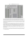
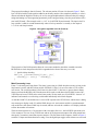
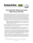
Figure 1. LabVIEW/BL2600 Virtual Instrument
In both the AN407 VI and the AN408 VI you can use switches and other controls to tell the BL2600 to set
specific analog or digital outputs. The AN408 VI adds output indicators and more I/O by using the
RN1100 expansion board. The AN408 VI reads the outputs from the BL2600, as well as from the RN1100,
to set the state of the corresponding indicators. The VI receives the outputs from shadow data, allowing for
independent setting of output data by the remote units if some autonomous control heuristics are added to
the BL2600 program.
The BL2600 program is complete enough that some developers will be able to use it without modification,
creating an application entirely in the LabVIEW development environment if local autonomy on the
BL2600 is not needed. Others will want to modify the BL2600 program to have autonomy to control processes or tests when no VI is being used, or to augment human control when using the VI. The versatility
of Dynamic C and LabVIEW make it easy to create applications with different degrees of autonomy. A
BL2600 program that runs completely autonomously but allows real-time viewing only of data in a VI is
another possibility.
Because the connection is done with simple TCP/IP socket programming, the same BL2600 program used
here could also interface with PC front ends created with such tools as Visual Basic, Delphi, or Windows
C++ development packages.
022-0102 Rev. A
2
Running the Sample Application
You can loop back I/Os on the SBC to see the VI in action, as with AN407, or connect to external input or
measurement devices. Read the BL2600 User’s Manual before using the board’s I/Os.
The BL2600
The sample program to run the SBC is BL2600_VI_02.C. The program can be found in AN408.zip
and AN408b.zip, two ZIP files that accompany this document. AN408.zip contains application files
and the installation for LabVIEW support. AN408b.zip contains only the application files.
Connecting to the Network
You must have a free, fixed IP address on your local network to run this application. Connect the BL2600
Ethernet port to a hub or switch, or connect it directly to your computer’s Ethernet port using a cross-over
cable. The PC’s IP address must be set to a fixed address different from the IP address for the BL2600.
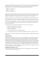
Defining the Default Configurations
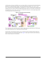
If you change nothing in the program BL2600_VI_02.C, you will be able to run the program and configure the BL2600 program using the RabbitWeb interface (i.e., the HTTP server provided in
BL2600_VI_02.C) in a web browser using the factory default address of http://10.10.6.148. (The HTTP
server and VI communications use the same IP address but different ports.)
Figure 2. Front page for configuration via browser
022-0102 Rev. A
3
To change the default IP address at compile time, the following macros near the top of the program should
be changed. These override the IP address setting in TCP_CONFIG.LIB, and are defined in separate
macros and variables as a convenience for working with them as RabbitWeb variables.
#define
#define
#define
#define
IPADDR0
IPADDR1
IPADDR2
IPADDR3
10
10
6
148
A number of other default configurations can be changed at compile time. There are too many too list here,
and they can all be changed at run-time via the more intuitive browser interfaces.If any default setting is to
be changed at compile time, it is important change at least one character in this macro definition:
#define DAK_INI_FLAG "00 BL2600 DAAK Z-World/Rabbit Semiconductor 2004"
Default configurations are stored in flash memory on program startup whenever the exact string above is
not found in the first position in the User block space in flash. The first time the program is run the configuration parameters, including DAK_INI_FLAG, are written to flash. Thereafter, they are written only if
DAK_INI_FLAG is different from the string stored at location 0 in the User block. This method is often
called “super-initialization.”
All of the following may be changed at compile-time or at run-time via the web browser:
•
•
•
•
•
BL2600 analog and digital I/O configuration
RN1100 analog and digital I/O configuration
IP address, LabVIEW port
User account IDs, passwords, and administration rights
E-mail alarms settings for inputs, e-mail alarm recipient addresses and the e-mail alarm interval
Read the code comments in the program to learn more about changing default configuration information at
compile time.
Using the RN1100
To add an RN1100 unit, connect the RN1100 power and communication cable as described in the RN1100
manual, go to the “Configure RN1100 web page” and hit the Add button. The application currently handles only one RN1100, but most of the program is structured to allow for two. Only some of the target
communication needs to be modified to handle the second unit. Modifying the VI and C program to handle
a second unit is left as an exercise for the user. The application currently sends and receives dummy data
for one RN1100 even if no RN1100 is connected. The design decision that needs to be made to handle a
second unit is whether to send dummy data for it, change the VI to handle a change in the size of the data
stream while running, or to disallow adding/removing RN1100 units while the VI is running. The first and
last choices will be the easier ones to implement.
Compile and Run BL2600_VI_02.C
Compile the program and run it as you normally would. See the “Getting Started” section of the BL2600
User’s Manual if you have not done this yet.
022-0102 Rev. A
4
The VI
The Zip file accompanying this document contains the LabVIEW file, BL2600_VI_02.VI. This file is
the VI and is modifiable with LabVIEW. The Zip file also contains an EXE version of the VI that runs
stand-alone (after installing LabVIEW support) and cannot be modified with LabVIEW. The software
needed to create EXE files from VI files is not part of the basic LabVIEW package and must be purchased
separately from National Instruments.
You can run either version of the VI, BL2600_VI_02.VI or BL2600_VI_02.EXE.
Running BL2600_VI_02.VI
Double click on the file, BL2600_VI_02.VI. You must have LabVIEW version 7.1 or later installed to
open this VI file. Now, click the Run Continuously button (Figure 3) on the LabVIEW control bar.
Figure 3.
When you start the VI, it will loop waiting for you to click the Start button. But, before pressing the Start
button, you must enter a password and user ID. The IP address and the user ID are stored in the Windows
registry and will be filled in automatically, but the password must be entered each time the program is
stopped and restarted.
“BL2600” is a default for both user ID and password programmed into the BL2600. Now, press the Start
button within the VI, and once the password is accepted, you can adjust the analog slide controls and flip
toggle switches to control output while you view input.
Running BL2600_VI_02.EXE
Before you can run the stand-alone VI, BL2600_VI_02.EXE, you must already have LabVIEW or LabVIEW support installed, or you need to run the LabVIEW client installation in the /install folder - the
installation program there is SETUP.EXE. Once you have run the installation, you can run
BL2600_VI_02.EXE by double clicking on it; then, click the Run Continuously button (Figure 3) so
that it appears black.
As described above, when you start the VI, it will loop waiting for you to press the Start button. After you
press the Start button, and once the password is accepted, you can adjust the analog slide controls and flip
toggle switches to control output.
022-0102 Rev. A
5
How It Works
This section describes details of both the LabVIEW VI and the program running on the BL2600
LabVIEW VI
The LabVIEW program is laid out as a large “flat sequence” structure. The operation is very similar to the
AN407 VI, so we will focus on the functional changes and additions here. Within LabVIEW, you can look
at the block diagram for BL2600_VI_02.VI. You can toggle between the block diagram and the front
panel by using the keyboard shortcut, Ctrl+E.
The VI discussed here uses some trickier LabVIEW techniques to convert binary data to panel indicator
data. It uses “clusters” of indicators and controls so that each indicator and control does not have to be
wired on the diagram individually, as in the AN407 VI.
Initialization
As with the AN407 VI, the first five frames of the block diagram perform fairly self-explanatory initialization and password verification. The labeling facilities of LabVIEW were heavily used to describe what
happens. The new elements are:
• Windows registry storage of the panel-entered user ID and IP address - these values are automatically put in the text entry boxes on the next run of the program.
• Some encoding is done on the password so it doesn’t get sent in clear text
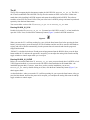
Frame 2, shown in Figure 4, defines how the stored IP address is retrieved. If there is an error reading the
registry, it is assumed that it has not been created yet and the entry is then created with default values written to it. Writing to the Windows registry is shown in the larger True block in Figure 4; the default IP
address is 10.10.6.148. If this fails, the default IP address is assigned to the appropriate variable, shown in
the small True block located within the larger one, and execution continues.
Figure 4. Getting the IP address from the registry (Frame 2)
After the Start button has been clicked, whatever was entered for the IP address on the VI panel is written
to the Windows registry. This is done in Frame 5 using the same method we just saw in the True block
from Frame 2. Writing the user ID to the registry is also done using this same method.
022-0102 Rev. A
6
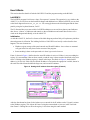
The password encoding is done in Frame 4. The relevant portion of Frame 4 is shown in Figure 5. Each
byte is XOR’ed with its index position added to an arbitrary number. (Not completely arbitrary, a value is
chosen such that the high bit will always be set for encrypted alpha numeric characters thus preventing a
string-terminating zero from appearing prematurely in the encrypted string, since the password/user ID is
sent in ASCII mode.) The rectangle with “x + 165” is a LabVIEW Expression node. The input is the For
loop variable i (which is created automatically when a For loop structure is created), so the output is
i + 165 for each loop iteration.
Figure 5. Encryption algorithm in the VI (Frame 4)
The properties of the XOR operation allow the exact same method to decode the encoded text on the
BL2600 side to check the password (which is appended to the front of the array userid):
// Quick & dirty decoding
for(j=0; j<strlen(users[i].pw); j++){
userid[j] = (165+j) ^ userid[j];
}
Main Processing Loop
Frame 7 is the main processing frame. The frame’s processing is a While loop that executes as long as the
Stop button is not hit, and the boolean variable STOPALL is false. It is set to true when a TCP or other
error occurs. The overall operation is like Frame 6 in the AN407 VI, but here we process data in binary
format sent from the BL2600; ASCII mode must still be used to send data to the BL2600, because LabVIEW Express has no TCP/IP socket write binary mode. We also make use of LabVIEW’s “clusters” of
indicators and controls to avoid wiring each channel individually in the block diagram.
As with the AN407 VI, the default case is a non-ACK’ed password or TCP/IP error, which causes a dialog
error message to display on the VI, and the While loop to exit. An iteration variable is created automatically at the lower left when a While loop is created, and here we hook the variable to a VI display indicator
to show the number of iterations.
The next nested structure is a Case structure with a true and a false case - the LabVIEW equivalent of an
if-else construct. The case for no TCP/IP error and an ACK’ed password (output of the string match function equals 5) contains a nested flat sequence structure. The first frame in the sequence, shown in Figure 6,
reads the VI inputs and forms them into a string. First, the digital input toggle switch clusters are converted
022-0102 Rev. A
7
to boolean arrays to integers and finally to two text strings which are concatenated to form the initial string
input for the “Format into string” function. The format string function with the “%6.3f %6.3f %6.3f
%6.3f” format specifier will look familiar to C programmers. It is used to format the analog output control
floating point values. Finally, the RN1100 digital output toggle switches are converted to an ASCII integer
and appended to the output string. Again, the use of clusters here makes for a much simpler diagram than
if each element had to be wired one at a time.
Figure 6. Forming the output data string
The second frame in the nested flat sequence sends the output string to the BL2600 with a TCP/IP socket
write, and the third frame receives a data packet from the BL2600.
The third frame in the nested flat sequence receives a binary data string containing both input data and
shadow output data from the BL2600 and RN1100. Figure 7 shows a part of the conversion from binary
data to VI panel output in the fourth frame.
022-0102 Rev. A
8
Figure 7. Converting binary data to VI panel output
The conversion for digital values requires extracting the correct number of bytes from the correct offset in
the data packet, reversing the byte order if it is a multi-byte value, converting to an unsigned integer of the
right size, then to a boolean array which is fed to a cluster of panel indicators. Note that a numeric constant
is used to define the type and size of the output of the Type Cast function. The value of the constant is
meaningless, the constant’s data type and size are set in the properties dialog of the constant. For analog
values, For-loop structures are used to extract one 4-byte floating point value at a time from the data
packet and insert it into an array of floating point values which are fed to a of cluster of VI panel indicators.
022-0102 Rev. A
9
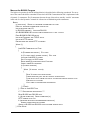
More on the BL2600 Program
The high-level operation for the BL2600 application is described in the following pseudocode. The structure of the actual code differs somewhat because the LabVIEW Communication task is implemented with
a Dynamic C costatement. The If statements shown at the top of the task are actually “waitfor” statements
in the code. See the Dynamic C manual for a discussion of multitasking with costatements.
BEGIN:
IF (FIRST RUN) WRITE ALL PROGRAM PARAMETERS TO FLASH
READ ALL PROGRAM PARAMETERS FROM FLASH
INITIALIZE BOARD AND I/O
IF (RN1100 PRESENT) INITIALIZE RN1100
SET BL2600&RN1100 OUTPUTS AND SHADOW DATA TO INIT. VALUES
READ BL2600 & RN1100 INPUTS
INITIALIZE ETHERNET AND TCP/IP STACK
INITIALIZE HTTP SERVER
DEFINE USER AND ADMIN HTTP ACCESSES
WHILE (1)
[
LABVIEW COMMUNICATION TASK
[
IF (ETHERNET NOT READY) EXIT TASK
IF (VI CLIENT HASN'T OPENED SOCKET) EXIT TASK
INITIALIZE LABVIEW VI SOCKET
SET VI SOCKET TO ASCII MODE
READ USERID & PASSWORD FROM VI SOCKET
VERIFY USERID & PASSWORD
IF (ACCESS GRANTED)
[
WHILE (VI SOCKET ACTIVE)
[
READ VI PANEL DATA FROM SOCKET
PARSE RECEIVED DATA AND SET OUTPUT SHADOW DATA
FORM DATA FOR VI FROM LAST INPUT VALUES AND SHADOW OUTPUT DATA
WRITE DATA TO SOCKET
YIELD TIME TO BACKGROUND PROCESSING
]
] // END IF
] // END OF LABVIEW TASK
//**** BACKGROUND PROCESSING ****
READ BL2600 AND RN1100 DATA
IF (ALARM CONDITION) SEND ALARM EMAIL(S)
HTTP SERVER TICK CALL
IF (MESSAGE RECEIVED FROM BROWSER INTERFACE)
HANDLE CONFIGURATION CHANGES
WRITE TO BL2600 AND RN1100 OUTPUTS FROM SHADOW DATA
] // END WHILE
022-0102 Rev. A
10
E-Mail Alarms
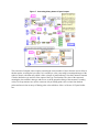
From the page shown in Figure 2, click on the link titled “Configure E-Mail Alarms” to go to the page
shown in Figure 8. As you can see, it is easy to configure an e-mail alarm for any of the I/O channels. The
BL2600 will send an e-mail to all of the addresses listed whenever an alarm condition is true. To repeatedly send e-mails while the alarm condition remains true, type a value other than 0 in the textbox labeled
“Interval.” The unit of measure is 15 minutes, so a value of 4 causes an e-mail to be sent every 60 minutes.
Figure 8.
022-0102 Rev. A
11
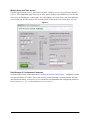
Multiple Users and Their Access
From the page shown in Figure 2, click on the link titled “Configure Access” to go to the page shown in
Figure 9. This configuration page allows you to make runtime changes to the IP addresses, as well as the
list of users. By checking the “Admin rights” box when adding a user to the list you can allow additional
access to that user. This has some security concerns which are discussed in the section titled, “Security.”
Figure 9.
Flash Storage of Configuration Parameters
As mentioned previously in the section titled, “Defining the Default Configurations,” configuration parameters are stored in the User block. This is an area on the primary flash that is accessed with the API functions found in the library IDBLOCK.LIB. To examine the code that handles the configuration parameters,
look in BL2600_VI_02.C at the function InitializeAll().
022-0102 Rev. A
12
Security
Configuration pages in the web interface are password protected. Up to 16 users may be defined with usernames and passwords that are used for both the web configuration and the VI front panel access. Only
users with administration rights may change configurations via the browser interface. The default administrator username and password are both admin1. Two additional default username/passwords are provided
without administration rights, BL2600/BL2600 and user01/user01. When you change user accesses at runtime, you will not be able to use the same word for username and password. Other rules and instructions
for changing user information and other parameters are shown in the configuration web pages. Whenever
security might be an issue, it is advisable to change all the user passwords at compile time or at run-time
before deploying.
The password protection for the configuration web pages uses digest authentication. It could be modified
to use SSL with the purchase of the Dynamic C SSL module. Transmission security for access to the
BL2600 through the VI panel is achieved by a quick-and-dirty encoding of the password that would be no
challenge to a serious hacker. If more security is desired for TCP/IP within LabVIEW, developers will
have to explore what is available from National Instruments or third parties. LabVIEW Express 7.1 has
nothing available for enhanced TCP/IP security short of implementing security protocols by hand.
If high security is important, disallow users with admin rights use of the VI interface so that admin passwords are not habitually sent with weak encoding from the VI. The following commented-out line is
included in the source code to disallow users with admin rights from using the VI:
// Use this if test instead to prevent administrator from
//
using the LabVIEW VI
// if(!strcmp(userid, inbuffer) && users[i].group != admin)
Allowing only viewing of data in the VI so that dedicated hackers could not change outputs on the BL2600
remotely is another possible security measure.
Distributed VIs can have the block diagram password protected for no write access without a correct password, no read or write access without a password, or no password protection at all. This is done on the
LabVIEW file menu.
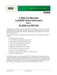
More Information
• Z-World: www.zworld.com
• Rabbit Semiconductor: www.rabbitsemiconductor.com
• National Instruments: www.ni.com
Z-World, Inc.
Rabbit Semiconductor
2900 Spafford Street
Davis, California 95616-6800
USA
2932 Spafford Street
Davis, California 95616-6800
USA
Telephone: (530) 757-3737
Fax: (530) 757-3792
Telephone: (530) 757-8400
Fax: (530) 757-8402
www.zworld.com
www.rabbitsemiconductor.com
022-0102 Rev. A
13