1
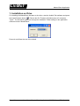
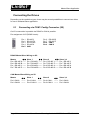
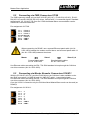
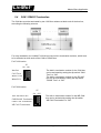
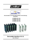
Documentation of the Master/Slave Application for the following Drives: - Series E1100 Series E1200 Master/Slave Application User Manual LinMot Master/Slave Application © 2012 NTI AG This work is protected by copyright. Under the copyright laws, this publication may not be reproduced or transmitted in any form, electronic or mechanical, including photocopying, recording, microfilm, storing in an information retrieval system, not even for didactical use, or translating, in whole or in part, without the prior written consent of NTI AG. LinMot® is a registered trademark of NTI AG. Note The information in this documentation reflects the stage of development at the time of press and is therefore without obligation. NTI AG reserves itself the right to make changes at any time and without notice to reflect further technical advance or product improvement. Document version 3.17 / May 2012 Page 2/11 User Manual Master/Slave Application / 15/05/2012 NTI AG / LinMot Master/Slave Application LinMot Table of Content 1. INSTALLATION ON DRIVE................................................................................................ 4 2. SYSTEM OVERVIEW......................................................................................................... 5 CONNECTING THE DRIVES................................................................................................. 6 2.1 CONNECTING VIA COM / CONFIG CONNECTOR (X5)................................................................... 6 2.2 CONNECTING VIA CMD CONNECTORS X7/X8............................................................................ 7 2.3 CONNECTING VIA MASTER ENCODER CONNECTORS X10/X11....................................................... 7 2.4 CAN / RS485 TERMINATION................................................................................................ 8 3. USING THE MASTER/SLAVE SW..................................................................................... 9 4. MASTER SLAVE PARAMETERS.................................................................................... 10 5. RECONNECTION AFTER QUICK STOP / ERROR......................................................... 10 6. CONTACT ADDRESSES................................................................................................. 11 NTI AG / LinMot User Manual Master/Slave Application / 15/05/2012 Page 3/11 LinMot Master/Slave Application 1. Installation on Drive For installing the MasterSlave firmware on the drive, start the LinMot-Talk software and press the install firmware button . Choose the file “Firmware_Buildxxxxxxxx.sct” and press “Open”. The wizard will guide you through the installation. When asking for the application software choose “MasterSlave” Press ok and follow the rest of the wizard. Page 4/11 User Manual Master/Slave Application / 15/05/2012 NTI AG / LinMot Master/Slave Application LinMot 2. System Overview The Master/Slave application SW is an additional firmware part for the following features: • • Current master motor with a maximum of three current slave motors to increase the force. The current delay in all slaves is about 300us Gantry master motor with a maximum of three gantry slave motors, which have the same position setpoints. The setpoint delay for all slaves is about 300us. If a synchronous communication mode is used, or if the cycle time of the used fieldbus is short enough, it is recommended to realize the master gantry mode within the PLC, because of higher flexibility and easier use (2 normal axis instead of 1 master axis with attached slave information; especially in the error handling case). The Master/Slave application SW supports the Master/Slave communication link either over the CAN bus (X7/X8, X10/X11 or X5) or RS485 (X7/X8 or X5). If CAN bus interfaces (like CANopen or DeviceNet) are to be used for communication with the drive, the RS485 based link has to be used for the Master/Slave application. For all other interfaces the CAN bus link mode should be used, because the RS232 maintenance link on X5 Connector is still available. The performance of both links CAN or RS485 is the same. If the Master/Slave is linked over RS485, it is no longer possible to configure or to debug the drive over RS232 (X5). LinMot-Talk configuration software supports an USB to CAN converter (Part No. 0150-3134 ) for this purpose. On the E1200 drive series only the Current Master/Slave functionality over ME CAN X10/X11 is supported. Although the Master/Slave application is available on E1100 and E1200 drive series, drives from different series cannot be linked together. NTI AG / LinMot User Manual Master/Slave Application / 15/05/2012 Page 5/11 LinMot Master/Slave Application Connecting the Drives Depending on the used drive types, there may be several possibilities to connect two drives for use in a Master/Slave application: 2.1 Connecting via COM / Config Connector (X5) On X5 a connection is possible via RS485 or CAN is possible. Pin assignment of X5 (DSUB 9 male): Pin 1 Pin 2 Pin 3 Pin 4 Pin 5 RS-485 Y RS-232 TX RS-232 RX RS-485 A GND Pin 6 Pin 7 Pin 8 Pin 9 RS-485 B RS-485 Z CAN L CAN H RS485 Master/Slave Wiring on X5: Master Slave 1 Pin 4 RS-485 A -----Pin 6 RS-485 B -----Pin 1 RS-485 Y -----Pin 7 RS-485 Z ------ Slave 2 Pin 1 RS-485 Y -----Pin 7 RS-485 Z -----Pin 4 RS-485 A -----Pin 6 RS-485 B ------ Slave 3,4 Pin 1 RS-485 Y -----Pin 7 RS-485 Z -----Pin 4 RS-485 A -----Pin 6 RS-485 B ------ Pin 1 RS-485 Y Pin 7 RS-485 Z Pin 4 RS-485 A Pin 6 RS-485 B Slave 2 Slave 3,4 CAN Master/Slave Wiring on X5: Master Slave 1 Pin 8 CAN L ------- Pin 8 CAN L ------- Pin 8 CAN L ------- Pin 8 CAN L Pin 9 CAN H ------- Pin 9 CAN H ------- Pin 9 CAN H ------- Pin 9 CAN H Page 6/11 User Manual Master/Slave Application / 15/05/2012 NTI AG / LinMot LinMot Master/Slave Application 2.2 Connecting via CMD Connectors X7/X8 The CMD connector exists only on the E1130-DP(-HC/-XC), E1100-CO(-HC/-XC), E1100DN(-HC/-XC) and E1100-RS(-HC/-XC) drives, 2xRJ45 with 1:1 connected signals. Standard twisted pairs: 1/2, 3/6, 4/5, 7/8. Over the X7/X8 the Master/Slave communication can be realized for CAN and RS485 link. Pin assignment of X7/X8: Pin 1 Pin 2 Pin 3 Pin 4/5 Pin 6 Pin 7 Pin 8 RS485 A RS485 B RS485 Y Ground RS485 Z CAN H CAN L When connecting via RS485, use a crossed Ethernet patch cable (Art. Nr. 0150-1853) between the master and first slave, and a normal patch cable 1:1 (Art. Nr. 0150-1852) between the slaves. Master Crossed patch cable Art. Nr. 0150-1853 Slave 1 Slave 2,3,4 Standard patch cables Art. Nr. 0150-1852 Use Ethernet cables according the EIA / TIA 568A standard to loop through the CAN bus over this connector (Art. Nr. 0150-1852). 2.3 Connecting via Master Encoder Connectors X10/X11 With the E1100-GP(-HC/-XC) and the E1200 drives, the CAN bus is also available on the two RJ45 connectors X10 (ME IN) and X11 (ME OUT) with 1:1 connected signals. Use Ethernet cables according the EIA / TIA 568A standard to loop through the CAN bus over this connector (Art. Nr. 0150-1852). Over the X10/X11 connection only the CAN bus linked Master/Slave mode can be used (no RS485)! Pin assignment of X10/X11: Pin 1 Pin 2 Pin 3 Pin 4 PIN 5 Pin 6 Pin 7 Pin 8 NTI AG / LinMot A /A B Z /Z /B CAN H CAN L User Manual Master/Slave Application / 15/05/2012 Page 7/11 LinMot 2.4 Master/Slave Application CAN / RS485 Termination The CAN bus must be terminated by two 120 Ohm resistors at both ends of the bus line, according the following scheme: For easy installation, the LinMot E1100 drives have built in termination resistors, which have to be activated on both ends of the CAN or RS485 bus. For E1100 series: S3 On - Off Interface CAN Term RS485 Term RS485/232 The built in termination resistor for the CAN bus can be activated by setting the dip switch “CAN Term” to “ON”. The built in termination resistor for the RS 485 bus can be activated by setting the dip switch “RS485 Term” to “ON”. 4 3 2 1 For E1200 series: S5 On - Off X4.4 Pull Down 4k7 CMD RS485 Termination CMD CAN Termination ME CAN Termination Page 8/11 4 3 2 1 The built in termination resistor for the ME CAN bus can be activated by setting the dip switch “ME CAN Termination” to “ON”. User Manual Master/Slave Application / 15/05/2012 NTI AG / LinMot Master/Slave Application LinMot 3. Using the Master/Slave SW To install the Master/Slave application software start the LinMot-Talk software (if already started and logged in then logout), click on the Install Firmware button and select the installation script: Firmware_VxSx_Buildxxxxxxxx.sct Then choose the application “MasterSlave” The same Master/Slave application SW has to be loaded to the master as well as the slave drive(s). Select the required serial link CAN or RS 485 (UPID 3EF7h). After the Master/Slave application SW has been installed, log in all slave drives and select the correct Master/Slave mode (UPID 30D4h). The rest can be left as configured by default. After power up the master drive tries to connect to its slave drives, when it succeeds to connect to the slave(s), the application Warn Flag bit 15 vanishes and the connection state (UPID 3A98h or 3A99h) changes to 1, which means ‘Data Exchange’. The state of the slave drive can be monitored over the variables “Slave 0..2 State Var” (UPID 3B70h, UPID 3B72h, UPID 3B74h,). As the slave drive is in a streaming mode (current or position), in state 8 ‘Operation Enabled’ bit 5 ‘Motion Active’ is normally set and bit 6 ‘In Target Position’ is cleared in the Slave State Var. Bit 8 ‘Homed ‘ indicates whether the slave drive has been correctly homed or not. The slave state machine is controlled from the master, so if connecting a serial fieldbus link to the slave drive for monitoring reasons, take care not to write to the slave’s control word. So, with Profibus DP interface do not configure the control status module for any slave, the status word can be watched by using a monitoring channel UPID 1D51h. NOTE: Both master and slave(s) have to be configured by using the Motor Wizard. NTI AG / LinMot User Manual Master/Slave Application / 15/05/2012 Page 9/11 LinMot Master/Slave Application 4. Master Slave Parameters The Master/Slave drives have an additional parameter tree branch, which can be configured with the distributed LinMot-Talk software. With these parameters, the Master/Slave behaviour is set up. The software LinMot-Talk can be downloaded from http://www.linmot.com under the section download, software & manuals. Serial Link Selection selects the communication link between master and slave. Master Slave Appl\ Serial Link Selection CAN [0] Master/Slave communication over CAN bus 1Mbaud. RS485[1] Master/Slave communication over RS485. Master Slave Mode defines the master/slave behaviour of the drive. Master Slave Appl\ Master Slave Mode Disable [0] The drive runs without Master Slave behaviour. Current Master[1] The drive acts as current master Current Slave [2] The drive acts as current slave Gantry Master [3] The drive acts as gantry master Gantry Slave [4] The drive acts as gantry slave Master Config In this section the further master configuration is done. Master MACID The ID of the master drive, default = 1. Do not change this parameter. Number of Slaves The number of slaves, a maximum of three slaves is possible. Slave Config In this section the further slave configuration is done. Slave MACID The ID for all slave drives, default = 2. Do not change this parameter. Slave Number Every used slave has to be defined with a unique number (0-2, allocation upwards) Direction Choose ‘Normal’ if the slave motor has the same orientation as the master motor, otherwise choose ‘Inverted’. CAN Baud Rate In this section the CAN baud rate is configured. Baud Rate Parameter Definition The CAN baud rate is fixed to 1M baud by this parameter. 5. Reconnection after Quick Stop / Error After a quick stop or an error it is important to synchronize the position of the master and the slave axis. In this case use the state ”Go to Initial Position”(see “State Machine” in the document Usermanual_MotionCtrSW). Page 10/11 User Manual Master/Slave Application / 15/05/2012 NTI AG / LinMot LinMot Master/Slave Application 6. Contact Addresses ----------------------------------------------------------------------------------------------------------------------------SWITZERLAND NTI AG Haerdlistr. 15 CH-8957 Spreitenbach Sales and Administration: +41-(0)56-419 91 91 [email protected] Tech. Support: +41-(0)56-544 71 00 [email protected] Tech. Support (Skype) : skype:support.linmot Fax: Web: +41-(0)56-419 91 92 http://www.linmot.com/ ----------------------------------------------------------------------------------------------------------------------------USA LinMot, Inc. 5750 Townline Road Elkhorn, WI 53121 Sales and Administration: 877-546-3270 262-743-2555 Tech. Support: 877-804-0718 262-743-1284 Fax: 800-463-8708 262-723-6688 E-Mail: Web: [email protected] http://www.linmot-usa.com/ ----------------------------------------------------------------------------------------------------------------------------Please visit http://www.linmot.com/ to find the distribution near you. Smart solutions are… NTI AG / LinMot User Manual Master/Slave Application / 15/05/2012 Page 11/11