1
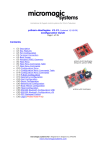
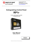
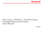
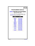
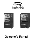
FASTCORP, LLC
EVOLUTION FS-01
SETUP AND USER MANUAL
Firmware Level V1.18A
-1–
Revision A
10/22/09
Thank you for purchasing a FASTCORP EVOLUTION frozen
merchandiser. This guide will cover the basics of setting up your
machine for the first time. Please observe the safety precautions at
the beginning of this manual.
This machine represents over 2 years of product development and
incorporates many technological advances offering you years of
service without obsolescence.
It is our sincere philosophy that we are partners with our customers
and must grow together. With that in mind, we welcome all comments
and suggestions either through your sales representative, our
customer service department or whomever you have contact with
from FASTCORP.
Refer to this manual as you start with the EVOLUTION in frozen
merchandisers from FASTCORP.
Thank you,
The FASTCORP Team
Firmware Level V1.18A
-2–
Revision A
10/22/09
PRECAUTIONARY NOTES
!!DANGER!! THE VENDER MUST BE PROPERLY LOCATED AND LEVELED.
IF THE MACHINE WILL BE SUBJECT TO USER MISUSE OR VANDALISM, IT
IS RECOMMENDED THAT THE VENDER BE SECURED TO THE FLOOR OR
WALL TO MINIMIZE RISK OF INJURY OR DEATH FROM TIPPING.
CALL THE FASTCORP TECHNICAL SERVICE DEPARTMENT AT
(888) 441-3278 FOR ASSISTANCE.
Adjust the front leveling legs, to level the cabinet front-to-rear then adjust the
front and rear legs an equal number of turns to level left to right. A carpenter’s
level placed on top of the machine (front to back & left to right) will help verify that
the machine is level. Leveling legs are adjusted using a wrench or socket 1-3/8
inches in size. Lowering the legs will raise the machine approximately 1/4” per 4
turns. If the machine is to be used next to another vender, check the top and side
for proper alignment. Minimum leg extensions should be used in leveling and
alignment to attain greater stability. Make sure that all the leveling legs are in
contact with the floor. If you cannot level the vender, select another location. Do
not place any objects under the machine. Leveling is extremely important to
ensure proper vender operation. Do not program or operate the machine before
the leveling process I complete. If preprogramming selections in a warehouse
prior to placement, the machine must be leveled again at the new location and all
the program selections checked for proper robot-bin alignment.
POSITIONING THE MACHINE
Do not block the rear of the vender. Keep the vender 4 inches (10 cm) from the
wall to ensure adequate ventilation airflow. At the rear of the vender, make sure
nothing obstructs the air vents at the top and the fan louvers at the bottom of the
cabinet.
Firmware Level V1.18A
-3–
Revision A
10/22/09
FAMILIARIZING YOURSELF TO THE NEW ROBOT
Firmware Level V1.18A
-4–
Revision A
10/22/09
ELECTRIC POWER REQUIREMENTS
The cabinet serial plate indicates the proper Voltage and Amperage required for
the vender (domestically this requirement is 115 Volts, 60 Hertz). The vender
must be plugged into its own properly rated single phase, grounded, alternating
current outlet with its own circuit protection (fuse/circuit breaker).
DO NOT USE AN EXTENSION CORD OR POWER STRIP TO SUPPLY
POWER TO THE MACHINE.
GROUND THE VENDER
The vender is equipped with a three wire power supply cord and MUST be
plugged into a properly grounded outlet. If the outlet will not accept the power
cord plug, contact an electrician to install a proper AC outlet.
DO NOT REMOVE THE GROUND PIN OR IN ANY WAY BYPASS, MODIFY,
DEFEAT, OR DESTROY THE GROUNDING SYSTEM OF THE VENDER.
FAILURE TO COMPLY WITH THESE INSTRUCTIONS MAY SUBJECT THE
USER TO THE RISK OF INJURY OR ELECTRICAL SHOCK WHICH CAN BE
SERIOUS OR FATAL.
Firmware Level V1.18A
-5–
Revision A
10/22/09
UNPACKING INSTRUCTIONS
!! ATTENTION !!
ALL SHIPPING BRACKETS MUST BE REMOVED BEFORE
APPLYING POWER TO THE MACHINE. FAILURE TO DO
THIS MAY RESULT IN PERMANENT DAMAGE TO THE
ROBOT OR ELECTRONICS
Tools required: 5/16” wrench or nutdriver, 7/16” wrench, cutting pliers
There are two (2) brackets that need to be removed. The first is
in the upper-right of the cabinet and it secures the robot to the wall.
Using a 5/16” wrench, remove the two (2) screws on the front clamp.
Loosen the two (2) screws on the rear clamp. The robot arm may now
be moved out of the bracket. Using a 7/16” wrench remove the two
(2) nuts that attach the bracket to the ceiling studs. Remove the
bracket and store all parts for future use when shipping or moving the
machine.
Next we remove the freezer lid shipping bracket. This is located
on the right side of the cabinet midway back on the freezer lid.Using a
5/16” wrench, remove the two (2) screws that attach the bracket to
the lid lift bracket. Remove the bracket and store all parts for future
use when shipping or moving the machine.
The final item is the installation of the vacuum pump. In the
product chute you will find the vacuum pump. Unwrap from the
packing materials. Locate the lift cable connector in the front of the
robot arm. It is secured with a red cable tie. Cut this cable tie and
discard. Take the cable connector and insert it into the mating
housing on the vacuum pump. You may need to rotate it slightly so
the alignment spline engages. Now tighten the locking ring. NOTE:
DO NOT USE TOOLS – FINGER TIGHTEN ONLY
You can now safely plug the machine in. Turn on the main power
switch that is located just behind the freezer. This supplies power to
the freezer and lights.
Next, turn on the controls power switch located on the end of the
power supply at the bottom of the door under the product chute.
Firmware Level V1.18A
-6–
Revision A
10/22/09
FREEZER MAINTENANCE
Viewing freezer temperature: while in Vend Mode (indicated by the
scrolling marquee on the digital display), press the “*” key on the
Customer Keypad. The current temperature will be displayed on the
digital display.
Several hours after powering up the machine; the freezer
temperature should drop to about –15ºF/-26ºC.
The standard chest freezer inside the EVOLUTION FS-01 does not
self-defrost automatically. The freezer chest requires maintenance
when ice begins to affect the vend cycle, product loading, or the
closing of the freezer door. The refrigeration system does not require
any maintenance. Depending on the location’s moisture level (relative
humidity) and frequency of operation, ice deposits will occur primarily
around the top three to four inches of the freezer. It is not necessary
to defrost the freezer every time there is ice build up.
Ice can be chipped away as long as it does not make its way down
along the walls or underneath the bins. Excessive ice build-up may
require bin removal. The freezer does not have to be unplugged to
perform this process.
FASTCORP recommends keeping a plastic ice scraper (provided
with the machine), and a 9” by 11” piece of cardboard or plastic inside
the machine. Place the plastic under the area to be scraped to
prevent the ice from falling into the bins. This entire process should
only take a few minutes.
PRODUCT DISPLAY SYSTEM
1. Determine what products will be vended and locate the
corresponding display card provided by the manufacturer.
2. Affix the correct price label to the front of each selections card
3. Open the main door.
4. Every card slot on the product display sheet has holder tabs.
Secure each product card by inserting the card into the card holder
tabs (with product cards facing forward).
Firmware Level V1.18A
-7–
Revision A
10/22/09
BIN SETUP/ PLAN-O-GRAM
Fig. 8 Plan-O-Gram (Aerial View)
Note: When programming, it is important to program the bin selections located on
the left as short bins; the rest are tall bins. If short bins are programmed as tall
bins, the robot will make contact with the bottom of the bins and attempt to pull
them out, resulting in possible machine failure (out-of-order). If tall bins are
programmed as short bins, the machine will only vend product based on the
height of a short bin. The robot will leave product at the bottom of the tall bin and
flag it Out-Of-Product.
PRODUCT MUST ALWAYS BE LEVEL IN BINS (ALTERNATE PRODUCT
DIRECTION WHEN LOADING CONE BINS)
Firmware Level V1.18A
-8–
Revision A
10/22/09
PROGRAMMING
The following instructions reference V1.18A operational firmware.
INTRODUCTION
The machine comes from the factory without any preset selection numbers or bin
locations in memory (except Cafe2Go machines with standard plan-o-gram). All
information is entered during initial setup and programming. Programming is
menu driven. Simply scroll through the menus until the desired function is
reached. Once inside a menu function, the computer will prompt the user to enter
the required information.
Programming Menus are accessed in Service Mode. The machine enters Service
Mode every time the cabinet door is opened.
NOTE: THE VAC BUTTON ON THE SERVICE KEYPAD MUST BE PRESSED
TO DISABLE THE SECURITY-LOCKING FEATURE (DISPLAY- “KEYPAD IS
LOCKED”), ENABLING USE OF THE CUSTOMER KEYPAD.
Once enabled, pressing the “*=Next” key on the Customer Keypad will list all the
menu items on the digital display.
Note: if the machine is programmed in one location and transported to another,
(for example in your warehouse) it is important to re-level the machine at the new
location and perform test vends on each selection. Reprogram/edit bins as
needed.
MENU ITEMS: (SHADED ITEMS NOT AVAILABLE AS OF THIS RELEASE)
1) CHANGE PRICE: Allows the prices to be changed.
2) SALES METERS: Allows sales data to be viewed.
3) EDIT SELECTION: Allows existing selections bin positions to be edited.
4) CREATE SELECTION: Allows a selection to be created.
5) DELETE SELECTION: Allows a selection to be deleted.
6) SELECTION NUMBERS: Allows programmed selection numbers to be
viewed. (Use to check for erroneous selections)
7) SET DATE & TIME: Allows date and time to be set or viewed.
8) AUTO VENDS: Used internally to cycle vend units under test.
9) SERVICE PHONE #: Allows service phone number to be set. The number is
displayed when the machine is out-of-order. (Do not use FASTCORP’S #)
10) SALES PIN CODE: Allows PIN code to be set and viewed for machine
auditing. Audit data can be viewed without opening the door.
11) VEND BLOCK: Allows the machine to be disabled for predetermined periods
of time.
Firmware Level V1.18A
-9–
Revision A
10/22/09
12) VEND BLOCK PIN CODE: Allows a PIN code to be set for control of the
vend block function without opening the door.
13) HEALTH TIMER: Allows a 1-time grace period of 1,2,3 or 4 hours where the
health control is suspended; choice of displaying the freezer temperature in
either Fahrenheit or Centigrade and the choice of health sensor mode to operate
in: NAMA Ice Cream, Test, Super Cold and Frozen Food.
14) PROGRAM VERSION: Displays version of firmware installed on VMC.
15) DISPLAY LANGUAGE: Allows the programmer to choose the language
displayed on the screen.
16) LINE MODE: Allows the machine to detect a customer line and shortens the
vend time.
17) MACHINE SERIAL NUMBER: Allows the programmer to enter up to a 10digit serial number for machine identification during DEXing.
18) FILL / DISPENSE: Allows viewing of coin counts in the tubes of the mech.
19) TOKENS & COUPONS: Allows coupons and tokens to be recognized as free
or valued vends and records sales in appropriate DEX fields.
20) FIELD TEST: Allows the machine to run in a diagnostic mode to allow for
quick troubleshooting.
21) U/PDOWN TRAVEL LIMIT: This feature allows the customer to adjust how
deep the Picker Tip will descend into both tall and short bins. NOTE: Increasing
the number will cause the vacuum pump to travel further into the bin. Changing
this value by 5 represents a change in travel of 1 inch.
22) VERIFY ALL BINS: Automatically moves robot over each bin position. Allows
user to verify and edit bin programming.
23) MDB SETTINGS: Force vend, Multi vend, etc.
24) SOFT DROP: Allows enabling and setting the “Soft-Drop” feature that lowers
the product before it releases it into the product chute.
Firmware Level V1.18A
- 10 –
Revision A
10/22/09
GETTING STARTED
CALIBRATING THE ROBOT ARM
If you get the message “MACHINE NOT SET UP”, you will need to calibrate the
robot arm. This typically only appears when the robot arm is first calibrated to the
cabinet. If you do not get this message, proceed to the programming part of the
setup.
1) Scroll to menu “4) CREATE SELECTION”
2: Press the “#” key to create a selection. You will be prompted to “SET ARM AT
LEFT WALL”. Position the arm shown in figure 9A. Press the “#” key to accept.
Display will show “SELECTION STORED”
3) Now you will be prompted to “SET ARM AT DELIVERY”. Position the arm as
shown in figure 9B. Press the “#” key to accept. Display will show “SELECTION
STORED”
4) Display should return to “4) CREATE SELECTION”
5) You may now program your selections as described in the “PROGRAMMING
YOUR MACHINE” section on page 14.
Figure 9A
Firmware Level V1.18A
Figure 9B
- 11 –
Revision A
10/22/09
NOTE: SOME MENU ITEMS ARE NOT FULLY OPERATIONAL AS OF THIS
RELEASE. THESE ITEMS WILL BE SHOWN IN LIGHT GRAY OR NOT AT
ALL.
1) CHANGE PRICE - Changing the price of programmed selections.
Display
1) CHANGE PRICE
* = Next D = Back # = Yes
Enter Select #:_ _
# = Exit
A1 Price: $1.00
*=Exit
#=Accept
A1 Price: $1.50
*=Exit
#=Accept
Programming Instructions
Press the #=Yes key.
Enter the selection number.
Type over the price.
Press the #=Yes key to enter the price change.
2A) SALES METERS – Both TOTAL and RESETTABLE sales meters are
accessed through this menu. The RESETTABLE offers individual and total sales
data by selection, which can be cleared/reset.
Display
2) SALES METERS
* = Next
D = Back
# = Yes
Total Vends *=Next
975
Total Value = *=Next
$1575.30
Selection
A1
25
$40.00
Selection
A2
15
$22.50
Reset.
Vends
*=Next
40
Reset.
Values
*=Next
$72.50
Reset.
Card
*=Next
$10.00
Clear All
OK?
*=No
#=Yes
Resettables Cleared
Firmware Level V1.18A
Programming Instructions
Press the #=Yes key.
This displays the Total unit count.
This displays the Value of the Total
sales.
Now you are displaying sales data by
each selection. Press “*” to proceed to
the next selection.
Press “*” to proceed to the next menu.
Press “*” to proceed to the next menu.
Press “*” to proceed to the next menu.
Press “#” to clear the resettable
meters.
You will hear a long beep and the
resettables will be cleared.
- 12 –
Revision A
10/22/09
3) EDIT SELECTION – Allows you to change the price, edit bin location or add
additional chained bins.
Display
3) EDIT SELECTION
* = Next
D = Back
# = Yes
ENTER SELECT #_ _
# = Exit
A1 Price:
$1.00
*=Exit
#=Accept
A1
Move The Robot
*=Cancel
#=Accept
Programming Instructions
Press the #=Yes key. The robot will go
to the delivery point and the freezer lid
will open.
Enter selection number to be edited.
Type over the price and press the “#”
key.
Adjust the position of the robot over the
bin. Press “#” key to save the bin
location.
Bin Height:
Tall
*=Change
#=Accept
More Bins?
a) Press the #=Yes key to add chained
bins.
*=No
#=Yes
NOTE: AS OF THIS REVISION ALL BIN CHAINING MUST ME DONE IN THE
“4) CREATE SELECTION” MENU AT THE TIME THE SELECTION IS
CREATED. THIS FEATURE WILL BE ENABLED SOON. IF AN ADDITIONAL BIN
NEEDS TO BE ADDED TO A SELECTION, DELETE THAT SELECTION AND
CREATE IT NEW WITH THE ADDITIONAL BINS.
Firmware Level V1.18A
- 13 –
Revision A
10/22/09
4) CREATE SELECTION - Create new selections, with the ability to chain
multiple bins to a single selection.
NOTE: WHEN POSITIONING THE ROBOT TO A PARTICULAR BIN, THE
ELBOW SHOULD POINT TO THE OPPOSITE SIDE OF THE FREEZER FROM
WHICH THE SELECTED BIN IS. EXAMPLE- IF THE BIN IS LOCATED ON THE
LEFT SIDE OF THE FREEZER THE ROBOT ELBOW SHOULD POINT TO THE
RIGHT SIDE AND VICE VERSA. BINS NEAR THE CENTER OF THE FREEZER
MAY BE PROGRAMMED WITH THE ELBOW PINTING TO EITHER SIDE.
Display
4) CREATE SELECTION
* = Next
D = Back
# = Yes
ENTER SELECT #_ _
# = Exit
A1 Price
$1.00
*=Exit
#=Accept
A1
*=Cancel
Move The Robot
#=Accept
Bin Height:
Tall
*=Change
#=Accept
More Bins?
*=No
#=Yes
Firmware Level V1.18A
Programming Instructions
Press the #=Yes key.
Enter selection number to be edited.
Type in the price and press the “#” key.
The robot will go to the delivery point
and the freezer lid will open.
Move the robot over the bin. This can
be done manually or using the service
keypad. Press “#” key to save the bin
location.
Select Tall or Short using the “*” key.
Press “#” to save this setting.
a) Press the #=Yes key to add chained
bins, “*” when complete.
- 14 –
Revision A
10/22/09
5) DELETE SELECTION – Delete a/all the selection(s).
Display
5) DELETE SELECTION
*=Next
D = Back
#=Yes
Delete Selection #: A1 (All selections)
*=Ex
D=Del
#=Next
OK?
Delete Selection # A5
*=No
#=Yes
Programming Instructions
Press the #Yes key to scroll to a
selection to delete.
Press the #=Next key to scroll through
the selection numbers. Press the
D=Delete key to delete the desired
selection.
Press the #=Yes key to delete selection
6) SELECTION #S - View the current programmed selection numbers.
Display
6) Selection Numbers
*=Next
D = Back
#=Yes
Programmed: A1
*=Exit
#=Next
Programming Instructions
Press the #=Yes key to view selection
numbers.
Press the #=Next key to list selection
numbers.
7) SET DATE & TIME - Set or view the current date and time.
Display
7) Set Date & Time
*=Next
D = Back
#=Yes
TIME
10:35AM
*-SAVE
#-EXIT
TIME
10 :35
1-AM
2-PM
TIME
10:35AM
DATE
10/22
*-SAVE
#-EXIT
YEAR
09
*-SAVE
#-EXIT
SAVED
Firmware Level V1.18A
Programming Instructions
Press the #=Yes key to enter the set
time menu.
Enter a 4-digit time. Standard AM/PM
time is used. Press “*” to save.
Select AM or PM
The programmed time is momentarily
displayed.
The current date is now displayed
Enter a 2-digit year code
The Time & Date information is saved
- 15 –
Revision A
10/22/09
10) SALES PIN CODE - View or change the PIN code that can access sales
information without opening the door; while in “Please Insert Money” mode,
Press # * and the four numbers you selected.
Display
10) Sales PIN Code
*=Next
D = Back
#=Yes
Sales PIN: #*1234
*-SAVE
#-EXIT
Enter Pin: #*1996
*-SAVE
#-EXIT
SAVED
Programming Instructions
Press the #=Yes key to view or change
sales pin code.
Type in new four-digit number.
Press the “*” key to store the new PIN
number.
The new PIN is saved.
13) HEALTH TIMER - Allows the health sensor to be bypassed for a short time.
Secondary options are display mode (ºF or ºC) and Health control mode. A test
option is available for NAMA and Health inspector’s use.
Display
13) HEALTH TIMER
*=Next
D = Back
#=Yes
Health Timer: 0Hrs
*=Next
#=Accept
Health Timer: 2Hrs
*=Next
D = Back
#=Yes
DISPLAY FAHRENHEIT
*=Next
D = Back
#=Yes
NAMA Ice Cream
*=Next
D = Back
#=Yes
Programming Instructions
Press the #=Yes key to display the
health sensor options.
Press *=Next to select time.
Press #=Yes to start timer.
Note: Timer resets to “Off” if power is
cycled.
Press “*” to select Fahrenheit or
Centigrade. Press “#” to save.
Choose Health Control Mode
• NAMA Ice Cream (Default)
• Test Mode
• Super-Cold
• Frozen Food
14) PROGRAM VERSION - Shows the date and software version installed.
Display
Programming Instructions
14) PROGRAM VERSION
a) Press the #=Yes key to view
program version.
*=Next
D = Back
#=Yes
FASTCORP GEN 4
The program version (X.XX) and
revision (y) are displayed.
FROZEN
Vx.XXy
Firmware Level V1.18A
- 16 –
Revision A
10/22/09
16) LINE MODE - Line mode shortens the time between vends by holding the
freezer door open for a few seconds after vend completes. (default is OFF).
Display
16) LINE MODE
*=Next
D = Back
#=Yes
Line Mode is off
*-Change
#-Accept
Programming Instructions
Press the “#” key.
Press “*” key to select the desired
option then “#” to save.
17) MACHINE SERIAL NUMBER - Program the serial number of the vendor into
the computer so that an external data retrieval unit (DEX) can include the serial
number when downloading sales information. Up to 10 digits are allowed.
Display
17) Machine Serial #
*=Next
SN
*-SAVE
Programming Instructions
Press the #=Yes key.
D = Back
#=Yes
0000000000
#-EXIT
MACHINE SN SAVED
Enter up to 10 digits. Press “*” to save
this data.
Save is acknowledged.
USE FOR
Select “1” to assign this SN to the coin
changer; or “2” to exit.
CHANGER SN?
19) TOKENS & COUPONS – This allows the machine to recognize coupons and
tokens as free vends when the Promotional feature is on.
Display
19) Tokens & Coupons
*=Next
D=Back
#=Yes
Tokens/Coupons off
*-Change
#-Accept
Firmware Level V1.18A
Programming Instructions
Press the “#” key.
Press “*” to select the desired option,
then “#” key to save.
- 17 –
Revision A
10/22/09
20) FIELD TEST – Enters a diagnostic mode to allow troubleshooting
assistance.
Display
Programming Instructions
20) Field Test
a) Press the #=Yes key.
*=Next
D=Back
#=Yes
Press # to Exit Test
The 2nd line displays any change of
switches or encoders. You may move
F Encoder
any motor by pressing the associated
keys. The vacuum pump will come on
with the “VAC” key and then slowly
come to a stop.
21) U/D TRAVEL LIMIT -This feature allows the customer to adjust how deep the
Picker Tip will descend into both tall and short bins. NOTE: Increasing the
number will cause the vacuum pump to travel further into the bin. Changing this
value by 5 represents a change in travel of 1 inch.
•
•
Increase the number of pulses to go deeper into the bin. Too deep will
cause the robot to attempt vending a bin.
Reduce the number of pulses to go less deep into the bin. Not deep
enough will leave too much product in the bin
21) U/D Travel Limit
* = Next
D-Back
#=Yes
Tall Bin
212
* = Next
Up/Down
#=Acc
Tall Bin
210
* = Next
Up/Down
#=Acc
Short Bin
164
* = Next
Up/Down
#=Acc
Short Bin
160
* = Next
Up/Down
#=Acc
Press “#” to enter this menu.
Press “Up” or “Down” to make
adjustments to Travel Limits.
Press #=Acc to accept the new value.
Press “Up” or “Down” to make
adjustments to Travel Limits.
Press #=Acc to accept the new value.
22) VERIFY BINS – Allows user to quickly verify the accuracy of programmed bin
locations.
24) Soft Drop – Allows the vacuum pump to lower a product before it is
released. This can be turned on and off as well as the height of the drop
adjusted.
Firmware Level V1.18A
- 18 –
Revision A
10/22/09
Instructions to Flash Update the Firmware in the FastCorp LLC
Evolution Vending Machine
Open door and turn controller power off. Switch is located under delivery bin.
Flip display board in so it faces you.
Remove the Micro SD card from the SD adapter.
Locate the controller board inside the inner door at the top of the cabinet. In the
upper right corner of the controller board is the daughter board. On the daughter
board is a metallic piece, which creates a slot for the Micro SD card. The card
should be inserted straight down from the top with the contacts facing away from
you and down. The lettering on the card will be facing you. **Note: DO NOT
FORCE CARD INTO SLOT** There should be an audible “click” when the card
is properly seated.
Turn the controller power back on.
The display will show the contents of the SD card. There may be more than one
version contained on the card. Use the asterisk key to scroll to the latest or
highest number version.
Numeric Revision Alpha Suffix
It will be displayed as FCOxxxy.bi2. (For example. FCO117A.bi2) Press the
pound (#) key. Display will show “PROGRAMMING”. An LED on the right side of
the board will start flashing rapidly. When complete, the display will show
“UPDATE SUCCESS REMOVE CARD”
Remove Micro SD card by pressing down slightly and releasing card. It should
slide up slightly allowing you to grasp it between your fingers and pull it straight
up.
Note: The vacuum may cycle on and off during this procedure. This is normal
and is not a concern during the update process.
A. Important: If the alpha suffix of the firmware revision you just did is the only
change to the revision your calibration and bin location data should all be
preserved.
If the numeric version of the firmware revision you just did has changed then you
will need to re-calibrate the robot arm. Please refer to the section “Calibrating
the Robot Arm” in your manual. You will also need to re-program your bin
locations and pricing information. Please scroll to service menu number “4)
Create Selection” and follow through the steps to re-create your bin selections.
Please scroll to service menu number 7 to verify and correct if necessary the
date and time.
Please contact Tech Support at 888-441-3278 if you have any questions.
Firmware Level V1.18A
- 19 –
Revision A
10/22/09
Firmware Level V1.18A
- 20 –
Revision A
10/22/09
Firmware Level V1.18A
- 21 –
Revision A
10/22/09
Firmware Level V1.18A
- 22 –
Revision A
10/22/09
Firmware Level V1.18A
- 23 –
Revision A
10/22/09
Firmware Level V1.18A
- 24 –
Revision A
10/22/09
Firmware Level V1.18A
- 25 –
Revision A
10/22/09
Firmware Level V1.18A
- 26 –
Revision A
10/22/09
Firmware Level V1.18A
- 27 –
Revision A
10/22/09
Firmware Level V1.18A
- 28 –
Revision A
10/22/09
Firmware Level V1.18A
- 29 –
Revision A
10/22/09