1
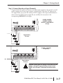
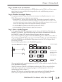
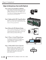
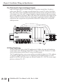
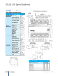
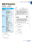
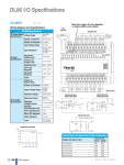
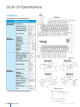
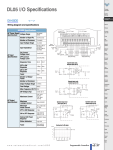
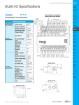
Chapter 1: Getting Started
Quick Start
This example is not intended to tell you everything you need to know about programming
and starting-up a complex control system. It is only intended to give you an opportunity to
demonstrate to yourself and others the basic steps necessary to power up the PLC and
confirm its operation. Please look for warnings and notes throughout this manual for
important information you will not want to overlook.
Step 1: Unpack the DL06 Equipment
Unpack the DL06 and gather the parts necessary to build this demonstration system. The
recommended components are:
• DL06 Micro PLC
• AC power cord or DC power supply
• Toggle switches (see Step 2 on next page).
• Hook-up wire, 16-22 AWG
• DL06 User Manual (this manual)
• A small screwdriver, 5/8” flat or #1 Philips type
You will need at least one of the following programming options:
• DirectSOFT32 Programming Software V4.0 or later (PC-PGMSW or PC-PGM-BRICK),
DirectSOFT32 Manual (included with the software), and a programming cable (D2-DSCBL
connects the DL06 to a personal computer)
or
• D2-HPP Handheld Programmer, firmware version 2.20 or later, (comes with programming cable).
Please purchase Handheld Programmer Manual D2-HPP-M separately.
0V
LG
Y0
Y2
C1
Y5
Y7 Y10 Y12
C3 Y15 Y17
G
AC(L) AC(N) 24V C0
Y1
Y3
Y4
Y6
C2
Y11 Y13 Y14 Y16 N.C.
OUTPUT: 6-240V
50 - 60Hz
2.0A, 6 - 27V
2.0A
PWR: 100-240V
0
1
2
3
4
5
6
7
10
11
12
13
14
15
16
PWR
RUN
CPU
TX1
RX1
TX2
RX2
50-60Hz 40VA
Y
17
20
D0-06DR
21 22
23
X
INPUT: 12 - 24V
3 - 15mA
LOGIC
06
K oyo
C0
X1
X0
X3
X2
X4
C1
X6
X5
X7
C2 X11 X13 X14 X16 C4 X21 X23 N.C.
X10 X12 C3
X15 X17 X20 X22 N.C.
TERM
PORT1
1–6
PORT2
RUN STOP
DL06 Micro PLC User Manual; 1st Ed., Rev. A, 10/02
Chapter 1: Getting Started
Step 2: Connect Switches to Input Terminals
To proceed with this quick-start exercise or to follow other examples in this manual, you will
need to connect one or more input switches as shown below. If you have DC inputs on an
AC-supply DL06, you can use the auxiliary 24VDC supply on the output terminal block or
other external 12-24VDC power supply. Be sure to follow the instructions in the
accompanying WARNING on this page.
D0-06DA, D0-06DD1,
D0-06DD2, D0-06DR,
D0-DD1-D, and D0-06DR1-D
DC Input
06
LOGIC
K oyo
C0
X1
X0
X3
X2
X4
C1
X6
X5
X7
C2 X11 X13 X14 X16 C4 X21 X23 N.C.
X15 X17 X20 X22 N.C.
X10 X12 C3
12 - 24 VDC
+
Toggle Switches
UL Listed
D0-06AA and D0-06AR
AC input only
LOGIC
06
K oyo
C0
X1
X0
X3
X2
X4
C1
X6
X5
X7
C2 X11 X13 X14 X16 C4 X21 X23 N.C.
X15 X17 X20 X22 N.C.
X10 X12 C3
fuse
90 - 120 VAC
Toggle Switches
UL Listed
WARNING: Remove power and unplug the DL06 when wiring the
switches. Use only UL-approved switches rated for at least
250VAC, 1A for AC inputs. Firmly mount the switches before
using.
DL06 Micro PLC User Manual; 1st Ed., Rev. A, 10/02
1–7
Chapter 1: Getting Started
Step 3: Connect the Power Wiring
Connect the power input wiring for the DL06. Observe all precautions stated earlier in this
manual. For more details on wiring, see Chapter 2 on Installation, Wiring, and Specifications.
When the wiring is complete, close the connector covers. Do not apply power at this time
12 - 24 VDC
-
Fuse
Fuse
+
fuse
110/220 VAC Power Input
12/24 VDC Power Input
G
LG
Y0
Y2
C1
Y5
Y7 Y1
0V
AC(L) AC(N) 24V C0
Y1
Y3
Y4
Y6
C2
OUTPUT: 17-240V
50 - 60Hz
0.5A
PWR: 100-240V
50-60H
G
1
2
3
4
5
6
7
10
11
12
13
14
N.C. Y0
Y2
C1
Y5
Y7 Y10 Y1
N.C. C0
Y1
Y3
Y4
Y6
C2
Y11
6 - 27V
1.0A
PWR: 12-24
20W
Y
15
0
X
INPUT: 90 - 120V
-
OUTPUT: Sinking Output
Y
0
LG
+
1
2
3
4
5
6
7
10
11
12
13
14
15
X
7 - 15mA
INPUT: 12 - 24V
3 - 15mA
Step 4: Connect the Programming Device
Most programmers will use DirectSOFT32 programming software, Version 4.0 or later,
installed on a personal computer. An alternative, if you need a compact portable
programming device, is the Handheld Programmer (firmware version 2.20 or later). Both
devices will connect to COM port 1 of the DL06 via the appropriate cable.
0V
LG
Y0
Y2
C1
Y5
Y7 Y10 Y12
C3 Y15 Y17
G
AC(L) AC(N) 24V C0
Y1
Y3
Y4
Y6
C2
Y11 Y13 Y14 Y16 N.C.
OUTPUT: 6-240V
Y
X
0
1
2
50 - 60Hz
3
INPUT: 12 - 24V
4
5
2.0A, 6 - 27V
6
7
10
2.0A
11
12
PWR: 100-240V
13
14
15
16
PWR
RUN
CPU
TX1
RX1
TX2
RX2
50-60Hz 40VA
17
20
D0-06DR
21 22
23
3 - 15mA
LOGIC
C0
06
K oyo
X1
X0
X3
X2
X4
C1
X6
X5
X7
C2 X11 X13 X14 X16 C4 X21 X23 N.C.
X15 X17 X20 X22 N.C.
X10 X12 C3
TERM
PORT1
PORT2
RUN STOP
Use cable part #
D2–DSCBL
(cable comes with HPP)
0V
LG
Y0
Y2
C1
Y5
Y7 Y10 Y12
C3 Y15 Y17
G
Y1
Y3
Y4
Y6
C2
Y11 Y13 Y14 Y16 N.C.
AC(L) AC(N) 24V C0
OUTPUT: 6-240V
Y
X
0
1
2
50 - 60Hz
3
INPUT: 12 - 24V
4
5
2.0A, 6 - 27V
6
7
10
2.0A
11
12
PWR: 100-240V
13
14
15
16
PWR
RUN
CPU
TX1
RX1
TX2
RX2
50-60Hz 40VA
17
20
D0-06DR
21 22
23
3 - 15mA
LOGIC
C0
06
K oyo
X1
X0
X3
X2
X4
C1
X6
X5
X7
C2 X11 X13 X14 X16 C4 X21 X23 N.C.
X10 X12 C3
X15 X17 X20 X22 N.C.
TERM
PORT1
PORT2
For replacement
cable, use part #
DV–1000CBL
RUN STOP
Note: The Handheld Programmer cannot create or access LCD, ASCII or MODBUS instructions.
1–8
DL06 Micro PLC User Manual; 1st Ed., Rev. A, 10/02
16
Chapter 1: Getting Started
Step 5: Switch on the System Power
Apply power to the system and ensure the PWR indicator on the DL06 is on. If not, remove
power from the system and check all wiring and refer to the troubleshooting section in
Chapter 9 for assistance.
Step 6: Initialize Scratchpad Memory
It’s a good precaution to always clear the system memory (scratchpad memory) on a new
DL06. There are two ways to clear the system memory:
• In DirectSOFT32, select the PLC menu, then Setup, then Initialize Scratchpad. For additional
information, see the DirectSOFT32 Manual. Initializing Scratchpad will return secondary comm
port settings and retentive range settings to default. If you have made any changes to these you will
need to note these changes and re-enter them after initializing Scratchpad.
• For the Handheld Programmer, use the AUX key and execute AUX 54.
See the Handheld Programmer Manual for additional information.
Step 7: Enter a Ladder Program
At this point, DirectSOFT32 programmers need to refer to the Quick Start Tutorial in the
DirectSOFT32 Manual. There you will learn how to establish a communications link with
the DL06 PLC, change CPU modes to Run or Program, and enter a program.
If you are learning how to program with the Handheld Programmer, make sure the CPU is in
Program Mode (the RUN LED on the front of the DL06 should be off ). If the RUN LED is
on, use the MODE key on the Handheld Programmer to put the PLC in Program Mode,
then switch to TERM.
Enter the following keystrokes on the Handheld Programmer.
Equivalent DirectSOFT32 display
X0
CLR
C
Y0
OUT
E
2
NEXT
Clear the Program
CLR
4
AUX
$
ENT
A
STR
0
ENT
ENT
END
A
GX
OUT
SHFT
0
E
4
N
TMR
3
Move to the first
address and enter
X0 contact
Enter output Y0
ENT
D
CLR
ENT
Enter the END
statement
After entering the simple example program put the PLC in Run mode by using the Mode key
on the Handheld Programmer.
The RUN indicator on the PLC will illuminate indicating the CPU has entered the Run
mode. If not, repeat this step, ensuring the program is entered properly or refer to the
troubleshooting guide in chapter 9.
After the CPU enters the run mode, the output status indicator for Y0 should follow the
switch status on input channel X0. When the switch is on, the output will be on.
DL06 Micro PLC User Manual; 1st Ed., Rev. A, 10/02
1–9
Chapter 1: Getting Started
Steps to Designing a Successful System
Step 1: Review the Installation Guidelines
Always make safety the first priority in any system
design. Chapter 2 provides several guidelines that
will help you design a safer, more reliable system.
This chapter also includes wiring guidelines for the
various versions of the DL06 PLC.
Step 2: Understand the PLC Setup Procedures
The PLC is the heart of your automation system.
Make sure you take time to understand the various
features and setup requirements.
Step 3: Review the I/O Selection Criteria
There are many considerations involved when you
select your I/O type and field devices. Take time to
understand how the various types of sensors and
loads can affect your choice of I/O type.
+
Input
Sensing
–
Common
Step 4: Choose a System Wiring Strategy
It is important to understand the various
system design options that are available before
wiring field devices and field-side power
supplies to the Micro PLC.
PLC
Input
AC
Power
Loads
DL06
PLC
Power Input
+24 VDC
+
16 Outputs
Commons
20 Inputs
Commons
–
Step 5: Understand the System Operation
Before you begin to enter a program, it is very
helpful to understand how the DL06 system
processes information. This involves not only
program execution steps, but also involves the
various modes of operation and memory
layout characteristics.
1–10
DL06 Micro PLC User Manual; 1st Ed., Rev. A, 10/02
Power Up
Initialize Hardware
Chapter 1: Getting Started
Step 6: Review the Programming Concepts
The DL06 PLC instruction set provides for three main approaches to solving the application
program, depicted in the figure below.
• RLL diagram-style programming is the best tool for solving boolean logic and general CPU
register/accumulator manipulation. It includes dozens of instructions, which will also be needed to
augment drums and stages.
• The Timer/Event Drum Sequencer features up to 16 steps and offers both time and/or event-based
step transitions. The DRUM instruction is best for a repetitive process based on a single series of
steps.
• Stage programming (also called RLLPlus) is based on state-transition diagrams. Stages divide the
ladder program into sections which correspond to the states in a flow chart you draw for your
process.
Standard RLL Programming
(see Chapter 5)
X0
Timer/Event Drum Sequencer
(see Chapter 6)
Stage Programming
(see Chapter 7)
Push–UP
LIGHT
DOWN
CMPD
K309482
SP62
RAISE
LDD
V1076
Y0
OUT
LOWER
UP
Push–
DOWN
After reviewing the programming concepts above, you’ll be equipped with a variety of tools to
write your application program.
Step 7: Choose the Instructions
Once you have installed the Micro PLC and
understand the main programming concepts, you
can begin writing your application program. At
that time you will begin to use one of the most
powerful instruction sets available in a small PLC.
TMR
T1
K30
CNT
CT3
K10
Step 8: Understand the Maintenance and
Troubleshooting Procedures
Sometimes equipment failures occur when we least
expect it. Switches fail, loads short and need to be
replaced, etc. In most cases, the majority of the
troubleshooting and maintenance time is spent
trying to locate the problem. The DL06 Micro
PLC has many built-in features such as error codes
that can help you quickly identify problems.
DL06 Micro PLC User Manual; 1st Ed., Rev. A, 10/02
1–11
Chapter 2: Installation, Wiring, and Specifications
Class 1, Division 2 Approval
This equipment is suitable for use in Class 1, Division 2, groups A, B, C and D or nonhazardous locations only.
WARNING: Explosion Hazard! Substitution of components may impair suitability for Class 1, Division 2.
Do not disconnect equipment unless power has been switched off or area is known to be nonhazardous.
Orientation to DL06 Front Panel
Most connections, indicators, and labels on the DL06 Micro PLCs are located on its front
panel. The communication ports are located on front of the PLC as are the option card slots
and the mode selector switch. Please refer to the drawing below.
Power Inputs
Mounting Tab
Discrete Outputs
Output Status
Indicators
Output Circuit
Power Input
(for DC output versions only)
Status
Indicators
G
LG
Y0
Y2
C1
Y5
Y7 Y10 Y12
C3 Y15 Y17
0V
AC(L) AC(N) 24V C0
Y1
Y3
Y4
Y6
C2
Y11 Y13 Y14 Y16 N.C.
OUTPUT: 6-240V
50 - 60Hz
2.0A, 6 - 27V
2.0A
PWR: 100-240V
Y
0
1
2
3
4
5
6
7
10
11
12
13
14
15
16
17
20
D0-06DR
21 22
23
X
INPUT: 12 - 24V
Communication
Ports
3 - 15mA
LOGIC
PWR
RUN
CPU
TX1
RX1
TX2
RX2
50-60Hz 40VA
06
K oyo
C0
X1
X0
X3
X2
X4
C1
X6
X5
X7
C2 X11 X13 X14 X16 C4 X21 X23 N.C.
X15 X17 X20 X22 N.C.
X10 X12 C3
TERM
PORT1
Discrete Inputs
Input Status
Indicators
Option Slots
PORT2
RUN STOP
Mode Switch
Mounting Tab
The output and power connector accepts external power and logic and chassis ground
connections on the indicated terminals. The remaining terminals are for connecting
commons and output connections Y0 through Y17. The sixteen output terminals are
numbered in octal, Y0-Y7 and Y10-Y17. On DC output units, the end terminal on the right
accepts power for the output stage. The input side connector provides the location for
connecting the inputs X0 and X23 and the associated commons.
WARNING: For some applications, field device power may still be present on the terminal block even
though the Micro PLC is turned off. To minimize the risk of electrical shock, check all field
device power before you expose or remove either connector
2–4
DL06 Micro PLC User Manual; 1st Ed., Rev. A, 10/02
Chapter 2: Installation, Wiring, and Specifications
Fuse Protection for Input and Output Circuits
Input and Output circuits on DL06 Micro PLCs do not have internal fuses. In order to
protect your Micro PLC, we suggest you add external fuses to your I/O wiring. A fast-blow
fuse, with a lower current rating than the I/O bank’s common current rating can be wired to
each common. Or, a fuse with a rating of slightly less than the maximum current per output
point can be added to each output. Refer to the Micro PLC specification sheets further in this
chapter to find the maximum current per output point or per output common. Adding the
external fuse does not guarantee the prevention of Micro PLC damage, but it will provide
added protection.
0V
LG
Y0
Y2
C1
Y5
Y7 Y10 Y12
C3 Y15 Y17
G
AC(L) AC(N) 24V C0
Y1
Y3
Y4
Y6
C2
Y11 Y13 Y14 Y16 N.C.
OUTPUT: 6-240V
Y
X
0
1
2
50 - 60Hz
3
INPUT: 12 - 24V
4
5
2.0A, 6 - 27V
6
7
10
2.0A
11
12
PWR: 100-240V
13
14
15
16
PWR
RUN
CPU
TX1
RX1
TX2
RX2
50-60Hz 40VA
17
20
D0-06DR
21 22
23
3 - 15mA
LOGIC
C0
06
K oyo
X1
X0
X3
X2
X4
C1
X6
X5
X7
C2 X11 X13 X14 X16 C4 X21 X23 N.C.
X15 X17 X20 X22 N.C.
X10 X12 C3
TERM
PORT1
PORT2
RUN STOP
I/O Point Numbering
All DL06 Micro PLCs have a fixed I/O configuration. It follows the same octal numbering
system used on other DirectLogic family PLCs, starting at X0 and Y0. The letter X is always
used to indicate inputs and the letter Y is always used for outputs.
The I/O numbering always starts at zero and does not include the digits 8 or 9. The addresses
are typically assigned in groups of 8 or 16, depending on the number of points in an I/O
group. For the DL06 the twenty inputs use reference numbers X0 – X23. The sixteen output
points use references Y0 – Y17.
2–12
DL06 Micro PLC User Manual; 1st Ed., Rev. A, 10/02
Chapter 2: Installation, Wiring, and Specifications
D0–06DD1–D I/O Wiring Diagram
These micro PLCs feature twenty DC inputs and sixteen sinking DC outputs. The following
diagram shows a typical field wiring example. The DC external power connection uses four
terminals at the left as shown.
Inputs are organized into five banks of four. Each bank has an isolated common terminal, and
may be wired as either sinking or sourcing inputs. The wiring example below shows all
commons connected together, but separate supplies and common circuits may be used.
All outputs actually share the same common. Note the requirement for external power.
12 - 24 VDC
-
+
+24 VDC
L L L L
G
LG
+
-
OUTPUT: Sinking Output
L L L L
L L L L
L L L L
Y2
C1
Y5
Y7 Y10 Y12
C3 Y15 Y17
N.C. Y0
Y1
Y3
Y4
Y6
C2
Y11 Y13 Y14 Y16 +V
N.C. C0
6 - 27V
1.0A
PWR: 12-24
20W
D0-06DD1-D
Y
0
1
2
3
+
4
5
6
7
10
11
12
13
14
15
16
17
20
21 22
23
X
INPUT: 12 - 24V
3 - 15mA
LOGIC
06
K oyo
C0
X1
X0
X3
X2
X4
C1
X6
X5
X7
C2 X11 X13 X14 X16 C4 X21 X23 N.C.
X15 X17 X20 X22 N.C.
X10 X12 C3
DC
Supply
Internal module circuitry +V
+V
+V
Optical
Isolator
Input
+
+
24VDC
OUTPUT
L
To LED
Optical
Isolator
+ 6–27
VDC
–
Common
To LED
COM
DC Pulse Outputs (Y0 - Y1)
High Speed Inputs (X0-X3)
Points
+V
Input
+
+V
16
+V
1.0 A
Y0 - Y7
Y10 - Y17
12
Optical
Isolator
24VDC
8
To LED
4
L
0
–
0
32
Common
Internal module circuitry
+
10
50
20
68
30
86
40
104
50
122
50˚C
122˚C
OUTPUT
Optical
Isolator
To LED
+ 6–27
VDC
Ambient Temperature ( ˚C/ ˚F)
COM
Standard Input Circuit (X4-X23)
2–38
Derating Chart for DC Outputs
DL06 Micro PLC User Manual; 1st Ed., Rev. A, 10/02
DC Standard Outputs (Y2 - Y17)
Chapter 2: Installation, Wiring, and Specifications
D0-06DD1-D General Specifications
External Power Requirements
Communication Port 1: 9600 baud (Fixed),
8 data bits, 1 stop bit, odd parity
Communication Port 2: 9600 baud (default),
8 data bits, 1 stop bit,odd parity
Programming cable type
Operating Temperature
Storage Temperature
Relative Humidity
Environmental air
Vibration
Shock
Noise Immunity
Terminal Type
Wire Gauge
12 – 24 VDC, 20 W maximum,
K–Sequence (Slave), DirectNET (Slave),
MODBUS (Slave)
K–Sequence (Slave), DirectNET (Master/Slave),
MODBUS (Master/Slave), Non-sequence/print, ASCII in/out
D2–DSCBL
32 to 131° F (0 to 55 C)
–4 to 158° F (–20 to 70 C)
5 to 95% (non-condensing)
No corrosive gases permitted
MIL STD 810C 514.2
MIL STD 810C 516.2
NEMA ICS3–304
Removable
One AWG16 or two AWG18, AWG24 minimum
DC Input Specifications
Parameter
Min. - Max. Voltage Range
Operating Voltage Range
Peak Voltage
Minimum Pulse Width
ON Voltage Level
OFF Voltage Level
Max. Input Current
Input Impedance
Minimum ON Current
Maximum OFF Current
OFF to ON Response
ON to OFF Response
Status Indicators
Commons
High–Speed Inputs, X0 – X3
Standard DC Inputs X4 – X23
10.8 – 26.4 VDC
10.8 – 26.4 VDC
12 – 24 VDC
12 – 24 VDC
30 VDC (7 kHz maximum frequency)
30 VDC
70 µs
N/A
>10.0 VDC
> 10.0 VDC
< 2.0 VDC
< 2.0 VDC
6mA @12VDC, 13mA @24VDC
4mA @12VDC, 8.5mA @24VDC
1.8 k @ 12 – 24 VDC
2.8 k @ 12 – 24 VDC
>5 mA
>4 mA
< 0.5 mA
<0.5 mA
<70 µS
2 – 8 mS, 4 mS typical
<70 µS
2 – 8 mS, 4 mS typical
Logic side
Logic side
4 channels / common x 5 banks (isolated)
DC Output Specifications
Parameter
Min. - Max. Voltage Range
Operating Voltage
Peak Voltage
On Voltage Drop
Max Current (resistive)
Max leakage current
Max inrush current
External DC power required
OFF to ON Response
ON to OFF Response
Status Indicators
Commons
Fuses
Pulse Outputs, Y0 – Y1
Standard Outputs, Y2 – Y17
5 – 30 VDC
5 – 30 VDC
6 – 27 VDC
6 – 27 VDC
< 50 VDC (10 kHz max. frequency)
< 50 VDC
0.3 VDC @ 1 A
0.3 VDC @ 1 A
0.5 A / pt., 1A / pt. as standard pt.
1.0 A / point
15 µA @ 30 VDC
15 µA @ 30 VDC
2 A for 100
mS 2 A for 100 mS
20 - 28 VDC Max 150mA
20 - 28 VDC Max 150mA
< 10 µs
< 10 µs
< 20 µs
< 60 µs
Logic Side
Logic Side
4 channels / common x 4 banks (non-isolated)
None (external recommended)
DL06 Micro PLC User Manual; 1st Ed., Rev. A, 10/02
2–39