1
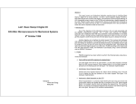
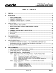
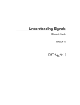
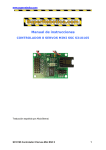
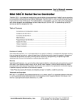
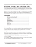
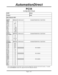
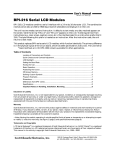
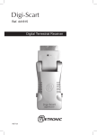
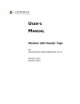
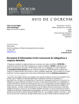
DECADE ENGINEERING
5504 ValView Dr. SE, Turner, OR 97392-9517 (USA) ~ tel: 503.743.3194 ~ fax: 503.743.2095
email: [email protected] ~ web site: www.decadenet.com
BOB-II FAQ & Discussion
June 6, 2001 ~ Please discard earlier versions!
How can I get BOB-II working quickly?
Refer to the basic hookup diagrams below. Also build the simple RS-232 receive interface described in another FAQ topic (Why
does the data have to be inverted? further below) and connect it to the COM port of a PC. Launch HyperTerminal or equivalent
and configure it for 9600 8N1, no handshake, plain ASCII terminal emulation. Power up BOB-II and type. Characters appear at
the upper left corner of your TV monitor screen!
30-pin SIMM Socket
1
2
3
4
5
6
7
8
9
10
11
12
13
14
15
16
17
18
19
20
21
22
23
24
25
26
27
28
29
30
BOB-II
VIDEO IN
V+12
(OPTIONAL)
RES
IN
GND
GND
MC34164P-5
1
2
3
DATA IN
VIDEO OUT
.001uF
Figure 1: Basic BOB-II Hookup
Figure 2: MC34164P-5 Brownout Detector IC Pinout
It’s important to use a brownout detector circuit at the reset pin (10). There’s more information on this topic in the discussion
about BOB-II start-up problems and reset pin management.
The BOB-II Control Protocol spec is too terse. Where can I get an application program example?
BOB-II application program examples are available for download at Decade’s web site: www.decadenet.com. Go to the Products
page, then click on BOB-II. Scroll down the BOB-II page to find the download links. Here’s a simple BOB-II test program for a
PC running MS QuickBASIC:
Decade Engineering BOB-II FAQ ~ Page 1
OPEN "com1: 9600,n,8,1,cs0,ds0,cd0,op1000,rs" FOR OUTPUT AS #1
PRINT #1, "{A"; 'Clear the display (pause required...)
FOR x = 1 TO 425: NEXT 'About 5mS time delay on a 486DX2-66 (interpreting)
PRINT #1, "BOB-II Test Program 12345678";
PRINT #1, "{Tzz||}}{{"; CHR$(27); " Do you see arrows?";
PRINT #1, "{C0505Row 5 - Column 5{C0506{T|"; CHR$(27); "{C0504{T}"; CHR$(27);
CLOSE #1
How much current can I really get from the +5V output (pin 3)?
BOB-II uses a 78M05 type regulator IC to derive its internal operating voltage from the raw power supply at pin 1. Its heat
dissipation capabilities are modest, but far in excess of 78L05 types. BOB-II consumes about 65mA internally. The spec sheet
gives 50mA as a maximum load on pin 3, but this may be doubled if ambient temperature isn’t excessive. If you need to press the
limit, refer to the 78M05 spec sheet (published elsewhere). Also be aware that the power supply input filter capacitor carries a
25V maximum rating, which must be derated if operating temperature is elevated.
Why does the data have to be inverted?
BOB-II expects inverted serial data at pin 7, with 5V logic levels. This allows a direct connection to the UART transmit output
pin of any standard microcontroller, but you need an inverting receive interface if you’re going to connect to the COM port of a
PC or any ‘true’ RS-232 circuit. MAX232 style interface chips are the industry-standard solution. You probably should go ahead
and use one if you’re running a long data cable, because it conveniently provides features that maximize noise immunity. If your
hookup is short and direct, you can abbreviate this requirement to a simple transistor inverter stage as shown below. The RS-232
Receive Input line connects to pin 3 of a 9-pin PC COM port (TX Out). Pin 5 of the PC COM port connects to Ground. Use
BOB-II pin 3 for the V+5 power source:
V+5
R2
4.7K
RS-232
RECEIVE
INPUT
R1
10K
Q1
2N3904
TO BOB-II
DATA
INPUT PIN
D1
1N4148
Figure 3: Simple RS-232 Receive interface
Be aware that some PC serial cables are not wired straight-through (modem style), but instead swap the TX/RX and control
signal pins. These are sometimes sold as serial printer or ‘null-modem’ cables.
BOB-II works correctly with my PC, but displays gibberish with my BASIC Stamp. Why?
The Parallax PBASIC documentation for SEROUT views data polarity in a sense opposite to that which Decade Engineering
adopted in the BOB-II documentation. This is true for both BS1 and BS2 as of February 2000. Therefore, use Baudmode
expression ‘T2400’ in your BS1 program (2400bps is the only compatible rate for BS1). The BS2 argument for SEROUT at
9600bps, for example, would have Baudmode set to 84 or 85. This discussion assumes a ‘straight wire’ data connection.
Be aware that BOB-II and the BASIC Stamps both use ceramic resonators to control baud rate. Accuracy limitations of these
timing devices are such that baud rate mismatch can occur when they’re used at both ends of a serial com link. Try small baud
rate changes in your Stamp program if nothing else works!
Do I have to provide a video signal to pin 30?
You don’t have to supply video to this input pin. BOB-II generates background video internally if you don’t. When a video signal
is supplied, BOB-II genlocks to it and superimposes characters. A command has been provided to force local video generation
while video is supplied to the input pin, but it shouldn’t be used if a transparency control is installed.
Decade Engineering BOB-II FAQ ~ Page 2
If you’re using the video input, supply it with clean composite baseband (not RF) video from a source that delivers 1Vpp into a
75Ω termination. That’s the most common type. BOB-II provides a correct input termination. Many video device outputs contain
some incidental DC bias voltage, because it’s awkward to design video circuits to operate on a single supply voltage any other
way. It’s unlikely, but if you measure DC bias greater than +2.5V at pin 30, you must find a way to reduce or eliminate it because
BOB-II may suffer damage due to reverse-bias on the input coupling capacitor. A typical solution would be to insert a large
electrolytic blocking capacitor, 470uF or greater, in series with the video line to BOB-II’s input pin.
How can I make the overlay transparent? & What are all those video outputs for?
CVO2, pin 23, is an auxiliary unbuffered video output with no character overlay. It’s possible to connect a 2~5K pot across
CVO1 and CVO2, with its wiper returned to EF IN, and achieve a text overlay effect with fully adjustable transparency. Be aware
that video crosstalk can appear if you implement this feature and command local video mode while supplying an external video
source to BOB-II. This feature was not operational in early shipments of BOB-II. Contact Decade Engineering if you need an
update.
BOB-II offers a number of video output options. CVO1, pin 24, is the basic unbuffered video output. CVO1 is DC coupled and
offset positive by 2~3V. This pin cannot drive coaxial cable, so a power buffer circuit with source termination was provided at
pin 26 (input) and pin 28 (output). The buffer is an emitter-follower with no output DC blocking capacitor. When correctly
terminated downstream (in 75Ω), it biases the video signal to about +1VDC. An external capacitor may be wired in series with
pin 28 to block DC bias, but it’s very rarely needed. If you don’t want to use the buffer, you can eliminate its power consumption
(>10mA) by tying pin 26 to ground. Composite SYNC, available at pin 20, may be used to derive a clamp pulse for DC
restoration in external video processing circuits.
How can I use external video level (brightness) control?
CLVL (pin 21) and SLVL (pin 22) are provided for applications where it’s desirable to make character or background brightness
variable. Because {HX and {HN (see command protocol) switch CLVL and SLVL simultaneously, you must manage DC levels
at both pins if you need to use either of them. We suggest 2KΩ pots, each with a 2K resistor at the CW (clockwise) end
connected to V+5 and 1K at the CCW end to ground. Bypass each pot wiper terminal with 0.1uF to ground at BOB-II pins 21and
22. More restricted voltage ranges are appropriate if non-experts will be operating the end equipment.
How can I display the arrow symbols (or any of the graphics characters) ?
Invoke no-translate mode by sending {T, then send the literal codes listed in the character set documentation. Send 7A~7D hex,
122~125 decimal, or ASCII z, {, |, or } to display the arrow symbols. Always terminate your {T command string with an
<ESC> character. Examples: {Tz<ESC> displays the right-arrow, {T|||<ESC> displays three up-arrows. {Tz{|}<ESC>
would display all four arrow symbols in a row. <ESC> is a single character, coded as 1B hex (27 decimal) which can be sent
from a PC keyboard with the Escape key or the Control plus '[' key combination. Note that upper-case P in no-translate mode is
coded as 1B hex, which is identical to the ASCII <ESC> code. Since <ESC> is the command termination character for notranslate mode, BOB-II switches back to normal ASCII translate mode instead of printing a P. Your application program should
use the normal ASCII translation mode of BOB-II for displaying text. Also, be aware that the current (v1.2) BOB-II firmware
suppresses automatic video mode switching while a {T command is executing. The {T command was intended to be used with
short strings of special characters which would otherwise be unavailable.
Can I insert BOB-II in a cable TV system and display the same text on all channels at once?
This isn’t possible for a number of reasons. In a cable system, video signals are modulated onto RF carriers at numerous different
frequencies (that’s why the TV tuner is able to pick out just one). The signals often originate at widely separated locations with
no regard for scan synchronization, and individual signal strengths may be poorly controlled.
BOB-II’s input and output are both baseband video. This means that incoming TV channels must be demodulated from RF to
baseband if you wish to place a text overlay on the image. To display the output from BOB-II on a standard TV receiver, you
must use an RF modulator to re-create a TV broadcast channel, which may then be fed into your cable system for distribution to
as many TV sets as required. Each TV set must be tuned to the modulator's output channel in order to view the text.
Of course, you need a demodulator, a BOB-II, and a modulator for each TV channel requiring a text overlay. A side-benefit of
this arrangement is that you may freely restructure channel assignments in your local cable system. A potential problem is that
Decade Engineering BOB-II FAQ ~ Page 3
low-cost modulators are often poorly filtered and may generate interference on adjacent channels. Be sure to use modulators that
are designed for adjacent channel operation, or else leave dead channels between the ones that are in service.
In home automation systems, it’s often practical to assign just one TV channel for messages from your system controller. Provide
some sort of annunciator to get the user’s attention when important messages are generated, and leave it at that.
Why doesn’t BOB-II start up correctly? ~or~ What do I need to know about BOB-II reset pin management?
If you have to cycle the power supply multiple times to get BOB-II working correctly, it may be an indication that supply voltage
rise takes too long (or isn’t sufficiently linear). This problem has been reported most often in connection with cheap “wall-wart”
power supplies. Possible solutions: Switch the DC supply line, reduce power supply filter capacitance, or reduce series resistance.
The Atmel AVR series CPU in BOB-II may also fail to reset properly if its power supply voltage is not allowed to decay all the
way to zero before switching on. A small dummy load resistor at pin 3 should help if this becomes problematic in your system.
Important Note: In all applications, particularly when power supply voltage decays slowly at turn-off time, a micro-manager or
low-voltage (brownout) detector IC must control BOB-II’s reset pin. Examples of acceptable LV detector ICs: Motorola
MC34164P-5 (no delay); Dallas DS1233-10 (delayed). An off-board pullup resistor is not required.
EMI (electrical noise) could cause unwanted CPU resets if picked up by the reset pin. The recommended bypass capacitor
prevents this “antenna” action and permits external CPU reset control as described in the note above.
What are pins 17~19 used for?
Along with RES\ (pin 10), these pins are used to configure and test BOB-II at the factory. Hackers and engineering professionals
will deduce other possibilities that are beyond the scope of this document. Let it suffice to say that Decade Engineering will assist
qualified organizations with specialized applications under the terms of a legal non-disclosure agreement.
What is “Genlock?”
Genlock is the capability of synchronizing to an external video signal source (generator). To overlay text on video, BOB-II has to
extract scan timing information (sync) from incoming video and use it to synthesize all required internal video timing. These
internal timing signals control the exact placement of visible dots that form character shapes in the display.
Can you suggest part numbers for compatible SIMM sockets?
Molex part numbers are 15-46-3053 (Tin), and 15-46-3043 (Gold). Amp numbers are 822056-2 (Tin) and 822061-2 (Gold).
Adam Technologies numbers are SIMM-130-VTL (Tin), and SIMM-130-VGL (Gold). Adam-Tech gold sockets are currently
available from Decade Engineering for $1.00 each in any quantity. Note: The reliability of tin-plated contacts can be dramatically
improved by application of widely available (Caig Laboratories, Nye Lubricants, etc.) contact treatments.
Why does the text overlay jitter?
This trouble symptom is universally caused by weak and/or noisy video applied to pin 30. Typically, the video signal has been
attenuated by passage through a long cable (or double termination). The best cure for long cable woes is a robust cable drive
amplifier with pre-equalization for cable loss characteristics. Decade Engineering offers a Camera Adapter Board (CAB) with
broad adjustment ranges and high drive capability for this purpose. A Cable Compensator or Video Processor at the receiving end
may also be acceptable. Bear in mind that long cables are subject to noise injection from a variety of sources, including ground
loops, so cable receiver circuits may have to deal with several kinds of signal defect simultaneously.
Why does BOB-II miss or mangle incoming characters after a video mode change (or at power-up time)?
BOB-II is effectively off-line for an indeterminate period of time during video mode changes. This interval can be up to a few
(3~4) seconds when entering Genlock/Overlay mode, but it’s normally insignificant when switching to Local mode. If your
application relies on automatic mode switching to maintain constant video output, then your host controller should monitor pin 15
and take appropriate action. In general, this means refreshing the display if any data was sent during a mode change event.
Display data already in BOB-II RAM will not be corrupted.
Decade Engineering BOB-II FAQ ~ Page 4
In a few applications, automatic video mode switching has been found undesirable because of the stabilization time required by
BOB-II when re-entering Genlock/Overlay mode. Please contact Decade Engineering for a special firmware version in this case.
What is the Reset Flag output (pin 14) for?
This pin may be used to inform the host processor that a local CPU reset was forced by watchdog time-out. In applications where
the video display contains fixed (label) fields along with dynamically updated data fields, a spurious reset in BOB-II effectively
erases the labels. The host processor can refresh these fields, but only if it’s aware that BOB-II got into trouble! Use an external
latch or timer circuit (to extend the pulse) if your host cannot guarantee polling this pin at 10mS or smaller intervals.
What colors correspond to the color number fields in the BOB-II command protocol?
Black is color numbers 0 and 7. Blue is 1 and 5. Red is 4. What color is 3? Is it olive? Is 6 brown? The manufacturer of the
character generator chip we use in BOB-II is vague about this issue in their product literature. The truth is (probably) that the
colors originate in a simple subcarrier delay line rather than a 'real' chroma modulator circuit in the chip, so it's impossible to be
precise about the colors you get-- and it varies somewhat from sample to sample. Wish the news was better.
Why did you leave out the comma character?
We had to accept the 'standard' character set that was offered by the character generator IC vendor, because we're not rich enough
to order a custom mask for the character ROM. Perhaps the character set was determined by a high-volume customer with
specific priorities that didn't include a comma, but demanded enough other stuff to fill up ROM space. You might try the tic mark
(') for large number formatting.
How can BOB-II be used in S-Video systems?
S-Video is a method of transmitting video on two wires labeled 'Y' and 'C'. The Y signal is video brightness information (Luma)
mixed with sync. The C wire carries color (Chroma) information, with hue and saturation encoded like the color component of
composite video. S-Video represents a qualitative middle ground between one-wire composite video, as used in TV broadcasting,
and three-wire component video signal transmission schemes.
The simplest method to handle S-Video with BOB-II is to route the Y channel (only) through it. Just bypass your C channel
around BOB-II. We've done this with good results. There's a little color from the underlying video in superimposed characters,
but if color saturation in your source image isn't extreme, the result is entirely acceptable in many applications.
You could use external fast analog switches, controlled by BOB-II, to perform character insertion in S-Video's Y and C channels.
There are a few chips on the market that have been optimized for jobs like this. Linear Technology’s LT1203 is one of our
favorites. Here are a couple of ideas to flesh out this concept. We haven't tried them:
1.
Trick BOB-II into providing an external switch control signal without modifying it. This could be done by feeding a
clipped (or attenuated) version of the Y channel into BOB-II, then using a fast comparator at the video output to extract
character white level transitions (they would stick up above the video level at all times). Disadvantage: Only character
foregrounds would appear in S-Video. Black character outlines would not be present.
2.
Get a switch control signal directly from internal BOB-II signals. The OSD chip has a number of unused outputs that
should do the trick, but extra logic gates may be required. Only one external analog switch would be needed, for the C
channel, and there's a possible hack using a single cheap transistor for this function. Disadvantage: Decade Engineering
doesn’t enforce the warranty on modified boards.
Note that video input and/or output buffers may be required in addition to the analog switches. The clipping circuit mentioned in
[1] may require upstream DC restoration as well.
I get strange results with {JD and other color control commands. What’s going on?
Operation of certain BOB-II color control commands is described incorrectly or incompletely in the first edition of the printed
user manual and BOB-II Control Protocol documents previous to version 1.21. Please download the most current version of the
BOB-II Control Protocol document from our web site, and observe the following:
Decade Engineering BOB-II FAQ ~ Page 5
•
All of the color control commands have global scope except {En, which affects only those characters written subsequent
to each command instance.
•
In {JE mode, for character cells that have been written with background enabled, the background color is controlled by
{Dn, not {In.
•
In {JD mode, the background for the entire character display area (character grid) is black. {Fn still controls screen
color, which is the border surrounding the character display area, but {Dn and {In have no effect. {En affects
(subsequent) character foreground and background colors simultaneously. Character foregrounds are high-luma versions
of background colors. In other words, foreground and background hue for each character is identical; only the higher
video brightness value makes character foregrounds distinct.
•
{JE is the default (power-up) condition.
A final reminder: These commands are useful in Local Mode only. In Genlock/Overlay mode, BOB-II superimposes only
monochrome characters.
What are the differences between NTSC and PAL versions of BOB-II?
In addition to the crystal difference for NTSC vs. PAL chroma subcarrier frequencies (in Local mode), firmware differences
affect OSD control registers and vertical line spacing. Due the greater number of scan lines in PAL systems, it was necessary to
add some ‘padding’ between text rows in order to fill the available screen space. The only negative consequence is that character
bitmaps cannot be vertically contiguous in the PAL version, which means that high-resolution vertical bar graph displays should
not be attempted.
What the heck does “BOB” mean, anyway?
Basic Overlay Board. Too simple, eh?
====O====
Decade Engineering BOB-II FAQ ~ Page 6