1
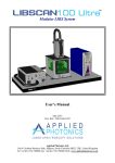
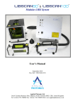
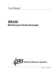
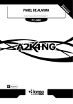
Portable, Modular LIBS Instrument
User’s Manual
May 2012
Doc. Ref.: UM/0218-01/00
Applied Photonics Ltd
Unit 8 Carleton Business Park, Skipton, North Yorkshire BD23 2DE, United Kingdom
Tel +44 (0) 1756 708900 Fax +44 (0) 1756 708909 Web: www.appliedphotonics.co.uk
Contents
1.
Introduction
Page
3
2.
Safety
2.1
Laser radiation
2.2
Note on the laser safety window material used in the modular sample chambers
2.3
Electrical
3
3
6
6
3.
General description
3.1
Overview
3.2
Instrument console and control panel
3.3
LIBSCAN 25+ head
3.4
The integrated pulsed laser
3.5
Laser beam expander and plasma light collection optics
3.6
Imaging camera and associated components
3.7
Attachment of the LIBSCAN 25+ head to an optical table
3.8
Modular sample chambers
7
7
8
8
10
11
12
12
13
4.
General operating procedure
15
5.
Shut-down procedure
20
6.
Maintenance and inspection
20
7.
Shipping and storage
20
8.
Trouble-shooting / fault finding
21
Appendices
A1
A2
Acquiring spectra using LIBSCAN 25+: A brief guide to software configuration
and usage
22
Certificate of Conformity
27
© 2012 Applied Photonics Ltd
Page 2 of 27
1
Introduction
LIBSCAN 25+ is a fully portable LIBS instrument adopting the same modular design principles used in
our LIBSCAN range of products. Suitable for laboratory or field applications, LIBSCAN 25+ operates
from its internal 12 Volt 8Ah Li-Ion battery and can operate for up to 4 hrs from a single charge.
Recharging is achieved using a mains plug-in adaptor Li-Ion charger which is supplied with the
instrument. The six-channel design of LIBSCAN 25+ allows for up to six compact spectrometers to be
installed (approx. 185 – 900 nm), depending upon the requirements of the intended application and
budget limitations. LIBSCAN 25+ can be supplied with an optional integrated netbook computer and/or
an imaging camera for recording close-up video / still images of the sample. LIBSCAN 25+ is, by
design, a Class 4 laser product although when used with one of our range of modular sample chambers
the product meets Class 1 laser safety standards.
This User’s Manual provides the necessary information needed to configure the LIBSCAN 25+
instrument and how to use it safely. It is assumed that the user will be familiar with the safety issues
arising from the use of high-power lasers and will have preferably been trained in the safe use of highpower laser products.
2
Safety
2.1
Laser radiation
LIBSCAN 25+ contains a high-power Q-switched Nd:YAG laser (Class 4, nominally 50 mJ @ 1064 nm,
5 ns pulse length, 1 Hz pulse repetition rate) and so it is imperative that it is operated only by suitably
trained and experienced persons who are fully aware of the hazards inherent to this type of high-power
laser equipment. It is imperative also that, prior to using the equipment, an appropriate risk assessment is
conducted in such a way as to take account of the proposed use of the equipment, the environment in
which the equipment is to be operated, and how its use may affect people who are not directly involved
with the use of the equipment.
LIBSCAN 25+ is designed to meet the laser safety requirements of the relevant European standards (BS
EN 60825) and USA standards (ANSI Z136.1 – 2007). Although LIBSCAN 25+ may be supplied with a
sample chamber which provides adequate containment of the laser radiation to Class 1 Accessible
Emission Limits, it is possible for the user to operate LIBSCAN 25+ without the sample chamber (ie.
operation in “open beam” mode as may be required for certain types of experiment). Accordingly, it is
necessary to consider LIBSCAN 25+ to be a Class 4 Laser Product and so, by definition, the equipment
poses a risk of personal injury (eye, skin injury) and poses a fire risk. As with all Class 4 laser products,
appropriate safety precautions must be taken as identified via a suitable risk assessment conducted by the
user in consultation with a suitably qualified and experienced Laser Safety Officer.
© 2012 Applied Photonics Ltd
Page 3 of 27
The most significant hazard relating to exposure of personnel to the laser radiation is eye injury since
direct or scattered laser radiation produced by LIBSCAN 25+ can cause serious and permanent injury to
the eyes including blindness - such injury may be instantaneous. Precautions must be taken to avoid
exposure of personnel to hazardous levels of laser radiation. Such precautions may include the setting up
of a temporary or permanent laser controlled area (eg. a laser laboratory). Other measures may also be
necessary, as determined by appropriate and thorough assessment of the risks (ie. a risk assessment)
conducted by the personnel responsible for the safe use of the LIBSCAN 25+ instrument.
With the use of an optional adaptor, LIBSCAN 25+ may be used with any one of our range of modular
sample chambers (SC-1, SC-2, etc).
IMPORTANT
•
READ and UNDERSTAND this User’s Manual before operating LIBSCAN 25+
•
NEVER allow unauthorised and/or untrained persons operate LIBSCAN 25+.
•
Only suitably qualified and authorised persons who are trained in the safe use of Class 4 laser
products should be allowed to use LIBSCAN 25+ when the instrument is operated in “open beam”
mode (ie. without an approved sample chamber designed specifically for use with LIBSCAN
25+).
•
ALWAYS use appropriate laser safety protective eyewear when operating LIBSCAN 25+ in
“open-beam” configuration – you should seek advice from your Laser Safety Officer on this
matter.
•
ALWAYS switch the laser off when not in use and remove the key from the laser key switch
located on the control panel of LIBSCAN 25+ to prevent accidental and/or unauthorised
activation.
•
NEVER operate LIBSCAN 25+ in areas where explosive gas mixtures may be present.
•
NEVER operate LIBSCAN 25 with any access cover removed.
•
NEVER use LIBSCAN 25+ to analyse flammable or explosive materials or any other material
which may give rise to flammable / explosive gas mixtures. Activation of the laser under these
conditions could result in an explosion leading to severe personal injury and/or fire hazard.
Remember that the laser radiation and the laser-induced plasma are sources of ignition.
•
NOTE that the transparent acrylic (and the optional black Delrin) nozzle aperture does not provide
any protection to the user against exposure to direct or scattered laser radiation. The function of
the nozzle aperture is described later in this User’s Manual.
•
ALWAYS thoroughly inspect LIBSCAN 25+ for damage prior to use. Particular attention should
be given to the laser safety shutter / trigger guard and, if a sample chamber is used, the laser safety
windows and the electrical safety interlock fitted to the door of the sample chamber.
•
NEVER point the LIBSCAN 25+ head at a person (even with laser switched off), especially
towards the eyes, even if the person is wearing laser safety eyewear. The laser should be
considered “active” unless the laser power supply is deactivated and the safety shutter
located on the LIBSCAN 25+ head is switched to the CLOSED position.
© 2012 Applied Photonics Ltd
Page 4 of 27
Laser aperture
warning label
Laser aperture
Laser shutter / trigger guard
in “closed” position.
Orange warning light not
illuminated
Trigger guard in “closed” position preventing
access to the trigger switch. When the laser
shutter is closed, the trigger switch is
electrically isolated and so the laser will not fire
even if the trigger switch is activated. The laser
shutter provides a mechanical beam stop which
prevents emission of laser radiation under any
circumstances, including a fault condition.
Image of LIBSCAN 25+ head with laser safety shutter in the “closed” position.
Laser shutter / trigger guard in “open”
position. Orange warning light now
illuminated (assuming laser is active)
Trigger guard in the
“open” position allowing
access to the trigger switch
Image of LIBSCAN 25+ head with laser safety shutter in the “open” position.
© 2012 Applied Photonics Ltd
Page 5 of 27
2.2
Note on the laser safety window material used in the modular sample chambers
The laser safety window material fitted to the modular sample chambers is rated as follows:
Laser
Wavelength
(nm)
1064
355
266
USA Standard
ANSI Z 136.1 – 2000
UK & European Standard
BS EN 207:1999
Optical
Density
OD 6
OD 5
OD 3
Protection Level R
(Q-switched laser)
L6
L5
L3
R L6 at 1064 nm indicates a protection level of maximum spectral transmittance of 10-6 at 1064 nm for a
pulsed laser of pulse length 10-9 – 10-7 seconds (ie. a Q-switched laser).
The laser safety windows used in Applied Photonics Ltd’s range of modular sample chambers provide
adequate protection against scattered laser light of wavelength 1064 nm, 355 nm and 266 nm such that
Class 1 Accessible Emission Limits are met if the sample chamber is used correctly and laser pulse
energies are not excessively high (ie. typically less than 250 mJ @ 1064 nm with a 5 - 10 ns pulse length).
Given that the modular sample chambers may be used with a variety of LIBSCAN system (and LIBS-6
and LIBS-8 integrated LIBS modules) configurations, it is the responsibility of the user to conduct a risk
assessment to establish whether or not the laser safety windows provide adequate protection for the
particular laser being used. If in any doubt, you should consult your Laser Safety Officer and/or Applied
Photonics Ltd for advice on this matter.
Warning – the Applied Photonics Ltd modular sample chambers are designed specifically for use
with our LIBSCAN (and our LIBS-6 / LIBS-8 integrated LIBS modules) range of products and
should not be used with any other laser device or product. If in doubt, seek advice from the
manufacturer, Applied Photonics Ltd.
2.3
Electrical
The majority of internal electrical components within the LIBSCAN 25+ instrument operate at a nominal
voltage of 12 VDC at a maximum current of approximately 3.0 Amp. The integrated laser and associated
power supply operate at voltages of up to 1000 VDC. Accordingly, there exists an electric shock risk
should the equipment be dismantled. There are no user serviceable components within the LIBSCAN
25+ instrument and so the equipment should not be dismantled (doing so will void the warranty and
expose the user to an electrical and/or laser radiation hazard). For servicing and repairs, the equipment
should be returned to the manufacturer or an authorised agent.
© 2012 Applied Photonics Ltd
Page 6 of 27
3
General description
3.1
Overview
The main components of LIBSCAN 25+ are illustrated in the following figure.
Instrument
console
Flexible
umbilical
Li-Ion battery
charge status
indicator
Control panel
LIBSCAN 25+
head
Image illustrating the main components of the LIBSCAN 25+ instrument
The instrument console contains the optical spectrometers (up to six spectrometers may be installed), the
laser power supply, the Li-Ion battery, and various electrical / electronic components. The LIBSCAN
25+ head contains the laser, the laser beam expander optics, the plasma light collection optics, a miniature
colour video camera (optional item) and various other components associated with the safe operation of
the equipment. The LIBSCAN 25+ head is permanently connected to the instrument console via a
flexible umbilical of length ~1.7 metres. The umbilical contains the optical fibres used to transmit the
plasma light to the spectrometers, and the electrical cabling for the laser and other electrical components
within the head. The control panel provides the various switches and electrical connections associated
with the operation of the instrument.
© 2012 Applied Photonics Ltd
Page 7 of 27
3.2
Instrument console and control panel
“INTLK OUT” BNC
connection – provides
12 VDC output when
laser is active
Laser flashlamp
voltage adjust
Laser key switch
(key not shown)
Laser Interlock Override
keyswitch (for operation as
a Class 4 laser product)
“INTLK IN” BNC for
connection to laboratory
door interlock device.
Blanking cap (shown
fitted) used if this
feature is not required
Trigger input BNC to
remotely fire the laser
(requires > 0.1 millisecond
pulse of 9 – 12 VDC,
centre pin +ve)
Inert gas inlet port
(requires 4 mm OD
plastic tubing) for
gas-purge of sample
Spectrometer / laser
trigger sync
(BNC connector)
Main “Power On” switch –
red indicator light illuminates
when unit is switched on
Power On
indicator lamp
DC power input
from plug-in Li-Ion
battery charger
USB 2.0 connection
3.3
LIBSCAN 25+ head
The LIBSCAN head contains the laser and associated optics required to focus the laser beam on to a
sample and collect the plasma light for transmission to the spectrometers located within the spectrometer
console. The head is also designed to accommodate a miniature CCD camera and associated components
used with the optional imaging kit. The main features of the LIBSCAN head fitted with the optional
imaging kit are illustrated in the following figures. Use of the transparent aperture nozzle allows the
operator to view the laser plasma even when a sample is placed up against the aperture. WARNING:
Note that neither the transparent nor the opaque aperture nozzle provides any protection to the
user against exposure to the laser radiation.
It is not necessary to have an aperture nozzle fitted to the LIBSCAN head although it is beneficial to do
so as it provides the following functions: i) facilitates correct positioning of the sample being analysed, ii)
helps to direct the purge gas (if used) to the region in space where the laser plasma will be formed, and
iii) provides protection for the optics etc against accidental mechanical damage.
© 2012 Applied Photonics Ltd
Page 8 of 27
LIBSCAN 25+ head with aperture nozzle removed
LIBSCAN 25+ head with transparent aperture nozzle fitted
Grub screw for
locking aperture
nozzle (do not
over-tighten)
Miniature CCD
camera
(optional feature)
Laser beam
expander and
output aperture
Two highbrightness white
LED lights
(optional feature)
Gas purge outlet
Transparent
aperture nozzle
Circular array of six
lens holders – used to
collect plasma light.
The blue lens holders
are for collection of
UV-VIS while the red
lens holders are for
collection of VIS-NIR.
Electrical connection
to modular sample
chamber
Front view of LIBSCAN 25+ head showing six-channel plasma light collection lens array,
CCD camera, LED lights, laser aperture and gas purge outlet
© 2012 Applied Photonics Ltd
Page 9 of 27
3.4
The integrated pulsed laser
The integrated laser is a passively Q-switch Nd:YAG operating at 1064 nm with a nominal output pulse
energy of 50 mJ. The actual output pulse energy will vary from laser to laser and may be as high as 70
mJ. The shot-to-shot variation in pulse energy is typically 10%. Note that it is not possible to adjust the
laser pulse energy. These three features are characteristic of the design of the laser. Provision has been
made for the user to adjust the flashlamp voltage (10-turn potentiometer with dial indicator located on
control panel of instrument console) so that the voltage may be increased if necessary as the flashlamp
degrades with use. If the flashlamp voltage is too low, the laser will not fire even if the flashlamp fires.
If the voltage is too high, the laser will start to operate in double-pulse mode in which case each “fire” of
the laser will generate two pulses each of nominally 50 mJ and with a variable inter-pulse separation of
some tens of microseconds. If measured using an appropriate energy meter, the double pulse output will
appear to be a single pulse of energy 100 – 140 mJ. Hence the laser classification label affixed to the
LIBSCAN 25+ instrument console states a maximum energy of 150 mJ. When operating in double-pulse
mode, the spectrometer(s) are triggered by the leading edge of the first pulse. This means that the spectra
recorded with the laser operating in double-pulse mode will generally have i) much higher intensity and
ii) an elevated intensity of baseline in the form of a broad continuum (due to Bremsstrahlung radiation).
This is a direct consequence of the spectrometers being triggered from the first laser pulse rather than the
second pulse. The following spectra are typical examples obtained with LIBSCAN 25+ operating in
single-pulse and double-pulse mode.
Graphite in argon (single-pulse mode)
Graphite in argon (double-pulse mode)
© 2012 Applied Photonics Ltd
Page 10 of 27
Although the laser is able to fire at a pulse repetition rate of 1 Hz, it is recommended that the laser is
operated at not more than approx. 0.5 Hz in order to prolong the life of the flashlamp. If the laser is
operated at above 0.5 Hz, it must not be operated for more than approximately 60 pulses without allowing
a cool down period of at least 1 minute. Failure to adhere to this procedure will result in the laser
overheating which will degrade performance and will reduce the life expectancy of the flashlamp. If
operated correctly, the flashlamp can be expected to have a lifetime of approximately 100,000 pulses.
Replacing the flashlamp requires the LIBSCAN 25+ instrument to be returned to the manufacturer.
3.5
Laser beam expander and plasma light collection optics
The optical configuration used in the LIBSCAN 25+ system is illustrated schematically in the following
diagram. The laser beam expander consists of three lenses and is used to provide a tightly focussed laser
beam at nominally 90 mm from the aperture of the beam expander. The brass tubular piece which houses
the beam expander lenses is threaded so that rotating it causes the focal plane of the laser beam to move.
A special tool is used to rotate the brass tubular piece after first removing the nozzle aperture for access.
The design allows for approximately ±7.5 mm of adjustment, as illustrated in the following diagrams.
The plasma light collection optics are angled at approx. 15.7 degrees and are designed to collect light
from the region in space defined in the following diagram. The transparent aperture nozzle is threaded so
that rotation causes it to move along the optic axis of the laser beam – range of travel is approximately
±7.5 mm (it may be removed from the body of the LIBS module by unscrewing further). The main
purpose of the transparent aperture nozzle is to provide a convenient means of setting the distance to the
sample surface. The nozzle aperture also provides containment of the purge gas to ensure the sample
surface and laser-induced plasma region are effectively purged of atmospheric air, and provides physical
protection for the laser and plasma light collection optics (and imaging camera if fitted).
Transparent
aperture nozzle
Adjustment range of
transparent aperture nozzle
(approx. ±7.5 mm)
Brass holder
containing laser beam
expander lenses
Laser Beam
Laser Beam
Threaded section
Fibre-optic cable
to spectrometer
Adjustment range of focal
plane of laser beam
(approx. ±7.5 mm)
Threaded section
© 2012 Applied Photonics Ltd
Page 11 of 27
±7.5 mm
Laser Beam
±7.5 mm
Close-up view of laser beam focus and fieldof-view of plasma light collection optics
3.6
Imaging camera and associated components
The imaging camera is offered as an optional feature for LIBSCAN 25+. A miniature colour CCD
camera is installed inside the LIBSCAN head and is located within the black tubular holder at the 12
o’clock position at the front of the head. The tubular holder is fitted with an optical filter to protect the
CCD camera from damage due to possible high levels of stray laser light (1064 nm). The video output of
the camera is internally connected to the integrated netbook computer via a USB frame grabber. The
composite signal output is also available for connection to an external monitor using the phono socket
outlet on the control panel of the instrument console.
The specifications for the miniature CCD camera are:
•
•
•
•
•
•
3.7
1/3-inch CCD colour sensor (474,000 pixels)
Field angle: approx. 24º
Micro f = 12 mm lens
Adjustable focus (approx. 20 mm to infinity)
0.01 Lux F 2.0
12 VDC (65 mA)
Attachment of the LIBSCAN 25+ head to an optical table
LIBSCAN 25+ is supplied with an attachment bracket which may be used to facilitate mounting of the
LIBSCAN 25+ head to an optical table (metric or imperial). The following schematic diagram illustrates
how this attachment bracket fits to the LIBSCAN 25+ head.
© 2012 Applied Photonics Ltd
Page 12 of 27
White plastic section –
fitted to attachment
bracket to protect base
of LIBSCAN 25 handle
from being scratched.
Attachment bracket with
four fixing holes for
securing to an optical table
Four M5 x 20 mm
countersunk screws
3.8
Modular sample chambers
A range of modular sample chambers is available for use with the LIBSCAN range of LIBS instruments
(see table below). These sample chambers are also suitable for use with our LIBS-6 and LIBS-9
integrated LIBS modules. LIBSCAN 25+ requires an adaptor which provides a mechanical and electrical
interface between the LIBSCAN 25+ head and the modular sample chamber.
SC-1
SC-2C
SC-2M
SC-2L
Single axis translation stage, 20
mm travel per stage (manual
control).
2-axis translation stage, 20 mm
travel per stage (manual control).
2-axis translation stage, 20 mm
travel per stage (manual control)
Fume extract port. Internal LED
light.
Approx. overall dimensions: 170
x 170 x 270 mm
3-axis translation stage, 50 mm
travel per stage (manual control).
Fume extract port. Internal LED
light.
Approx. overall dimensions: 260 x
260 x 320 mm, 13.5 kg
Approx. overall dimensions: 110 x
120 x 200 mm
Approx. overall dimensions: 110 x
120 x 250 mm
SC-2XL
XYZ-750
3-axis translation stage, 50 mm
travel per stage (manual control).
Fume extract port. Internal LED
light.
Approx. overall dimensions: 330 x
360 x 430 mm, 18 kg
3-axis motorised translation stage
(computer controlled), 75 mm
travel per stage. Fume extract port.
Internal LED light.
Approx. overall dimensions: 330 x
360 x 430 mm, 19 kg
XYZ-2500
3-axis motorised translation stage (computer controlled), X = 250 mm,
Y = 250 mm, Z = 100 mm. Fume extract port. Internal LED light.
Approx. overall dimensions: 470 x 770 x 730 mm, 56 kg
Current range of modular sample chambers manufactured by Applied Photonics Ltd
© 2012 Applied Photonics Ltd
Page 13 of 27
WARNING
The modular sample chambers described above are designed specifically for use with our LIBSCAN
range of modular LIBS systems and our LIBS-6 / LIBS-8 integrated LIBS modules. The specifications
for the laser safety windows are as follows:
Laser
Wavelength
(nm)
1064
355
266
USA Standard
ANSI Z 136.1 – 2000
UK & European Standard
BS EN 207:1999
Optical
Density
OD 6
OD 5
OD 3
Protection Level R
(Q-switched laser)
L6
L5
L3
R L6 at 1064 nm indicates a protection level of maximum spectral transmittance of 10-6 at 1064 nm for a
pulsed laser of pulse length 10-9 – 10-7 seconds (ie. a Q-switched laser).
© 2012 Applied Photonics Ltd
Page 14 of 27
4.
General operating procedure
Step 1
Install LIBSoft on a suitable computer. Once the software is installed, connect the computer to the USB
2.0 port located on the control panel of the LIBSCAN 25+ instrument console (see illustration below). A
Quick Start guide to operating LIBSoft is included as an appendix to this User’s Manual. The remainder
of this operating procedure relates to the LIBSCAN 25+ hardware and not the LIBSoft software. LIBSoft
has a comprehensive Help File accessible via the software.
Step 2
The Li-Ion battery (12 VDC, 8 Ah) is fitted to the LIBSCAN 25+ instrument console and so the unit is
ready to power up. The main power on switch on the instrument console (see illustration below) is used
to activate the instrument. Before switching the instrument on, the laser key switch should be switched to
the OFF position (ie. key in vertical position - key can only be removed when in the OFF position). The
use of a separate switch for the laser allows the user to activate the spectrometers without having to
activate the laser. The use of a key switch for activating the laser is a necessary safety precaution and
meets the relevant safety standards for Class 4 laser products.
If you have a laser laboratory door interlock system, you may wish to connect the LIBSCAN 25
instrument to your interlock system using a BNC lead which connects to the “INTLK IN” port on the
console (see following illustration). You will first need to remove the blanking cap which is fitted to the
“INTLK IN” port.
Laser key switch
(key not shown)
Blanking cap
fitted to
“INTLK IN” port
Main “Power On”
switch – red
indicator light
illuminates when
unit is switched on
USB 2.0
connection
Note 1: The “INTLK IN” port needs to be in a closed circuit (ie. shorted) condition before activation of
the laser is possible. The blanking cap is used to achieve this condition when the LIBSCAN 25
instrument is not connected to an external laser safety interlock system. The “INTLK OUT” port
provides a 12 VDC output (centre pin +ve) whenever the laser is switched on via the key switch. This
port may therefore be used to illuminate an appropriate warning light or drive a relay. Current drain from
this port should be limited to less than approx. 250 mA – the current is ultimately limited by the main
fuse (3 Amp Anti-Surge) fitted to the LIBSCAN 25 instrument console.
Note 2: The “FLASHLAMP VOLTAGE” control is factory set to a scale reading of 700. Note that the
scale reading (ie. 0 to 1000) does not equate to actual voltage (the adjustable voltage range is
approximately 500 to 1000 Volts DC). Decreasing the flashlamp voltage will eventually result in the
laser not firing while increasing the flashlamp voltage will eventually result in the laser operating in
“double-pulse” mode (ie. 2 pulses of approx. 50 mJ each, separated in time by some tens of
© 2012 Applied Photonics Ltd
Page 15 of 27
microseconds). Note that this type of “double-pulse” operation is not suitable for LIBS measurements.
IMPORTANT: The flashlamp voltage should not be adjusted unless there is a good reason to do
so. Contact Applied Photonics Ltd for advice on this.
Note 3: The BNC port labelled “LASER FIRE” provides the user with the option of remotely firing the
laser as opposed to normal method of firing the laser using the switch located in the handle of the
LIBSCAN 25+ head. The “LASER FIRE” BNC port may be activated by a voltage pulse of approx 0.1
milliseconds or longer and of amplitude 9 to 12 VDC (centre pin +ve). Note that the absolute maximum
voltage applied to this port must be limited to 12 VDC. The port labelled “TRIG IN/OUT” may be used
in two ways as follows. When the laser is not used, the spectrometers may be triggered from an external
source by connecting a TTL compatible trigger to the “TRIG IN/OUT” port. When the laser is being
used, the “TRIG IN/OUT” port provides a TTL pulse which is synchronised with the laser pulse (it is the
same pulse that is used to trigger the spectrometers located within the LIBSCAN 25+ instrument
console).
Note that in normal use, the “LASER FIRE” BNC port and the “TRIG IN/OUT” BNC port are not
used.
Step 3
As LIBSCAN 25+ may be operated using its internal Li-Ion battery, it is not necessary to connect the unit
to an electrical power source unless the battery is depleted. For laboratory use, however, it is
recommended that the plug-in Li-Ion battery charger is connected to the instrument so as to keep the LiIon battery in a fully-charged state, however, to avoid the possibility of over-charging the Li-Ion battery
the charger should not be left connected to the LIBSCAN 25 instrument for longer than approx. 8 hrs
when the instrument is not in use (ie. switched off). The charge status of the internal Li-Ion battery may
be checked by depressing the button located on the side panel of the instrument console and viewing the
indicator lights via the window, as illustrated below.
Li-Ion battery
charge status
indicator
Press black button
to activate status
indicator lights
2 Reds + 3 Greens:
2 Reds + 2 Greens:
2 Reds + 1 Green:
2 Reds*
:
1 Red** :
No lights***:
75 - 100% capacity
50 - 75% capacity
20 - 50% capacity
10 - 20% capacity
Less than 10% capacity
Empty
* Recharge as soon as possible
** Battery is about to electronically switch off to prevent over-discharge
*** Recharge within 12 hours
© 2012 Applied Photonics Ltd
Page 16 of 27
Step 4
Make sure that the laser shutter on the LIBSCAN 25+ head is in the closed position as shown in the
following illustration.
Laser shutter / trigger guard in
“closed” position.
Orange warning light not illuminated
Laser shutter /
trigger guard in
“closed” position
Trigger
switch
Step 5
LIBSCAN 25+ may be used without the sample chamber if required. Under these conditions, the laser
beam is not contained (ie. the equipment is a Class 4 laser product) and hence additional safety
precautions must be observed including the use of appropriate laser protective eyewear and operating
LIBSCAN 25+ in a suitable controlled environment (eg. a laser laboratory). Important - it is the
responsibility of the user to conduct an appropriate risk assessment prior to using LIBSCAN 25+ in
open-beam mode.
If the LIBSCAN 25+ instrument is to be used without a sample chamber (ie. operation in “open beam”
mode), it is necessary to activate the interlock override keyswitch. When this keyswitch is activated,
LIBSCAN 25+ is a Class 4 laser product and so all appropriate laser safety precautions must be observed.
A yellow / orange flashing indicator lamp located next to the interlock override keyswitch warns the user
that the interlock override keyswitch has been activated and that the LIBSCAN 25+ is operating as a
Class 4 laser product.
Warning light – flashes
yellow / orange when
interlock override
keyswitch is activated.
NOTE
LIBSCAN 25+ is a
Class 4 laser product
when this keyswich is
activated
Laser Interlock
Override keyswitch
© 2012 Applied Photonics Ltd
Page 17 of 27
Step 6
After taking appropriate laser safety precautions (don safety goggles, etc), switch the laser key switch to
the ON position. The LASER ON light on the instrument console should now be illuminated, as will the
blue LED light ring and white LEDs surrounding the laser aperture – assuming the dimmer control is not
set to its lowest brightness position (see following illustration).
Step 7
Press the laser beam shutter / trigger guard upwards as shown in the following diagram. The orange
warning light will protrude from the body of the LIBSCAN 25 head and will be illuminated. The laser is
now armed and ready to fire.
Blue LED light ring
White LEDs located
around laser aperture –
used for illuminating
sample surface
Laser shutter / trigger guard in
“open” position.
Orange warning light now illuminated
Dimmer control to
control brightness of
white and blue LEDs
Press laser shutter /
trigger guard
upwards to the
“open” position
Step 8
Check operation of the laser by placing a sample (eg. a metallic object) directly in front of the acrylic
aperture nozzle and then activating a single pulse of the laser by pressing the trigger switch. A laser
plasma should be produced on the surface of the sample.
Laser-induced plasma on
surface of metal sample
© 2012 Applied Photonics Ltd
Page 18 of 27
Note that on firing the laser, the orange warning light will go out for approx 1 second. During this time
the laser is inhibited and so pressing the trigger will not fire the laser. An internal time delay circuit
ensures that the repetition rate of the laser is limited to less than approx. 1 Hz. It is necessary to wait until
the orange warning light is illuminated before firing the laser.
Step 9
Switch the laser off by closing the shutter / trigger guard (press down on the orange warning light) and
turning the keyswitch on the instrument console to OFF. All lights on the LIBSCAN 25+ head should
now be extinguished.
Step 10
In order to obtain best performance from the LIBSCAN 25+ instrument, it is recommended that an argon
gas purge is used. The pressure must be limited to less than 5 psi and flow-rate is typically 1 to 2 litres
per minute. If argon gas is not available, it is recommended that either nitrogen or air purge is used. Note
that if no gas purge is used, particulates arising from laser ablation of the sample will accumulate within
the transparent “nose cone” aperture and may result in a deterioration of quality of the recorded spectra
due to attenuation of the laser beam and/or obstruction / absorption of plasma light. Accordingly, we
strongly recommend that the gas purge feature is used during operation of the LIBSCAN 25+ instrument.
Locking screw.
Do not over
tighten
Distance may be adjusted by
several mm by rotating the
aperture nozzle. Use this feature
to set position of aperture nozzle
to facilitate correct positioning
of sample surface
CAD view of LIBSCAN head showing method for adjusting position of aperture nozzle.
Note that the position of the aperture nozzle has been correctly set by the manufacturer.
© 2012 Applied Photonics Ltd
Page 19 of 27
5.
Shut-down procedure
Step 1
Close the laser safety shutter on the LIBSCAN 25+ head.
Step 2
Switch off the laser safety keyswitch, remove key and store in a safe place to prevent
unauthorised use of the equipment.
Step 3
After closing down the LIBSoft application on the computer, switch off the main power on
switch on the LIBSCAN 25+ console.
Step 4
Disconnect purge gas supply if connected.
Step 5
The Li-Ion plug-in battery charger may be left connected to the LIBSCAN 25+ instrument
in order to fully charge the integrated Li-Ion battery. The battery will be fully charged
after about 8 hrs charging time. Do not charge for longer periods as damage to the battery
may result.
6.
Maintenance and inspection
LIBSCAN 25+ should be periodically inspected for signs of damage or wear and tear. Of particular
importance are the safety features including the laser safety shutter on the LIBSCAN 25+ head, the
sample chamber windows and door (if a sample chamber is used) and the laser safety interlock
mechanisms and associated electrical circuits which should be inspected / tested prior to each use of the
equipment. If any damage to the laser safety windows or other safety components is observed or
suspected, or the sample chamber door interlock switch is not functioning correctly, LIBSCAN 25+
should be temporarily removed from service (remove laser keyswitch to prevent operation of the
equipment) until the fault is rectified. If in any doubt, contact the manufacturer, Applied Photonics Ltd,
for further advice on maintenance and inspection of the product.
It may be necessary to occasionally clean the external surfaces of the optics located in the LIBSCAN 25+
head. Dust / particulates may accumulate on the optics, especially if the LIBSCAN 25+ instrument has
been operated without using gas purge. An air duster is the best way of cleaning the optics.
The laser flashlamp has a limited life expectancy and so will need periodic replacement depending on the
use of the equipment. The flashlamp is not a user serviceable component and so it is necessary to return
the LIBSCAN 25+ instrument to Applied Photonics Ltd for replacement of the flashlamp.
7.
Shipping and storage
The LIBSCAN 25+ instrument should be kept in a clean, dry environment which is free from extremes of
temperature. The equipment contains sensitive optical and electro-optical components and so should be
protected from excessive vibration or shock. During transport, the LIBSCAN 25+ instrument and
associated components should be packed in such a way as to prevent damage from shock or vibration and
protected from ingress of dust. The laser used in LIBSCAN 25+ is passively air cooled rather than liquid
cooled and so no special precautions are necessary prior to shipping / storage (eg. draining of liquid
coolant is not required). Note that LIBSCAN 25+ contains a Li-Ion battery (12 VDC, 8Ahr) and that
these types of battery are classed as dangerous goods (hazardous goods classification UN 3481). Check
with the shipping agent prior to shipping the equipment.
© 2012 Applied Photonics Ltd
Page 20 of 27
8.
Trouble-shooting / fault finding
Laser does not activate:
1. Is the LIBSCAN 25+ instrument switched on and the laser keyswitch activated?
2. If a sample chamber is not being used, has the interlock override keyswitch been activated?
3. Is the internal Li-Ion battery sufficiently charged?
4. Is the laser shutter on the LIBSCAN 25+ head set to the OPEN position?
5. If used, is the sample chamber safety interlock connected correctly and the sample chamber door
closed? Also check that the “Emergency Off” switch (fitted to some sample chambers) has not
been activated.
Laser-induced plasma appears to be adequately intense although a poor signal is observed on some
or all of the spectrometer channels:
1. Are the data acquisition settings on the LIBSoft software set up correctly?
2. Is the composition of the sample such that emission lines are not expected to be seen on some or
all of the spectrometer channels? If yes, then use an alternative sample which has numerous
emission lines (eg. an iron-containing material such as steel) to check for correct operation of the
LIBSCAN 25+ instrument.
3. Is the sample positioned correctly relative to the laser beam focus? It may be necessary to adjust
the position of the aperture nozzle.
Recorded spectra show some emission lines which are saturating the detector (“flat top”
appearance to the emission line):
1. Increase spot size of laser beam on sample by adjusting the position of the sample relative to the
focal plane of the laser beam (it is usual to set focus to be approximately 1 to 3 millimetres “into”
the sample surface).
2. Increase spectrometer integration delay via the LIBSoft software. The minimum value is 1.27 μs
but it may be necessary to increase this value so as to prevent saturation of the spectrometer
detectors when the emission line(s) are particularly intense. For some materials it may be
necessary to increase this value to as much as 20 μs. A degree of experimentation will be
necessary to establish optimum settings for laser spot size and spectrometer integration delay.
Recorded spectra show some emission lines suffering from “self-reversal” (ie. a “dip” in the centre
of the emission line):
1. Follow same procedure as for saturated detector
Air-breakdown is observed in the path of the laser beam just in front of the sample surface:
1. The focal plane of the laser beam is set incorrectly (ie. it is set to be in front of the sample) –
adjust position of sample so that the focal plane of the laser beam is coincident, or preferably just
“into”, the sample surface.
2. On irradiation by the laser beam, the sample is creating considerable quantities of particulates in
the path of the laser beam. Try cleaning the surface of the sample if loose material (eg oxide,
surface contamination etc) is present. Increasing laser beam spot size on the surface of the sample
may also help.
© 2012 Applied Photonics Ltd
Page 21 of 27
Appendix A1
Acquiring spectra using LIBSCAN 25+:
A brief guide to software configuration and usage
Introduction
This guide provides a brief introduction to configuring and using APL’s LIBSoft application for basic
acquisition of spectra with a LIBSCAN 25+ instrument. This guide describes the use of LIBSoft V8.2.0
and later versions. Earlier versions of LIBSoft (from V5.0.6 onwards) may also be used with this system,
however the exact details the exact details of their use may differ very slightly from those given below.
NB Numbers in superscript (1 – 13) throughout this document refer to the Table of figures given at the end
of this section which shows images of the various screens and short-cuts described.
LIBSoft application installation
If the system computer (semi-integrated netbook or separate computer unit) was purchased with the
LIBSCAN 25+ system LIBSoft V8.2.0 (or later) will be pre-installed in the Program files folder. If it is
necessary to install LIBSoft on another computer, please use the following procedure:
• Run the file LIBSoft Vx.x.x\Volume\setup.exe file on the software installation disk provided with
the system and following the on-screen prompts.
• Following completion of the installation of the main LIBSoft application a batch file will run
providing the option to install software drivers for the spectrometers and other optional system
components: install the spectrometer drivers and, if using the optional imaging kit, the video
grabber drivers.
Full details of the installation process can be found in the corresponding compiled help file LIBSoft
V8.2.0.chm (or later) which is also on the software installation disk.
NB The LIBSoft application software should be installed before connecting the LIBSCAN 25 system to
the system computer.
Configuration and use
Full details of the configuration and usage of LIBSoft can be accessed by selecting the Help>Contents
menu option within the application or by accessing the LIBSoft V8.2.0.chm (or later) compiled help file on
the LIBSoft installation disk, however the following sections give a brief overview of the main
functionality.
Starting the system
Ensure laser keyswitch is in OFF position.
Switch on power to the LIBSCAN 25+ instrument console using the main power switch.
Access the semi-integrated netbook computer (if fitted) by unscrewing the two thumbscrews and
opening the hinged cover.
Switch on the netbook computer (switch located on right hand side) or alternate system computer.
NB When power is applied to the console the spectrometer modules will be activated and detected
by the Windows operating system. The first time the system is used Windows will display a New
Hardware Found dialogue message and the software drivers will need to be installed for the
spectrometer modules. These drivers are loaded onto the system computer during installation of
the LIBSoft application and will therefore be detected automatically by the Windows Found New
© 2012 Applied Photonics Ltd
Page 22 of 27
Hardware Wizard. See the section Connecting the hardware in the compiled help file for further
details of this process.
Start the application either by double-clicking on the appropriate desktop short-cut (if created) or
the file LIBSoft V8.2.0.exe in the installation folder (default installation folder: C:\Program
files\LIBSoft V8.2.0).
The application will search for a connected laser and report none found (note that the software
does not control the laser in the LIBSCAN 25+ instrument and so the software will correctly
report that no laser is found) and then search for and initialise the spectrometers housed in the
console. The application will also search for any connected translation stages (only detected if an
APL XYZ 750 automated sample chamber is connected to the system and powered on) and a
connected camera (only detected if the optional imaging kit is installed) before displaying the
main operating screen1.
Configuring the system
Open the configuration panel by either selecting the Configuration>Configure parameters menu
option or by clicking on the Configure parameters short-cut2.
On the Measurement tab3:
• set the Number of Accumulations required
On the Files tab4:
• set the Sample filename and Background filename
NB Filenames can be entered either directly into the space provided or by using the file
browser button5.
On the Spectrometers tab6:
• Check that the Integration Time (ms) is set to 1.1 (default)
• Check that the Integration Delay (us) is set to 1.27 (default)
• Check that all required spectrometers are Activated
Click OK on one of the configuration pages and again on the configuration change confirmation
window7 that is subsequently displayed.
Acquiring a background spectrum
Acquire a background spectrum either by selecting the Acquisition>Acquire background menu
option or by clicking on the Acquire background short-cut8.
A background spectrum will be acquired using the spectrometers’ internal trigger and displayed.
Save the background spectrum either under the default name (entered during configuration) or a
new name using the file dialogue window displayed.
Acquiring measurement spectra
Start the acquisition of measurement spectra either by selecting the Acquisition>Acquire spectra
menu option or by clicking on the Acquire spectra short-cut9.
The application will wait for the requisite number of trigger pulses to be received from the firing
of the laser (equal to the Number of Accumulations set during configuration) and then display the
acquired spectrum.
© 2012 Applied Photonics Ltd
Page 23 of 27
This process can be repeated as often as required. Each spectrum is saved automatically using the
Sample filename specified during configuration (plus an incremental numeric extension if the
Auto-increment filename option is enabled on the Files configuration tab4).
It is possible to configure the instrument to keep acquiring spectra every time the requisite number
of accumulation shots is fired without the need to initiate an acquisition using either the Acquire
spectra menu option or short-cut. This is done by enabling the Repeat until stopped option on the
Measurement configuration tab3. If this option is enabled it is necessary to click on the Stop
acquisition short-cut10 to end the acquisition of spectra and return to the main operating screen1.
It is also possible to choose whether all spectra are displayed as they are acquired or only the last
spectrum acquired, i.e., clear the display for each new spectrum. This is done by selecting either
Show all spectra or Show only last spectrum on the Measurement configuration tab3
Identifying materials
The LIBSoft application has a basic spectral fingerprinting function which can be used to identify
specific materials for which reference spectra have been previously acquired and stored in a
reference library. This functionality can be accessed either by selecting the Analysis>Spectral
fingerprinting menu options or by clicking on the Acquire reference, Edit reference and Identify
short-cuts11, 12, 13.
Full details of the spectral fingerprinting function are outside the scope of this Quick Start Guide,
but can be accessed by selecting the Help>Contents menu option within the LIBSoft application or
by accessing the LIBSoft V8.2.0.chm (or later) compiled help file on the LIBSoft installation disk.
Table of figures
No.
Figure
1
Main operating screen
2
Configure parameters short-cut
© 2012 Applied Photonics Ltd
Page 24 of 27
3
Measurement configuration tab
4
Files configuration tab
5
File browser button
6
Spectrometers configuration tab
© 2012 Applied Photonics Ltd
Page 25 of 27
7
Configuration change confirmation window
8
Acquire background short-cut
9
Acquire spectra short-cut
10
Stop acquisition short-cut
11
Acquire reference short-cut
12
Edit reference short-cut
13
Identify short-cut
© 2012 Applied Photonics Ltd
Page 26 of 27
Appendix A2
Certificate of Conformity
Applied Photonics Limited
Unit 8 Carleton Business Park
Skipton North Yorkshire
EC
Declaration of Conformity
BD23 2DE United Kingdom
Applied Photonics Ltd declares that the product listed below has been designed and manufactured in
compliance with the relevant standards as follows:
Product name:
LIBSCAN 25+ portable LIBS instrument
Model Number:
LIBSCAN 25+
Laser product safety
This device conforms with the principal objectives of safety of laser products by application of the
following standards: PD IEC TR 60825-14:2004 and BS EN 207:1999
Electrical Safety
This device conforms with the principal safety objectives of the European Directive 73/23/EEC, as
implemented by the Electrical Equipment (Safety) Regulations 1994, by application of the following
standard: BS EN 61010-1:2001.
Electro-Magnetic Compatibility
This device conforms with the principal objectives of the European Directive (89/336/EEC) as amended
by 91/31/EEC and 93/68/EEC, as implemented by The EMC Regulations (SI 1992 No. 2372 and
amendment SI 1994 No. 3080), by application of the following standard: BS EN 61326-1:2006
Year of affixation of the CE Marking:
2012
Signed:
Name:
Andrew I. Whitehouse
Title:
Managing Director
Place:
Applied Photonics Ltd, Unit 8 Carleton Business Park, Skipton, North Yorkshire BD23
2DE, United Kingdom
Date:
May 2012
© 2012 Applied Photonics Ltd
Page 27 of 27