1
3--23
I/O Wiring and Specifications
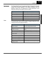
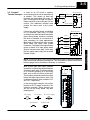
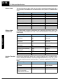
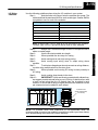
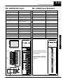
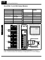
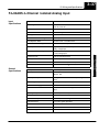
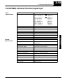
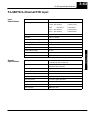
D4--64ND2, 24 VDC Input Module
CPU base only *
Base power required 5V 300 mA max
Inputs per module
64 (current sourcing)
External power required 24VDC ? 10%,
(optional)
320mA max
Commons per module
8 (isolated)
OFF to ON response
2.5 ms (typical)
Input voltage range
20 -- 28 VDC
ON to OFF response
5.0 ms (typical)
Peak voltage
30 VDC
Terminal type
ON voltage level
> 20 V
2, Removable
40 pin connectors
(sold separately)
OFF voltage level
< 13 V
Status indicators
Logic Side
Input impedance
4.8 K O
Weight
7.8 oz. (220 g)
Input current
5.0 mA @ 24 VDC
Minimum ON current
3.6 mA
Maximum OFF current
2.6 mA
Points
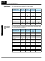
Derating Chart
32
0
0
32
10
20
30
40
50
50
68
86
104
122
Ambient Temperature (°C/°F)
60 °C
140°F
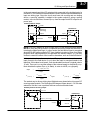
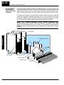
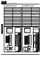
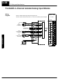
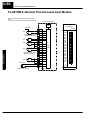
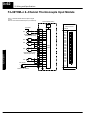
Wiring per 32pts.
with 24V on Connector
Wiring per 32pts.
using EXT 24VDC Connector
Internally
Connected
0v
-24VDC +
Current Flow
COM
Current Flow
-24VDC
0v
COM
+
Current Flow
Current Flow
0v
COM
+
24VDC --
Current Flow
COM
0v
INPUT
A/C
0
1
2
3
4
5
6
7
B/D
0
1
2
3
4
5
6
7
0
1
2
3
4
5
6
7
0
1
2
3
A4
A5
A6
A7
0V
A14
A15
A16
A17
0V
B4
B5
B6
B7
0V
B14
B15
B16
B17
0V
C0
C1
C2
C3
C5
C10
C11
C12
C13
C6
D0
D1
D2
D3
C7
D10
D11
D12
D13
C8
C4
C5
C6
C7
0V
C14
C15
C16
C17
0V
D4
D5
D6
D7
0V
D14
D15
D16
D17
0V
DISPLAY
SELECT
A-B
C-D
20--28VDC
4.2--5.8mA CLASS2
CN1
CN2
Input
Input
To LED
To LED
EXT
24VDC
Optical
Isolator
Common
Optical
Isolator
24VDC
-+
Common
0V
24VDC Ext
+
--
4
5
6
7
D4--64ND2
Connector Pins
A0
A1
A2
A3
C1
A10
A11
A12
A13
C2
B0
B1
B2
B3
C3
B10
B11
B12
B13
C4
Current Flow
Current Flow
24VDC
0V
+
+
--
--
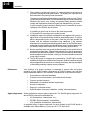
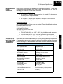
* Module location -- this module placement is
restricted to the local base on DL430/DL440
systems. It may also be placed in expansion
bases in DL450 systems that are using the new
(--1) bases.
+
--
I/O Wiring and
Specifications
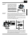
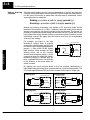
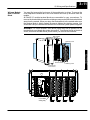
Since there are only 32 LEDs on the module, you
can only display the status for 32 points at one
time. In the A - B position the status of the first
group of 32 input points (A0--A17, B0--B17) are
displayed (connector 1). In the C - D position the
status of the second group of 32 input points
(C0--C17, D0--D17) are displayed (connector 2).
64
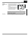
Getting Started
Module Location