1
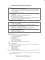
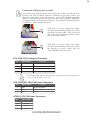
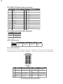
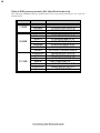
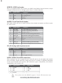
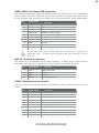
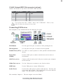
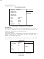
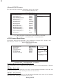
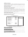
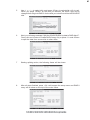
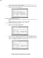
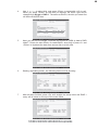
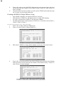
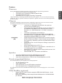
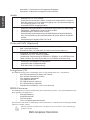
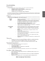
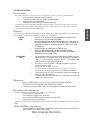
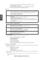
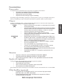
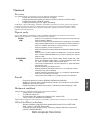
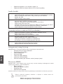
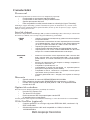
12
ATX_PWR: ATX 24-pin Power Connector
Pin
Signal Name
1
2
3
4
5
6
7
8
9
+3.3V
10
11
12
+12V
Pin
13
14
15
16
17
18
19
20
21
+3.3V
Ground
+5V
Ground
+5V
Ground
PWRGD
+5VSB
22
23
24
+12V
+3.3V
Signal Name
+3.3V
-12V
COM
PS_ON
COM
COM
COM
-5V
+5V
+5V
+5V
COM
SJ1: Single-color LED header (optional)
Pin
Signal Name
ACPI LED
Signal
Name
1
Pin
2
3
ACPI LED
5VSB
ACPI LED function
SJ1
S0
1
Light
S1
Blinking
S3
S4/S5
Blinking
Dark
Front Panel Header
The front panel header (PANEL1) provides a standard set of switch and LED headers
commonly found on ATX or Micro ATX cases. Refer to the table below for information:
Pin
Signal
Function
Pin
Signal
Function
1
HD_LED_P Hard disk LED(+)
2
FP PWR/SLP *MSG LED(+)
3
HD_LED_N Hard disk LED(-)
4
FP PWR/SLP *MSG LED(-)
5
RST_SW_N Reset Switch(-)
6
PWR_SW_P Power Switch(+)
7
9
RST_SW_P
RSVD
8
PWR_SW_N Power Switch(-)
Reset Switch(+)
Reserved
* MSG LED (dual color or single color)
10 Key
No pin
Installing the Motherboard