1
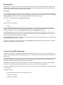
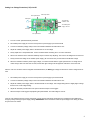
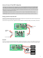
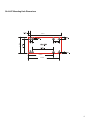
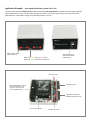
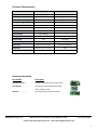
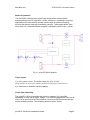
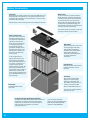
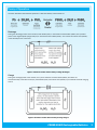
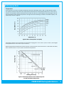
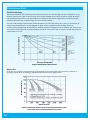
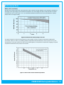
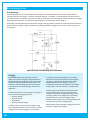
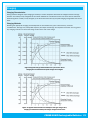
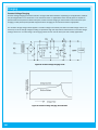
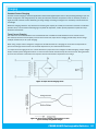
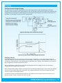
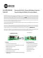
picoUPS-100-LVP
Advanced SLA UPS / Charger With Battery Protection
SLA-LVP
Deep Discharge SLA Battery Protection Module
Sealed lead acid (SLA), Lithium Ion (Li-Ion) Lithium Polymer (Li-Po) or LiFePO4 batteries, are permanently destroyed when
they are over discharged. The SLA-LVP module is designed around the ICL7665 voltage monitor ic and provides protection
against destructive deep discharge condition, through its constant monitoring of the SLA battery voltage. When the critical
discharge threshold voltage is approaching, the SLA-LVP module triggers an early warning alarm to indicate that corrective
action (such as battery recharging) is required. If corrective action is not taken, the SLA-LVP will then automatically cut off
the load as soon as the critical discharge voltage is reached.
The SLA-LVP will keep the load disconnected until the battery voltage is restored to an acceptable level, at which time it will
automatically reconnect the load.
The SLA-LVP is simply installed between the SLA battery and the load. It has been designed as an add-on battery protection circuit for use with the picoUPS-100 uninterruptible power supply / charger module from www.mini-box.com to provide
an advanced featured SLA uninterruptible battery backup power supply for a wide range of applications.
The SLA-LVP module when combined together with the picoUPS-100 results in a highly compact, advanced featured modulular solution for custom SLA battery based uninterruptible power power supply battery backup systems.
picoUPS-100-LVP module
(picoUPS-100 plus SLA-LVP)
Features
SLA-LVP module
Typical Applications
● SLA battery deep discharge protection
● SLA battery deep discharge protection
● Early warning discharge alarm: selectable Beeper or flashing LED
● Custom Uninterruptible power supplies
● MOSFET load switching up to 10A
● Portable battery powered systems
● Adjustable hysteresis
● Battery backup systems
● Adjustable Early Warning voltage trigger voltage
● Emergency power supplies
● Adjustable battery cutoff voltage
● Alarm systems
● Designed for the picoUPS-100 uninterruptible power supply / battery
charger module
1
Basic Operation
It is important to note that the SLA battery terminal voltage under load will be lower than the battery terminal voltage when the
load is removed. When the load is removed, the battery voltage rebounds to a higher voltage. The amount of voltage rebound
depends on the load current draw and the state of battery charge.
For example:
A 12V SLA battery supplying a load current of 5A can measure 11V under load after some time, but as soon as the load is removed, the battery voltage can rebound to 12.3V. This effect is taken into account when configuring the SLA-LVP module Early
Warning (E/W) threshold voltage and the Low Voltage Protection (LVP) load cut-off voltage.
The SLA-LVP modules are pre-configured E/W trigger voltage of:
● 11.7V
and a LVP load cut-off voltage of:
● 11.5V
With the above E/W and LVP settings, when the battery voltage drops to 11.7V the E/W is triggered and the module starts
beeping its alarm (or flashes its LED depending on the jumper setting) to signal that battery recharging is required. When the
external power supply is connected to the picoUPS-100-LVP, then the beeping E/W alarm will stop.
If the charging power supply is not connected to the module, the battery voltage continues to drop. Once it reaches the 11.5V
LVP threshold setting, the picoUPS-100-LVP automatically disconnects the load and ends the E/W alarm and is locked in protection mode, preventing further discharge to the battery.
The picoUPS-100-LVP recovers out of protection mode as soon as the 16V external charging power supply is connected to the
picoUPS-100-LVP and the battery is recharged.
The SLA-LVP module may be user reconfigured for alternative E/W and LVP voltage thresholds, via the relevant on-board potentiometers as described in configuration below.
Custom LVP and E/W Configuration
The SLA-LVP module is pre-configured with its E/W and LVP threshold voltages at 11.7V and 11.5 V respectively. With these
settings, the E/W will trigger when the battery voltage drops to 11.7 V and the LVP load cut-off will occur when the battery voltage is at 11.5V.
The LVP hysteresis is set to 1.5V to allow for battery voltage rebound condition when the load is cut-off. Without the hysteresis
allowance, undesired load switching oscillation will occur. From tests, it has been determined that the 1.5V hysteresis is just
greater than the rebound voltage which is desired to prevent oscillation.
Fixed resistors R1 (180K) and R4 (10K) set the hysteresis for LVP and E/W respectively. R1 is the most critical in oscillation
prevention. To increase the hysteresis, a higher value will be used or a lower value for reduced hysteresis.
The “LV set” potentiometer is used to set the LVP cut-off voltage. To change the LVP and E/W voltages, proceed with the steps
on the next page.
Equipment required:
● Variable DC power supply with an output voltage up to 16V
● Voltmeter or multimeter
● Small flat tip screwdriver
2
Setting Low Voltage Protection (LVP) Cut-Off
E/W Hysteresis R4
E/W output select
E/W adjust
To multimeter /
voltmeter / load
To variable power
supply. 16V max.
LVP adjust
LVP Hysteresis R1
E/W outputs
1.
Turn the “LV Set” potentiometer fully clockwise
2.
Set variable power supply to 15V and connect power to power supply input screw terminal
3.
Connect a multimeter (Voltage scale) to the Vout terminals. Multimeter should measure 15V.
4.
Adjust the variable power supply down to the desired LVP cut-off voltage
5.
Slowly adjust the LV Set potentiometer counter clockwise whilst monitoring the V out on the multimeter
6.
When Vout measured on the multmeter suddenly drops to read 0V stop adjusting. The LVP cut-off voltage has now been set .
7.
Slowly increase the voltage on the variable power supply. (Do not exceed 15V). And monitor the multimeter voltage
8.
When the mutimeter reads the power supply voltage, Vout has turned ON and the upper hysteresis turn-on voltage can be
noted. Always, after LVP cutoff has occurred, at least this upper voltage must be applied to restore the Vout to the load.
After the “LVP set” has been custom configured as described above, the E/W trigger voltage can be then be custom configured as follows:
1.
Set variable power supply to 15V and connect power to power supply input screw terminal.
2.
Connect a multimeter (Voltage scale) to the Vout terminals. Multimeter should measure 15V.
3.
Adjust the variable power supply down to the desired E/W cut-off voltage. This voltage setting will be a slightly higher voltage
than the LVP cut-off voltage setting.
4.
Adjust the “E/W Set” potentiometer to the point at which the beeper / LED triggers.
5.
When the beeper / LED triggers stop adjusting the potentiometer. The E/W voltage is now set .
Once the LVP and E/W has been custom configured, connect the load and test the performance by simulating the SLA battery discharge by slowly reducing the power supply voltage. IMPORTANT: Never exceed the maximum input voltage of 16V. Doing so will destroy the SLA-LVP module.
3
Advanced Custom LVP and E/W Configuration
This sidebar is for Advanced Custom Configuration Only for special applications that require LVP and E/W settings
that are beyond the adjustable range capabilities determined by the existing SLA-LVP on-board component values.
Refer to the ICL7665 data sheet formula fig. 5 on page 8 for calculating custom hysteresis values. Cross reference data sheet
designations to module designations as follows:
For LVP values: (R21-data sheet =Vset+R2 on module, R31=R1 on module, R11-data sheet=R3=150K on module)
For E/W values: (R22-data sheet=E/W+R5 on module, R32-data sheet=R4 on module, R12-data sheet=R6 on module)
Pairing picoUPS-100 with SLA-LVP
The SLA-LVP module has eight mounting holes. The four inner holes align with the the picoUPS-100 for stand-off mounting the two assemblies together into one compact device as shown on page 1.
The interconnect wiring is shown below, together with connection details to an external power supply, 12V SLA battery, and the load
Vout to load
Vin 16VDC max.
To external
16VDC power
supply
Vout
to 12V SLA battery
SLA-LVP
The SLA-LVP module may be used without the picoUPS-100 module, as shown below. In this case, the SLA battery and the SLA-LVP
module need an isolation circuit such as a switch or relay when the external charger power supply is connected to charge the battery.
Load
SLA Battery
Charger PSU
4
SLA-LVP Mounting Hole Dimensions
1.51 in.
3.11 in.
2.41 in.
2.94 in.
5
Application Example:
Rechargeable SLA Battery Power Pack / UPS
This power pack uses the picoUPS-100-LVP modules and includes a DC-DC Buck/Boost regulator to provide multiple selectable
output voltages from 5V to 24V. The SLA battery management is taken care of by the picoUPS-100-LVP which provides power
status indication, 3 stage battery charging, deep discharge protection and more.
External 16VDC Power
Supply /Charger In
Status LED: Amber - Charging. Red - Battery
Backup ON. Green - External Power Supply ON
Select DC voltage output and slected output
voltage display
SLA-LVP module
SLA battery output
Buck / Boost DC-DC Converter
provides slectable 5V, 12V,
15V, 16V, 18V, 19V 20V or
24VDC regulated output
Regulated DC output from
Buck/Boost DC-DC Converter
12V, 4.5Ah SLA Battery
PicoUPS-100 module
6
Technical Characteristics
Parameters
Characteristics
Comments
E/W Trigger Voltage
11.7V
Adjustable
LVP load cut-off voltage
11.5V
Adjustable
Max Input Voltage
16V
Max Load Current
5A
No Load Current
0.2mA
Vin=12V
E/W output
Beeper / LED
Jumper selectable
Output Voltage
=Input Voltage
LVP Hysteresis
1.5V
Output enable
13V
Reverse Polarity Protection
Vin voltage
None
Dimensions
1.5in. X 3.1 in. X 0.5 in.
SLA-LVP module only
Dimensions
1.5in. X 3.1 in. X 1.35 in.
PicoUPS-100-LVP with 0.4” standoffs
Ordering Information
Part Number
Description
picoUPS-100-LVP…….
picoUPS-100 module plus SLA-LVP module
picoUPS-100..…………
picoUPS-100 uninterruptible power supply
battery charger module
SLA-LVP……………..…
ABACOM Technologies, Inc.
SLA deep discharge protection module
32 Blair Athol Crescent, Etobicoke, Ontario, M9A 1X5, Canada
website: http://www.abacom-tech.com
Tel:+1(416) 236 3858
email: [email protected]
7
The following pages contain the user manual for
the picoUPS-100 module
8
picoUPS-100
12V DC battery backup system
Micro UPS (uninterruptible power supply)
Quick Installation Guide
Version 1.0b
P/N picoUPS-100
Introduction
The picoUPS-100 is a small yet powerful UPS (uninterruptible power supply)
solution. The picoUPS-100 was conveniently design to be compatible with
quarter brick PSU standard (58 x 36mm).
The picoPSU-100 ensures uninterrupted power for your electronics by
automatically switching in between a DC input source (15-18V) and a Lead
Acid (SLA battery). The switching in between the power sources is
instantaneous, thus allowing smooth, uninterrupted device operation. The
picoUPS-100 also has a built-in, two stage battery charger unit.
Mini-Box.com
ATX DC-DC Converter Series
Mode of Operation
The PICOUPS-100 has been specifically designed for uninterruptible
small/medium power PC operation, where “always on” operating is required.
Applications for the picoUPS include a wide range of systems including
servers and telecom and high availability systems. These applications often
have either N+1 redundant power supplies, redundant power buses, or both.
Fig 1.1 picoUPS block diagram
Power inputs
1) A 16V power source. The actual range for V(in) 15-18V.
NOTE: Unit will work as low as 6V, but battery will not be charged if V(in) is lower than 15V!
2) A Lead Acid or Sealed Lead Acid battery
Power Path Switching
The picoUPS-100 will automatically switch in between V(In) and Batt
depending on who has a higher voltage. The switching hysteresis is as low as
10mv. As a result, when AC/DC power is lost, the picoUPS will automatically
switch to Battery output. The switching speed is about 100nS.
picoUPS-100 Quick Installation Guide
Page 2
Mini-Box.com
ATX DC-DC Converter Series
Battery charging, bulk charging mode
The picoUPS-100 has a built in, two stage SLA battery charger. First stage is
bulk charging stage, where the battery is being charged at a constant
current of ~500mA. Depending on battery size and level of discharge, bulk
charing stage can be anywhere from few minutes to few hours. For example,
a typical 7AH / 12V SLA battery will fully change in 6-12 hours. During this
time the Orange LED will be ON.
Battery charging, float charging mode
When the battery is near full capacity, charge current will slowly decrease. At
this point, picoUPS will switch charging mode from bulk to float charge. Float
charging ensures that the battery is kept at a precise 13.5V.
Typical configuration
A typical configuration for a low / medium power computer setup is comprised
from a 12V / 7Ah battery, a 16V / 5A AC/DC adapter. The output can be
coupled to ATX power supply such as M1-ATX, M2-ATX, M3-ATX or
picoPSU-60-WI or picoPSU-120-25.
Specifications, picoUPS-100.
Power Ratings (max load = 10A)
Volts (V)
6-18V*
Max Load (A)
6A fanless / 10A fan
Peak Load (A)
12A
Bulk Charge
500mA
* if Vcc is below 15V unit will work but will not fully charge the Battery.
Precautions for operating this DC-DC converter:
-Inrush input current should not exceed 20A.
-Peak load should not exceed 60 seconds.
-Low voltage battery cut-off not provided by this module.
-Float voltage is 13.5V (+/- 1%), use only with SLA batteries
Green LED: V(in) is active. V(in) is routed to V(out).
Red LED: Batt is active. Batt is routed to V(Out).
Orange LED: Batt is in bulk charging mode.
Input Requirements: 16V regulated, min=2A, max = load dependent.
picoUPS-100 Quick Installation Guide
Page 3
Mini-Box.com
ATX DC-DC Converter Series
Size: 58mm(L) * 36mm(W) * 20mm (H) (1U compliant)
Weight: 30gramms
Connectors: Faston Blades, 0.187’
LED: 0603 status LEDs (Vcc, BATT, Charge)
Overload protection
This unit does not provide overload protection. Inrush current should not
exceed more than 20A for 1 second.
Operating environment
Temperature: -20 to 65 degree centigrade.
NOTE: For fanless operation, please ensure that the PSU body temperature,
T(psu) does not exceed 75C. Higher temperatures are allowed, but MTBF
could decrease. Maximum power supply body temperature T(psu) is 85C.
Relative Humidity: 10 to 90 percent, non-condensing.
Efficiency, MTBF: 95%. MTBF=100K hours at T(psu) 55Celsius.
Shipping and storage
Temperature -40 to +40 degree centigrade. Relative humidity 5 to 90 percent,
non-condensing
Warranty
1 Year Limited Warranty statement. Warranty is void if maintenance or
calibration is performed by end-user or by use in conjunction with power
modules not provided by mini-box.com.
Support
Web Site: http://www.mini-box.com/site/support.html
picoUPS-100 Quick Installation Guide
Page 4
Table of Contents
Features of Power-Sonic Sealed Lead Acid Batteries.................................................. 1
Battery Construction.........................................................................................................2
Theory of Operation...................................................................................................3 & 4
Battery Capacity.........................................................................................................5 & 6
Battery Capacity Selector.................................................................................................7
Performance Data.............................................................................................................8
Discharge...................................................................................................................................8
Open Circuit Voltage..................................................................................................................8
Temperature..............................................................................................................................9
Shelf Life and Storage............................................................................................................10
Battery Life........................................................................................................................ 10-11
Over Discharge........................................................................................................................12
Charging............................................................................................................................12
Charging Techniques Summary.............................................................................................13
Charging Characteristics........................................................................................................13
Charging Methods...................................................................................................................13
Constant Voltage Charging.....................................................................................................14
Constant Current Charging.....................................................................................................15
Taper-Current Charging...........................................................................................................15
Overcharging...........................................................................................................................16
Undercharging.........................................................................................................................16
Charging for Cycle Operation..................................................................................................16
Charging for Standby Operation.............................................................................................16
Two-Step Constant Voltage Charging.....................................................................................17
Charging in Series...................................................................................................................17
Charging in Parallel.................................................................................................................18
Temperature Compensation...................................................................................................18
Top Charging............................................................................................................................18
Charging Efficiency..................................................................................................................19
Important Do’s and Don’ts.............................................................................................20
Handling...................................................................................................................................20
Installation...............................................................................................................................20
Charging...................................................................................................................................21
Notes.................................................................................................................................22
Glossary............................................................................................................................24
Features of Power-Sonic Sealed Lead Acid Batteries
Sealed/Maintenance–Free
The valve regulated spill proof construction allows
trouble-free safe operation in any position. There is no
need to add electrolyte, as gases generated during the
charge phase are recombined in a unique “oxygen cycle”.
Power-Sonic sealed lead acid batteries can be operated
in virtually any orientation without the loss of capacity or
electrolyte leakage. However, upside down operation is
not recommended.
Long Shelf Life
Compact
Power-Sonic batteries utilize state of the art design, high
grade materials, and a carefully controlled plate-making
process to provide excellent output per cell. The high
energy density results in superior power/volume and
power/weight ratios.
Low Pressure Valve Regulators
All batteries feature a series of low pressure one-way
relief valves. These valves safely release any excessive
accumulation of gas inside the battery and then reseal.
A low self-discharge rate, up to approximately 3% per
month, may allow storage of fully charged batteries
for up to a year, depending on storage temperatures,
before charging becomes critical. However, we strongly
recommend that all batteries should be recharged within
six months of receipt as it will enhance their long term life.
High Discharge Rate
Please refer to this Technical Manual and individual
battery specification sheets for more details.
Power-Sonic batteries may be discharged over a
temperature range of -40°C to +60°C (-40°F to +
140°F) and charged at temperatures ranging from
-20°C to +50°C (-4°F to +122°F).
Design Flexibility
Same model batteries may be used in series and/or
parallel to obtain choice of voltage and capacity. The
same battery may be used in either cyclic or standby
applications. Over 80 models available to choose from.
Deep Discharge Recovery
Special separators, advanced plate composition and a
carefully balanced electrolyte system ensure that the
battery has the ability to recover from excessively deep
discharge.
Economical
The high watt-hour per dollar value is made possible by
the materials used in a sealed lead-acid battery; they are
readily available and low in cost.
Easy Handling
No special handling precautions or shipping containers,
surface or air, are required due to the leak-proof
construction. Please refer to the declaration of non
restricted status for D.O.T. and I.A.T.A. as listed in the
Literature section of our website: www.power-sonic.com.
Low internal resistance allows discharge currents of up
to ten times the rated capacity of the battery. Relatively
small batteries may thus be specified in applications
requiring high peak currents.
Wide Operating Temperature Range
Rugged Construction
The high impact resistant battery case is made of nonconductive ABS plastic. The case materials impart great
resistance to shock, vibration, chemicals and heat.
Flame Retardant (FR) battery cases and lids are available
where the end application dictates.
Long Service Life
PS/PSH and PSG Series: Have a design life of up to five
years in standby applications. In cyclical applications
up to 1,000 charge/discharge cycles can be expected
depending on average depth of discharge.
PG Series: Have a design life of up to 10 years in float
applications.
Please consult this Technical Manual and product
specifications to become aware of the many factors that
effect product life.
The information contained within is provided as a service to our customers and is for their information only. The
information and recommendations set forth herein are made in good faith and are believed to be accurate at the date
compiled. Power-Sonic Corporation makes no warranty expressed or implied.
POWER-SONIC Rechargeable Batteries
Battery Construction
Terminals
Depending on the model, batteries come either with AMP Faston type
terminals made of tin plated brass, post type terminals of the same
composition with threaded nut and bolt hardware, or heavy duty flag
terminals made of lead alloy.
A special epoxy is used as sealing material surrounding the terminals.
Relief valve
In case of excessive gas pressure build-up
inside the battery, the relief valve will open
and relieve the pressure. The one-way valve
not only ensures that no air gets into the
battery where the oxygen would react with
the plates causing internal discharge, but
also represents an important safety device in
the event of excessive overcharge.
Vent release pressure is between 2-6 psi; the
seal ring material is neoprene rubber.
Plates (electrodes)
Power-Sonic utilizes the latest
technology and equipment to
cast grids from a lead-calcium
alloy free of antimony. The
small amount of calcium and
tin in the grid alloy imparts
strength to the plate and
guarantees durability even in
extensive cycle service. Lead
dioxide paste is added to the
grid to form the electrically
active material.
In the charged state, the
negative plate paste is pure
lead and that of the positive
lead dioxide. Both of these are
in a porous or spongy form to
optimize surface area and
thereby maximize capacity. The
heavy duty lead calcium alloy
grids provide an extra margin of
performance and life in both
cyclic and float applications and
give unparalleled recovery from
deep discharge.
Electrolyte
Immobilized dilute sulfuric
acid: H2S04.
Separators
Power-Sonic separators are made
of non-woven glass fiber cloth
with high heat and oxidation
resistance. The material further
offers superior electrolyte
absorption and retaining ability,
as well as excellent ion
conductivity.
Case Sealing
Depending on the model the case
sealing is ultrasonic, epoxy or
heat seal.
Container
Case and lid material is ABS,
high impact, resin with high
resistance to chemicals and
flammability. Case and cover are
made of non-conductive ABS
plastic to UL94-HB or UL94 V-O.
This case has molded-in dividers
for each 2 volt cell.
Leakproof Design & Operational Safety
The leak proof construction of Power-Sonic batteries has
ensured that our batteries have been approved for
shipment by air, both by D.O.T. and I.A.T.A. Copies of
these approvals are available on our website:
www.power-sonic.com.
U.L’s component recognition
program for emergency lighting and
power batteries lists Power-Sonic
under file number MH20845
Theory of Operation
The basic electrochemical reaction equation in a lead acid battery can be written as:
Discharge
During the discharge portion of the reaction, lead dioxide (PbO2) is converted into lead sulfate (PbSO4) at the positive
plate. At the negative plate sponge lead (Pb) is converted to lead sulfate (PbSO4). This causes the sulfuric acid (2H2SO4)
in the electrolyte to be consumed.
Figure 1: Chemical reaction when a battery is being discharged
Charge
During the recharge phase of the reaction, the cycle is reversed. The lead sulfate (PbSO4) and water are
electrochemically converted to lead (Pb), lead dioxide (PbO4) and sulfuric acid (2H2SO4) by an external electrical charging
source.
Figure 2: Chemical reaction when a battery is being charged
POWER-SONIC Rechargeable Batteries
Theory of Operation
Oxygen Recombination
To produce a truly maintenance-free battery, it is necessary that gases generated during overcharge are recombined in
a so-called “oxygen cycle”. Should oxygen and hydrogen escape, a gradual drying out would occur, eventually affecting
capacity and battery life.
During charge, oxygen is generated at the positive and reacts with and partially discharges the sponge lead of the
negative. As charging continues the oxygen recombines with the hydrogen being generated by the negative, forming
water. The water content of the electrolyte thus remains unchanged unless the charging rate is too high.
In case of rapid generation of oxygen exceeding the absorbing capacity of the negative plate, the pressure relief valve
will open to release excessive gas.
Deep Discharge
Power-Sonic batteries are protected against cell shorting by the addition of a buffering agent that ensures the presence
of acid ions even in a fully discharged state.
Power-Sonic defines “deep discharge” as one that allows the battery voltage under load to go below the cut-off (or
“final”) voltage of a full discharge. The recommended cutoff voltage varies with the discharge rate. Table 1 shows the
final discharge voltages per cell.
It is important to note that deep discharging a battery at high rates for short periods is not nearly as severe as
discharging a battery at low rates for long periods of time. To clarify, let’s analyze two examples:
• Battery A – Discharged at the 1C rate to zero volts. “C” for a 4 AH battery, for example, is 4 amps. Full discharge is reached after about 30 minutes when
the battery voltage drops to 1.5V/cell. At this point, only 50% of rated capacity has been discharged (1
C amps x 0.5 hrs = 0.5C Amp. Hrs). Continuing the discharge to zero volts will bring the total amount of
discharged ampere-hours to approximately 75% because the rapidly declining voltage quickly reduces
current flow to a trickle. The battery will recover easily from this type of deep discharge.
• Battery B – Discharged at the 0.01 C rate to zero volts. 0.0IC for a 4 AH battery is 40mA. Full discharge is reached after 100+ hours when the terminal voltage
drops to 1.75 V/cell. At this point, the battery has already delivered 100% of its rated capacity (0.01 x
100 hrs = 1C Amp. Hrs.). Continuing the discharge to zero volts will keep the battery under load for a
further period of time, squeezing out every bit of stored energy. This type of “deep” discharge is severe and is likely to damage the battery. The sooner a severely
discharged battery is recharged, the better its chances to fully recover.
Discharge Current
Final Discharge Voltage Per Cell
0.1C or below, or intermittent discharge
1.75
0.17C or current close to it
1.75
0.6C or current close to it
1.70
From 1C to 2C or current close to it
1.50
3C or current close to it and above
1.37
Table 1: Final discharge voltage per cell
Capacity
The capacity of a battery is the total amount of electrical energy available from a fully charged cell or cells. Its value
depends on the discharge current, the temperature during discharge, the final (cut-off) voltage and the general history
of the battery.
Table 2 shows capacities for various multiples of the 20-hour discharge current for PS, PSH and PSG models.
20 Hour Rate
10 Hour Rate
Rated
Capacity
Amps
AH
0.5 AH
0.025
0.50
0.8 AH
0.04
0.80
1.1 AH
0.055
1.10
1.4 AH
0.07
1.40
2.0 AH
0.10
2.3 AH
0.115
5 Hour Rate
AH
Amps
0.045
0.45
0.072
0.72
0.10
0.13
2.00
1 Hour Rate
AH
Amps
AH
0.08
0.40
0.30
0.30
0.13
0.65
0.48
0.48
1.00
0.19
0.95
0.68
0.68
1.30
0.24
1.20
0.85
0.85
0.19
1.90
0.34
1.70
1.24
1.24
2.30
0.225
2.25
0.39
1.95
1.38
1.38
0.125
2.50
0.22
2.20
0.40
2.00
1.50
1.50
2.8 AH
0.14
2.80
0.25
2.50
0.48
2.40
1.70
1.70
2.9 AH
0.145
2.90
0.26
2.60
0.49
2.45
1.80
1.80
3.2 AH
0.16
3.20
0.30
3.00
0.54
2.70
2.00
2.00
3.4 AH
0.17
3.40
0.33
3.30
0.58
2.90
2.20
2.20
3.5 AH
0.175
3.50
0.33
3.40
0.59
2.95
2.17
2.17
3.8 AH
0.19
3.80
0.35
3.50
0.64
3.20
2.40
2.40
4.5 AH
0.225
4.50
0.41
4.10
0.64
3.20
2.75
2.75
5.0 AH
0.25
5.00
0.43
4.30
0.80
4.00
3.00
3.00
5.00
0.90
4.50
3.60
3.60
2.5 AH
Amps
5.4 AH
0.27
5.40
0.50
5.5 AH
0.275
5.50
0.54
5.40
0.95
4.75
3.70
3.70
6.0 AH
0.30
6.00
0.56
5.60
0.98
4.90
3.60
3.60
6.5 AH
0.325
6.50
0.61
6.10
1.10
5.50
4.03
4.03
7.0 AH
0.35
7.00
0.63
6.30
1.19
5.95
4.34
4.34
0.36
7.20
0.70
7.00
1.30
6.50
4.60
4.60
8.0 AH
0.40
8.00
0.78
7.75
1.40
7.00
4.80
4.80
8.5 AH
0.425
8.50
0.81
8.10
1.50
7.50
6.50
6.50
9.0 AH
0.45
9.00
0.83
8.30
1.54
7.70
5.60
5.60
9.30
1.70
8.50
6.20
6.20
7.2 AH
10.0 AH
0.50
10.00
0.93
10.5 AH
0.53
10.50
0.98
9.80
1.87
9.35
6.82
6.82
12.0 AH
0.60
12.00
1.15
11.50
2.10
10.50
7.30
7.30
13.0 AH
0.65
13.00
1.22
12.20
2.30
11.50
8.00
8.00
14.0 AH
0.70
14.00
1.30
13.00
2.50
12.50
8.45
8.45
17.00
3.20
16.00
11.10
11.10
18.0 AH
0.90
18.00
1.70
20.0 AH
1.00
20.00
1.85
18.50
3.40
17.00
12.40
12.40
21.0 AH
1.05
21.00
2.00
20.00
3.70
18.50
13.00
13.00
26.0 AH
1.30
26.00
2.40
24.00
4.40
22.00
16.10
16.10
26.20
5.00
25.00
18.60
18.60
28.0 AH
1.40
28.00
2.62
35.0 AH
1.75
35.00
3.30
33.00
6.20
31.00
25.00
25.00
36.0 AH
1.80
36.00
3.35
33.50
6.12
30.60
22.30
22.30
40.0 AH
2.00
40.00
3.80
38.00
6.70
33.50
24.00
24.00
55.0 AH
2.75
55.00
5.10
51.00
8.80
44.00
30.60
30.60
7.20
72.00
13.60
68.00
47.00
47.00
75.0 AH
3.75
75.00
100.0 AH
5.00
100.00
9.20
92.00
15.80
79.00
55.20
55.20
110.0 AH
5.50
110.00
10.30
103.00
17.70
88.50
61.80
61.80
140.0 AH
7.00
140.00
13.50
135.00
24.00
120.00
84.00
84.00
210.00
20.00
200.00
36.00
180.00
168.00
168.00
210.0 AH
10.50
Table 2: Capacities for various multiples of the 20-hour discharge current - PS, PSH and PSG models.
POWER-SONIC Rechargeable Batteries
Capacity
Table 3 shows capacities for various multiples of the 20-hour discharge current for PG models.
Rated
Capacity
20 Hour Rate
10 Hour Rate
5 Hour Rate
1 Hour Rate
Amps
AH
Amps
AH
Amps
AH
Amps
AH
28.0 AH
1.50
30.00
2.80
28.00
5.10
25.50
18.60
18.60
35.0 AH
1.80
36.00
3.50
35.00
6.50
32.50
27.00
27.00
42.0 AH
2.25
45.00
4.20
42.00
7.20
36.00
25.20
25.20
56.0 AH
3.00
60.00
5.60
56.00
9.50
47.50
33.00
33.00
65.0 AH
3.53
70.60
6.50
65.00
11.20
56.00
39.00
39.00
75.0 AH
4.00
80.00
7.50
75.00
12.90
64.50
45.00
45.00
92.0 AH
4.90
98.00
9.20
92.00
15.80
79.00
55.20
55.20
103.0 AH
5.55
111.00
10.30
103.00
17.70
88.50
61.80
61.80
124.0 AH
6.45
129.00
12.40
124.00
21.30
106.50
74.40
74.40
144.0 AH
7.70
154.00
14.40
144.00
24.08
120.40
84.00
84.00
153.0 AH
8.30
166.00
15.30
153.00
26.30
131.50
91.80
91.80
210 0 AH
11.30
226.00
21.00
210.00
36.10
180.50
126.00
126.00
Table 3: PG-Series batteries, by industry convention, are rated at their 10 hour rate.
Capacity, expressed in ampere-hours (AH), is the
product of the current discharged and the length of
discharge time. The rated capacity (C) of a PowerSonic battery (PS, PSH and PSG-Series) is measured
by its performance over 20 hours of constant current
discharge at a temperature of 20°C (68°F) to a cut
off voltage of 1.75 volts/cell.
By cycling the battery a few times or float charging
it for a month or two, the highest level of capacity
development is achieved. Power-Sonic batteries
are fully charged before leaving the factory, but full
capacity is realized only after the battery has been
cycled a few times or been on float charge for some
time.
As an example, model PS-610, with a rated capacity of
1.1 AH will deliver 55mA (1/20 of 1.1 AH, or 0.05C) for
20 hours before the voltage reaches an end voltage of
5.25 volts.
When a battery discharges at a constant rate, its
capacity changes according to the amperage load.
Capacity increases when the discharge current is less
than the 20 hour rate and decreases when the current
is higher.
POWER-SONIC Rechargeable Batteries
Proper battery selection for a specific application can be made from
this graph if the required time and current are known. For example,
to determine the proper capacity of a battery providing 3 amps for 20
minutes, locate the intersection of these values on the graph. The line
immediately above that point represents the battery which will meet
the requirement.
Figure 3: Capacity lines for Power-Sonic batteries
Discharge Time (Amps)
Figure 3 shows capacity lines for major Power-Sonic battery models
with different ampere-hour ratings. Amperage is on the horizontal
scale and the time elapsed is on the vertical scale; the product of
these values is the capacity.
Discharge Time (hrs)
Performance Data
Discharge
During discharge the voltage will decrease. The graphs in Figure 4 illustrate this for different discharge rates and
ambient temperatures. “C” is the rated capacity of a battery: “C” for model PS-61O (6V – 1.1 AH) is 1.1AH. By
convention the rating of nearly all sealed-lead acid batteries, is based on a 20-hour (0.05C) discharge rate. For larger
batteries used for telecom and large UPS systems (our PG-Series) the convention is to use a 10-hour rate (0.1C).
Terminal Voltage
An important feature of Power-Sonic batteries is shown in the discharge curves; namely, the voltage tends to remain
high and almost constant for a relatively long period before declining to an end voltage.
Discharge Time
Figure 4: Discharge Characteristic Curves at 20°C (68°F)
Open-Circuit Voltage
Open circuit voltage varies according to ambient temperature and the remaining capacity of the battery. Generally, open
circuit voltage is determined by the specific gravity of the electrolyte. Discharging a battery lowers the specific gravity.
The open circuit voltage of a Power-Sonic battery is 2.16 V/cell when fully charged and 1.94 V/cell when completely
discharged.
Terminal Voltage
As seen in Figure 4, under load, the battery can deliver useful energy at less than 1.94 V/cell, but after the load is
removed the open circuit voltage will “bounce back” to voltages shown in Figure 5, dependent upon residual capacity.
Residual Capacity (%)
Figure 5: Open-Circuit Voltage Characteristics
Performance Data
Temperature
Capacity Ratio (%)
Actual capacity is a function of ambient temperature and rate of discharge. At 20°C (68°F) rated capacity is 100%.
The capacity increases slowly above this temperature and decreases as the temperature falls. Even at -40ºC (-40°F),
however, the Power-Sonic battery will still function at better than 30% of its rated capacity when discharged at the 20hour rate (0.05C). At any ambient temperature, the higher the rate of discharge, the lower the available capacity. This
relationship is shown in Figure 6.
Temperature (°C)
Figure 6: Effect of Temperature on Capacity
Power-Sonic batteries may be discharged at temperatures ranging from -40°C to 60°C (-40°F to 140°F) and charged
at temperatures from -20°C to 50°C (-4°F to 122°F).
Discharge Time
While raising ambient temperature increases capacity, it also decreases useful service life. It is estimated that battery
life is halved for each 10°C (18°F) above normal room temperature.
Discharge Current (A)
Figure 7: Relationship between current and discharge time
for different ambient temperatures
POWER-SONIC Rechargeable Batteries
Performance Data
Shelf Life & Storage
Low internal resistance and special alloys in the electrodes assure a low self discharge rate and, consequently, a long
shelf life. If kept at 20°C (68°F), about 60-70% of the nominal capacity remains after one year of storage. Due to the
self-discharge characteristics of this type of battery, it is imperative that they be charged within 6 months of storage,
otherwise permanent loss of capacity might occur as a result of sulfation.
Capacity Retention Ratio(%)
The rate of self discharge varies with the ambient temperature. At room temperature (20°C (68°F)) it is about 3% per
month. At low temperatures it is nearly negligible; at higher ambient temperatures self discharge increases.
To obtain maximum battery life and performance, batteries should be recharged as soon as possible after each use and
not stored in a discharged state. If possible batteries should be stored at 20°C (68°F) or lower, and recharged every six
months when not in use.
Storage Period (Months)
Figure 8: Self Discharge Characteristics
Battery Life
Retention Capacity (%)
Cyclic Use: The number of charge/discharge cycles depends on the capacity taken from the battery (a function of
discharge rate and depth of discharge), operating temperature and the charging method.
Number of Cycles
Figure 9: Relationship between depth of discharge and number of cycles
as well as increases of capacity during the early cycles.
10
Performance Data
Battery Life (continued)
Retention Capacity (%)
Standby Use: The float service life, or life expectancy under continuous charge, depends on the frequency and depth of
discharge, the charge voltage, and the ambient temperature. At a float voltage of 2.25V to 2.30V/cell and an ambient
temperature of 20°C to 25°C (60°F to 77°F) Power-Sonic batteries should last four to five years before the capacity
drops to 60% of its original rating.
Years
Figure 10: Indicates how capacity changes over time.
Service Life (Years)
The graph in Figure 11 shows life characteristics in float (standby) service for ambient temperatures ranging from 15°C to 55°C (60°F to 130°F). If prevailing ambient temperatures are well above 20°C to 25°C (68°F to 77°F) the
life expectancy of this type of battery in float service depends greatly on temperature compensated charging. The typical
temperature coefficient is 2mV/cell/20°C and under.
Temperature (°C)
Figure 11: Service life at various ambient temperatures
POWER-SONIC Rechargeable Batteries 11
Performance Data
Over Discharge
To optimize battery life, it is recommended that the battery be disconnected from the load (either electronically or
manually) when the end voltage - a function of the discharge rate - is reached. It is the voltage point at which 100% of
the usable capacity of the battery has been consumed or continuation of the discharge is useless because of the voltage
dropping below useful levels. The final discharge voltages per cell are shown in Table 1 (Page 4). Discharging a sealed lead-acid battery below this voltage or leaving a battery connected to a load will impair the battery’s
ability to accept a charge. To prevent potential over discharge problems, voltage cut off circuits as shown in Figure 12
may be used.
Figure 12: Circuits of Over-Discharge Preventative Device
Charging
Dependable performance and long service life
depend upon correct charging. Faulty procedures or
inadequate charging equipment result in decreased
battery life and/or unsatisfactory performance. The
selection of suitable charging circuits and methods
is as important as choosing the right battery for the
application.
Power-Sonic batteries may be charged by using any of
the conventional charging techniques:
• Constant Voltage
• Constant Current
• Taper-Current
• Two Step Constant Voltage
To obtain maximum service life and capacity, along
with acceptable recharge time and economy, constant
voltage-current limited charging is recommended.
12
To charge a Power-Sonic SLA battery, a DC voltage
between 2.30 volts per cell (float) and 2.45 volts per
cell (fast) is applied to the terminals of the battery.
Depending on the state of charge, the cell may
temporarily be lower after discharge than the applied
voltage. After some time, however, it should level off.
During charge, the lead sulfate of the positive plate
becomes lead dioxide. As the battery reaches full
charge, the positive plate begins generating dioxide
causing a sudden rise in voltage due to decreasing
internal resistance. A constant voltage charge,
therefore, allows detection of this voltage increase and
thus control of the current charge amount.
Additional information regarding charging methods can
be found on pages 13 through 19.
Charging
Charging Characteristics
During constant voltage or taper charging, the battery’s current acceptance decreases as voltage and state of charge
increase. The battery is fully charged once the current stabilizes at a low level for a few hours. There are two criteria for
determining when a battery is fully charged: (1) the final current level and (2) the peak charging voltage while this current
flows.
Charging Methods
Selecting the appropriate charging method depends on the intended use (cyclic or float service), economic
considerations, recharge time, anticipated frequency and depth of discharge, and expected service life. The key goal of
any charging method is to control the charge current at the end of the charge.
Figure 13: Typical charge characteristics for cycle service where
charging is non-continuous and peak voltage can be higher.
Figure 14: Typical characteristics for standby service type charge. Here,
charging is continuous and the peak charge voltage must be lower.
POWER-SONIC Rechargeable Batteries 13
Charging
Constant Voltage Charging
Constant voltage charging is the best method to charge Power-Sonic batteries. Depending on the application, batteries
may be charged either on a continuous or non-continuous basis. In applications where standby power is required to
operate when the AC power has been interrupted, continuous float charging is recommended. Non-continuous cyclic
charging is used primarily with portable equipment where charging on an intermittent basis is appropriate.
The constant voltage charge method applies a constant voltage to the battery and limits the initial charge current. It is
necessary to set the charge voltage according to specified charge and temperature characteristics. Inaccurate voltage
settings cause over- or under-charge. This charging method can be used for both cyclic and standby applications.
Figure 15: Constant voltage charging circuit
Figure 16: Constant voltage charging characteristics
14
Charging
Constant Current Charging
Constant current charging is suited for applications where discharged ampere-hours of the preceding discharge cycle are
known. Charge time and charge quantity can easily be calculated, however an expensive circuit is necessary to obtain a
highly accurate constant current. Monitoring of charge voltage or limiting of charge time is necessary to avoid excessive
overcharge.
While this charging method is very effective for recovering the capacity of a battery that has been stored for an extended
period of time, or for occasional overcharging to equalize cell capacities, it lacks specific properties required in today’s
electronic environment.
Taper-Current Charging
This method is not recommended as it is somewhat abusive of sealed lead acid batteries and can shorten service
life. However, because of the simplicity of the circuit and low cost, taper-current charging is extensively used to charge
multiple numbers and/or for cyclic charging.
When using a taper-current charger the charger time should be limited or a charging cut-off circuit be incorporated to
prevent overcharge. Please contact our technical department if you need assistance with this.
In a taper-current charging circuit, the current decreases in proportion to the voltage rise. When designing a taper charger
always consider power voltage fluctuations. In this event the internal resistance drop will convert to heat. Heat generated
by the circuit should be measured and if required a heat sink should be incorporated in the design.
Figure 17: Taper-current charging circuit
Figure 18: Taper-current charging characteristics for this
type of basically unregulated charger.
POWER-SONIC Rechargeable Batteries 15
Charging
Overcharging
As a result of too high a charge voltage excessive current will flow into the battery, after reaching full charge, causing
decomposition of water in the electrolyte and premature aging.
At high rates of overcharge a battery will progressively heat up. As it gets hotter, it will accept more current, heating up
even further. This is called thermal runaway and it can destroy a battery in as little as a few hours.
Undercharging
If too low a charge voltage is applied, the current flow will essentially stop before the battery is fully charged. This allows
some of the lead sulfate to remain on the electrodes, which will eventually reduce capacity.
Batteries which are stored in a discharged state, or left on the shelf for too long, may initially appear to be “open
circuited” or will accept far less current than normal. This is caused by a phenomenon called “sulfation”. When this
occurs, leave the charger connected to the battery. Usually, the battery will start to accept increasing amounts of current
until a normal current level is reached. If there is no response, even to charge voltages above recommended levels, the
battery may have been in a discharged state for too long to recover.
Caution! Never charge or discharge a battery in a hermetically sealed enclosure. Batteries generate a mixture of
gases internally. Given the right set of circumstances, such as extreme overcharging or shorting of the battery,
these gases might vent into the enclosure and create the potential for an explosion when ignited by a spark.
If in any doubt, or if concepts of proper use and care are unclear, please ensure that you contact Power-Sonic’s technical
department.
Charging for Cycle Operation
Cyclic applications generally require that recharging be done in a relatively short time. The initial charge current, however,
must not exceed 0.30 x C amps. Just as battery voltage drops during discharge, it slowly rises during charge. Full charge
is determined by voltage and inflowing current. When, at a charge voltage of 2.45 ± 0.05 volts/cell, the current accepted
by the battery drops to less than 0.01 x C amps (1% of rated capacity), the battery is fully charged and the charger should
be disconnected or switched to a float voltage of 2.25 to 2.30 volts/cell. The voltage should not be allowed to rise above
2.45 ± 0.05 volts/cell.
Charging for Standby Operation
Standby applications generally do not require that the battery be charged as fast or as frequently as in cycle operation.
However, the battery must be kept constantly charged to replace the energy that is expended due to internal loss and
deterioration of the battery itself. Although these losses are very low in Power-Sonic batteries, they must be replaced at
the rate the battery self discharges; at the same time the battery must not be given more than these losses or it will be
overcharged. To accomplish this, a constant voltage method of charging called “float charging” is used.
The recommended constant float voltage is 2.25 - 2.30 volts per cell. Maintaining this float voltage will allow the battery
to define its own current level and remain fully charged without having to disconnect the charger from the battery. The
trickle current for a fully charged battery floating at the recommended charge voltage will typically hover around the
O.OO1C rate (1OmA for a 10AH battery, for example.)
The float charger is basically a constant voltage power supply. As in cycle chargers, care must be exercised not to exceed
the initial charge current of 0.30 x C amperes.
16
Charging
Two-Step Constant Voltage Charging
This method uses two constant voltage devices. In the initial charge phase the high voltage setting is used. When
charging is nearly complete and the charge voltage has risen to a specified value (with the charge current decreased), the
charger switches the voltage to the lower setting. This method allows rapid charging in cycle or float service without the
possibility of overcharging, even after extended charging periods.
Figure 19: Dual stage current limited battery charger.
Figure 20: Two-step constant voltage charging characteristics.
Charging in Series
Lead-acid batteries are strings of 2 volt cells connected in series, commonly 2, 3, 4 or 6 cells per battery. Strings of
Power-Sonic batteries, up to 48 volts and higher, may be charged in series safely and efficiently. However, as the number
of batteries in series increases, so does the possibility of slight differences in capacity. These differences can result from
age, storage history, temperature variations or abuse.
Fully charged batteries should never be mixed with discharged batteries when charging in series. The discharged
batteries should be charged before connection.
When a single constant voltage charger is connected across an entire high voltage string, the same current flows through
all cells in the string. Depending on the characteristics of the individual batteries, some may overcharge while others
remain in a slightly undercharged condition.
To minimize the effects of individual battery differences, use batteries of the same age, amp hour, and history and, if
possible, charge in strings of no greater than 24 or 48 volts.
POWER-SONIC Rechargeable Batteries 17
Charging
Charging in Parallel
Power-Sonic batteries may be used in parallel with one or more batteries of equal voltage.
When connected in parallel, the current from a charger will tend to divide almost equally between the batteries. No
special matching of batteries is required. If the batteries of unequal capacity are connected in parallel, the current will
tend to divide between the batteries in the ratio of capacities (actually, internal resistances).
When charging batteries in parallel, where different ratios of charge are to be expected, it is best to make provisions to
assure that the currents will not vary too much between batteries.
Temperature Compensation
Power-Sonic batteries perform well both at low and high temperatures. At low temperatures, however, charge efficiency is
reduced; at temperatures above 45°C (113°F), charge efficiency increases so rapidly that there is a danger of thermal
runaway if temperature compensation is not precise.
The effect of temperature on charge voltage is less critical in float applications than in cyclic use, where relatively high
charge currents are applied for the purpose of short recharge times.
Temperature effects should definitely be considered when designing or selecting a charging system. Temperature
compensation is desirable in the charging circuit, especially when operating outside the range of 5°C to 35°C (41°F to 95°F). The temperature coefficient is -2mV/cell/ºC below 20°C (68°F) in float use and -6mV/cell/ ºC below
20°C in cyclic use. For higher temperatures the charge voltage should be correspondingly decreased.
AmbientCharge Voltage Per Cell
Temperature
Cyclic Use (V)
Float Use (V)
-40°C (-40°F)
2.85 – 2.95
2.38 – 2.43
-20°C (-4°F)
2.67 – 2.77
2.34 – 2.39
-10°C (14°F)
2.61 – 2.71
2.32 – 2.37
0°C (32°F)
2.55 – 2.65
2.30 – 2.35
10°C (50°F)
2.49 – 2.59
2.28 – 2.33
20°C (68°F)
2.43 – 2.53
2.26 – 2.31
25°C (77°F)
2.40 – 2.50
2.25 – 2.30
30°C (86°F)
2.37 – 2.47
2.24 – 2.29
40°C (104°F)
2.31 – 2.41
2.22 – 2.27
50°C (122°F)
2.25 – 2.35
2.20 – 2.25
Table 4: Recommended charge voltages for different temperatures.
Top Charging
All battery lose capacity through self-discharge, it is recommended that a “top up charge” be applied to any battery that
has been stored for a long period of time, prior to putting the battery into service.
To successfully top charge a battery stored for more than 12 months, the open circuit voltage must be higher than 2.0
volts per cell, in this case, always confirm open circuit voltage prior to attempting top up charging.
18
Charging
Charging Efficiency
The charging efficiency (η) of a battery is expressed by the following formula:
Charge Efficiency
The charging efficiency varies depending upon the state of charge of the battery, temperatures, and charging rates. Figure
21 illustrates the concept of the state of charge and charging efficiency. As shown in Figure 22. Power-Sonic batteries
exhibit very high charging efficiency, even when charged at low charging rates.
State of Charge (%)
Charge Efficiency
Figure 21: Charge efficiency vs. state of charge.
Charging Current (xCA)
Figure 22: Charge efficiency vs. charging current.
POWER-SONIC Rechargeable Batteries 19
Important Do’s and Don’ts
Power-Sonic rechargeable sealed lead-acid batteries are designed to provide years of dependable service. Adherence to
the following guidelines will ensure that battery life is maximized and operation is trouble-free.
Material Safety Data Sheets (MSDS)
•It is important that you familiarize yourself with these prior to handling, installing and disposing of all batteries. If
there are any questions raised from these please contact Power-Sonic’s technical department.
Handling
•Always wear insulated gloves when handling batteries; especially when connecting series and parallel groups of
batteries.
•Follow all precautions as described in our Materials Safety Data Sheets (MSDS). This information is subject to
change depending upon government legislation. Visit our website: www.power-sonic.com for up-to-date copies of
these.
•If equipment is to be stored for a long period of time the batteries should be disconnected to avoid undue drain on
the batteries and any potential for damage to the equipment.
Installation
•Fasten batteries tightly and make provisions for shock absorption if exposure to shock or vibration is likely.
•When installing the battery within a piece of equipment, fix it securely at the lowest practicable point.
•The battery should not be attached to any piece of equipment during “burn-in” testing.
•Do not apply undue force to the terminals or bend them. Avoid applying heat to the terminals through processes
such as soldering.
•If soldering to the battery terminals is unavoidable it must be accomplished within 3 seconds, using a soldering
iron no greater than 100 watts.
•Do not place batteries in close proximity to objects which can produce sparks or flames, and do not charge
batteries in an inverted position.
•Avoid exposing batteries to heat! Care should be taken to place batteries away from heat-emitting components. If
close proximity is unavoidable, provide ventilation. Service life is shortened considerably’ at ambient temperatures
above 30°C (86°F).
•To prevent problems arising from heat exchange between batteries connected in series or parallel, it is advisable to
provide air space of at least 0.4” (10mm) between batteries.
•Do not mix batteries with different capacities, different ages or of different makes. The difference in characteristics
will cause damage to the batteries and possibly to the attached equipment.
•Battery cases and lids made of ABS plastic can sustain damage if exposed to organic solvents or adhesives.
•For best results and generally acceptable performance and longevity, keep operating temperature range between
-40°C (-40°F) and 60°C (140°F).
•It is good practice to ensure that the connections are re-torqued and the batteries are cleaned periodically.
•Do not attempt to disassemble batteries. Contact with sulfuric acid may cause harm. Should it occur, wash skin
or clothes with liberal amounts of water. Do not throw batteries into a fire; batteries so disposed may rupture or
explode. Disassembled batteries are hazardous waste and must be treated accordingly.
20
Important Do’s and Don’ts
Charging
•Batteries should not be stored in a discharged state or at elevated temperatures. If a battery has been discharged
for some time, or the load was left on indefinitely, it may not readily take a charge. To overcome this, leave the
charger connected and the battery should eventually begin to accept charge.
•Continuous over-or undercharging is the single worst enemy of a lead-acid battery. Caution should be exercised to
ensure that the charger is disconnected after cycle charging, or that the float voltage is set correctly.
•Although Power-Sonic batteries have a low self-discharge rate which permits storage of a fully charged battery for
up to a year, it is important that a battery be charged within 6 months after receipt to account for storage from
the date of manufacture to the date of purchase. Otherwise, permanent loss of capacity might occur as a result of
sulfation. To prolong shelf life without charging, store batteries at 10°C (50°F) or less.
•Although it is possible to charge Power-Sonic batteries rapidly, i.e. in 6-7 hrs. it is not normally recommended.
Unlimited current charging can cause increased off-gassing and premature drying. It can also produce internal
heating and hot spots resulting in shortened service life. Too high a charge current will cause a battery to get
progressively hotter. This can lead to “thermal runaway” and can destroy a battery in as little as a few hours.
•Caution: Never charge or discharge a battery in an airtight enclosure. Batteries generate a mixture of gases
internally. Given the right set of circumstances, such as extreme overcharging or shorting of the battery, these
gases might vent into the enclosure and create the potential for an explosion when ignited by a spark. Generally,
ventilation inherent in most enclosures is sufficient to avoid problems.
•When charging batteries in series (positive terminal of one battery is connected to the negative terminal of
another) the interconnecting cables must all be of equal length and resistance to insure equalization of the load.
All batteries in the string will receive the same amount of charge current, though individual battery voltages may
vary.
•When charging batteries in parallel (positive terminals are connected to the positive terminal and negative
terminals to the negative), all batteries in the string will receive the same charge voltage, but the charge current
each battery receives will vary until equalization is reached.
•High voltage strings of batteries in series should be limited to twenty 6 volt or ten 12 volt batteries when a single
constant voltage charger is connected across the entire string. Differences in capacity can cause some batteries
to overcharge while others remain undercharged thus causing premature aging of batteries. It is, therefore, not
advisable to mix batteries of different capacities, make, or age in a series string.
•To minimize the effects of cell or battery differences, charge the string in 24 volt battery groups through a constant
current source with zener diode regulation across individual batteries or battery groups.
•Recharge time depends on the depth of the preceding discharge and the output current of the charger. To
determine the approximate recharge time of a fully discharged battery, divide the battery’s capacity (amp. hrs) by
the rated output of the charger current (amps) and multiply the resulting number of hours by a factor of 1.75 to
compensate for the declining output current during charge. If the amount of amp. hrs. discharged from the battery
is known, use it instead of the battery’s capacity to make the calculation.
POWER-SONIC Rechargeable Batteries 21
Notes
22
Notes
POWER-SONIC Rechargeable Batteries 23
Glossary
Active Material
Charge (Continued)
Ambient Temperature
• Trickle charge: maintains the capacity of a cell or battery by
applying a small constant current.
• Charge equalization: brings all of the cells in a battery or
string to the same state of charge.
The active electro-chemical materials used in the manufacture of
positive and negative electrodes.
The prevailing surface temperature to which a battery is exposed.
Ampere
Unit of measurement for electric current.
A test method in which the battery is briefly discharged at a
constant current while the voltage is measured.
Ampere-Hour
Cutoff Voltage
Battery
Cycle
C
Deep Cycle
The product of current (amperes) multiplied by time (hours).
Used to indicate the capacity of a battery. Also Amp. Hr. or A.H.
Two or more cells connected together, most typically in series.
Used to signify a charge or discharge rate equal to the capacity
of a battery divided by one hour. Thus C for a 1600 mAh battery
would be 1.6 A. C/5 for the same battery would be 320 mA and
C/10 would be 160 mA.
Capacity
The electrical energy available from a cell or battery expressed in
ampere-hours.
• Available capacity: ampere-hours that can be discharged
from a battery based on its state of charge, rate of
discharge, ambient temperature, and specified cut-off
voltage.
• Rated capacity (“C”): the discharge capacity the
manufacturer states may be obtained at a given discharge
rate and temperature.
• Capacity fade: the loss of capacity due to inadequate
recharging.
Cell
The basic building block of a battery. The nominal voltage of a
lead-acid cell is 2 volts.
• Cell reversal: the act of driving a cell into reverse polarity by
excessive discharge.
• Primary cell: cell or battery that can be discharged only
once.
• Secondary cell: the process is reversible so that charging
and discharging may be repeated over and over.
Charge
24
Closed Circuit Voltage Test
The final voltage of a cell or battery at the end of charge or
discharge.
A single charge and discharge of a cell or battery.
A cycle in which the discharge continues until the battery
reaches it’s cut-off voltage, usually 80% of discharge.
Direct Current (DC)
The type of electrical current that a battery can supply. One
terminal is always positive and the other always negative.
Discharge
The process of drawing current from a battery.
• Deep Discharge: the discharge of a cell or battery to
between 80% and 100% of rated capacity.
• Depth of Discharge: the amount of capacity - typically
expressed as a percentage - removed during discharge.
• Self Discharge: the loss of capacity while stored or while
the battery is not in use.
• S
elf Discharge Rate: the percent of capacity lost on open
circuit over a specified period of time.
Drain
The withdrawal of current from a battery.
Electrode
Positive or negative plate containing materials capable of
reacting with electrolyte to produce or accept current.
Electrolyte
Conducts ions in a cell. Lead acid batteries use a sulfuric acid
solution.
The conversion of electrical energy to chemical energy; the
process which restores electrical energy to a cell or battery.
End of Charge Voltage
• Charge retention: a battery’s ability to hold a charge. It
diminishes during storage.
• Charge acceptance: quantifies the amount of electric
charge that accumulates in a battery.
• Float charge: maintains the capacity of a cell or battery by
applying a constant voltage.
Energy Density
The voltage reached by the cell or battery at the end of charge,
while the charger is still attached.
Ratio of battery energy to volume or weight expressed in watthours per cubic inch or pound.
Glossary
Gas Recombination
Series Connection
High Rate Discharge
Self Discharge
Impedance
Separator
The process by which oxygen gas generated from the positive
plate during the final stage of charge is absorbed into the
negative plate, preventing loss of water.
A very rapid discharge of the battery. Normally in multiples of C
(the rating of the battery expressed in amperes).
The resistive value of a battery to an AC current expressed in
ohms (Ω). Generally measured at 1000 Hz at full charge.
Internal Resistance
The resistance inside a battery which creates a voltage drop in
proportion to the current draw.
The connection of a group of cells or batteries by linking
terminals of opposite polarity. This increases the voltage of the
battery group.
The loss of capacity of a battery while in stored or unused
condition without external drain. Material isolating positive from negative plates. In sealed lead
acid batteries it normally is absorbent glass fiber to hold the
electrolyte in suspension.
SLA Battery
Negative Terminal
Sealed lead-acid battery, generally having the following
characteristics: Maintenance-free, leak-proof, positioninsensitive. Batteries of this type have a safety vent to release
gas in case of excessive internal pressure build-up. Hence also
the term: Valve regulated battery.
Nominal Voltage / Nominal Capacity
“Gel Cells” are SLA batteries whose dilute sulfuric acid electrolyte
is immobilized by way of additives which turn the electrolyte into
a gel.
The terminal of a battery from which electrons flow in the
external circuit when a battery discharges. See Positive Terminal
The nominal value of rated voltage / the nominal value of rated
capacity. The nominal voltage of a lead-acid battery is 2 volts per
cell.
Open Circuit Voltage
The voltage of a battery or cell when measured in a no load
condition.
Overcharge
The continuous charging of a cell after it achieves 100% of
capacity. Battery life is reduced by prolonged overcharging.
Parallel Connection
Connecting a group of batteries or cells by linking all terminals
of the same polarity. This increases the capacity of the battery
group.
Polarity
The charges residing at the terminals of the battery.
Positive Terminal
The terminal of a battery toward which electrons flow through the
external circuit when the cell discharges. See Negative Terminal.
Rated Capacity
The capacity of the cell expressed in amperes. Commonly, a
constant current for a designated number of hours to a specified
depth of discharge at room temperature.
Recombination
The state in which the gasses normally formed within the battery
cell during its operation are recombined to form water.
Service Life
The expected life of a battery expressed in the number of total
cycles or years of standby service to a designated remaining
percentage of original capacity.
Shelf Life
The maximum period of time a battery can be stored without
supplementary charging.
Standby Service
An application in which the battery is maintained in a fully
charged condition by trickle or float charging.
State of Charge
The available capacity of a battery at a given time expressed as a
percentage of rated capacity.
Sulfation
The formation or deposit of lead sulfate on the surface and in
the pores of the active material of the batteries’ lead plates. If
the sulfation becomes excessive and forms large crystals on the
plates the battery will not operate efficiently and may not work at
all.
Thermal Runaway
A condition in which a cell or battery on constant potential
charge can destroy itself through internal heat generation.
Valve Regulated Lead Acid Battery (VRLA)
See “SLA Battery” listed above.
POWER-SONIC Rechargeable Batteries
Quality is always #1
We employ IQC, PQC and ISO 9001 Quality Management
Systems to test materials, monitor manufacturing
processes and evaluate finished products prior to
shipment. All our batteries are 100% tested with advanced
computer equipment prior to being released for sale.
Power-Sonic management and staff are committed
to providing the best possible service to satisfy our
customer’s needs, and fulfill our undertaking to deliver top
grade products on time and at a competitive price.
Our batteries are manufactured to international
standards including JIS, DIN and IEC and have UL and CE
certification.
Corporate Headquarters and Domestic Sales
Power-Sonic Corporation • 7550 Panasonic Way • San Diego, CA 92154 • USA
Phone: (619) 661-2020 • Fax: (619) 661-3650
Support: [email protected]
Sales: [email protected]
Customer Service: [email protected]
International Sales
Power-Sonic Corporation • P.O. Box 5242 • Redwood City, CA 94063 • USA
Phone: (650) 364-5001 • Fax: (650) 366-3662
Sales: [email protected]
European Sales
Power-Sonic Europe, Ltd. • 3 Buckingham Square, Hurricane Way • Wickford, Essex SS11 8YQ • England
Phone: (1268) 560686 • Fax: (1268) 560902
Sales: [email protected]
Website: www.power-sonic.co.uk
www.power-sonic.com
© Copyright 2009. Power-Sonic Corporation. All rights reserved. REV0109