1
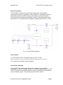
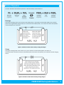
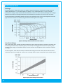
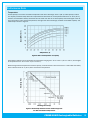
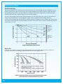
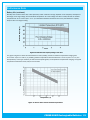
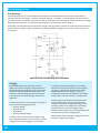
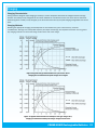
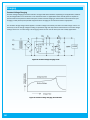
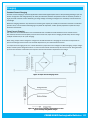
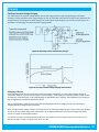
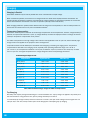
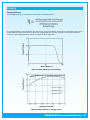
Basic Operation
It is important to note that the SLA battery terminal voltage under load will be lower than the battery terminal voltage when the
load is removed. When the load is removed, the battery voltage rebounds to a higher voltage. The amount of voltage rebound
depends on the load current draw and the state of battery charge.
For example:
A 12V SLA battery supplying a load current of 5A can measure 11V under load after some time, but as soon as the load is removed, the battery voltage can rebound to 12.3V. This effect is taken into account when configuring the SLA-LVP module Early
Warning (E/W) threshold voltage and the Low Voltage Protection (LVP) load cut-off voltage.
The SLA-LVP modules are pre-configured E/W trigger voltage of:
● 11.7V
and a LVP load cut-off voltage of:
● 11.5V
With the above E/W and LVP settings, when the battery voltage drops to 11.7V the E/W is triggered and the module starts
beeping its alarm (or flashes its LED depending on the jumper setting) to signal that battery recharging is required. When the
external power supply is connected to the picoUPS-100-LVP, then the beeping E/W alarm will stop.
If the charging power supply is not connected to the module, the battery voltage continues to drop. Once it reaches the 11.5V
LVP threshold setting, the picoUPS-100-LVP automatically disconnects the load and ends the E/W alarm and is locked in protection mode, preventing further discharge to the battery.
The picoUPS-100-LVP recovers out of protection mode as soon as the 16V external charging power supply is connected to the
picoUPS-100-LVP and the battery is recharged.
The SLA-LVP module may be user reconfigured for alternative E/W and LVP voltage thresholds, via the relevant on-board potentiometers as described in configuration below.
Custom LVP and E/W Configuration
The SLA-LVP module is pre-configured with its E/W and LVP threshold voltages at 11.7V and 11.5 V respectively. With these
settings, the E/W will trigger when the battery voltage drops to 11.7 V and the LVP load cut-off will occur when the battery voltage is at 11.5V.
The LVP hysteresis is set to 1.5V to allow for battery voltage rebound condition when the load is cut-off. Without the hysteresis
allowance, undesired load switching oscillation will occur. From tests, it has been determined that the 1.5V hysteresis is just
greater than the rebound voltage which is desired to prevent oscillation.
Fixed resistors R1 (180K) and R4 (10K) set the hysteresis for LVP and E/W respectively. R1 is the most critical in oscillation
prevention. To increase the hysteresis, a higher value will be used or a lower value for reduced hysteresis.
The “LV set” potentiometer is used to set the LVP cut-off voltage. To change the LVP and E/W voltages, proceed with the steps
on the next page.
Equipment required:
● Variable DC power supply with an output voltage up to 16V
● Voltmeter or multimeter
● Small flat tip screwdriver
2