1
User’s
Manual
A Dual FC-PGA Pentium® III Processors based
AGP mainboard Supports PC133 Memory
TRADEMARKS
All products and company names are trademarks or registered
trademarks of their respectives holders.
These specifications are subject to change without notice.
$ ,)
Manual Revision 1.0
September 14, 2000
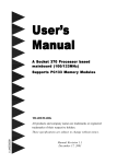
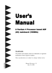
Components Checklist
A
(1)
Mainboard
B
(1)
Uusers manual
C
(1)
Floppy drive cable
D
(2)
ATA-66/100 Hard drive cable
E
(1)
Software drivers set (disks or CD-ROM)
Highpoint 370 Driver & Utility diskete
VIA Driver CD Disk
USERS
MANUAL
A
B
or
E
C
D (2)
Table of Contents
Chapter 1: Introduction
Overview of Main Features .................................................................7
Pentium® III FC-PGA Processor .........................................................9
Accelerated Graphics Port (AGP) ..................................................... 10
ATX Form Factor .............................................................................. 11
Hardware Monitoring ........................................................................ 12
I/O Shield .......................................................................................... 13
Power ON Remotely (KBPO & Modem Ring-in) ............................. 13
Universal Serial Bus (USB) ............................................................... 14
Symmetrical Multi-Processing (SMP) ............................................... 14
System Block Diagram ...................................................................... 16
Chapter 2: Hardware Installation
Directions & Recommended Tools ................................................... 17
Detailed Board Layout ...................................................................... 18
Configuration of Jumpers .................................................................. 19
Installing into ATX case..................................................................... 20
Installing Connectors ......................................................................... 21
Installing Memory ............................................................................. 22
Installing Processor(s) ....................................................................... 24
Device Connector Description ........................................................... 26
Configuring KBPO and Modem Ring-in ........................................... 27
Chapter 3: Software Installation
Included Software & Drivers ............................................................ 29
Microsoft Windows® 95/98 Setup ..................................................... 30
Microsoft Windows® 2000 Setup ...................................................... 33
Microsoft Windows® NT 4 Setup ...................................................... 35
Chapter 4: Award BIOS Setup
BIOS Instructions .............................................................................. 37
Standard CMOS Features ................................................................. 38
Advanced BIOS Features .................................................................. 39
Advanced Chipset Features ............................................................... 44
Integrated Peripherals ........................................................................ 48
Power Management Setup ................................................................ 53
PNP/PCI Configurations ................................................................... 56
PC Health Status ............................................................................... 58
Frequency/Voltage Control ................................................................ 59
Change Supervisor or User Password ............................................... 60
Save & Exit Setup ............................................................................. 61
Exit Without Saving ........................................................................... 61
Chapter 5: HPT370 UltraDMA-100 & RAID
RAID Introduction ............................................................................ 63
Create RAID ..................................................................................... 65
Delete RAID...................................................................................... 66
Duplicate Mirror Disk ........................................................................ 66
Create Spare Disk ............................................................................. 67
Remove Spare Disk ........................................................................... 68
Set Drive Mode ................................................................................. 68
Select Boot Disk ................................................................................ 69
Appendix A: Load Optimized Defaults
Load Optimized Defaults ................................................................. A-1
Appendix B: GHOST 5.1 Quick Users Guide
Ghost 5.1 Quick Users Guide ........................................................ B-1
Additional Sources of Information
HighPoint
http://www.highpoint-tech.com
Intel Corporation
http://www.intel.com
http://developer.intel.com
Microsoft Corporation
http://www.microsoft.com
Page Left Blank
Introduction
Cha
pter 1
Chapter
Intr
oduction & F
ea
tur
es
Introduction
Fea
eatur
tures
Overview of Main Features
The board is a Dual FC-PGA Processors based motherboard. Measuring at 305mm
by 244mm this ATX board supports the fastest performing processors now available:
the Intel FC-PGA Pentium III Coppermine. Standard Front Side Bus options
include 66, 100 & 133MHz.
Teamed with the VIA Apollo Pro133A chipset is support for 4x SDRAM (DIMM)
modules and UltraDMA-66. Additionally for added functionality we has included the
versatile HPT 370 IDE controller to add UltraDMA-100 and IDE RAID.
The HPT370 PCI Dual Channel Ultra DMA/ATA 100 RAID Controller supports up to
4 Ultra DMA/ATA 100 disk devices with a burst transfer rate of up to 100MB/Sec.
The HPT370 is fully backward-compatible with all IDE/ATAPI devices including
Ultra DMA/ATA 66, 33, EIDE Fast ATA-2, IDE drives and CD ROM drives. HPT
370 coexists with motherboard IDE ports, adding two additional IDE/ATAPI ports.
Processor Support
The board is based on the Dual FC-PGA Pentium® III Processors. 66/100/
133MHz Front Side Bus with PPGA / FC-PGA socket 370 packaging. Single
PPGA/FC-PGA Socket370 Celeron processor may also be used.
Chipset
Designed with VIA Apollo Pro133A (133MHz FSB) AGPset (694X + VT82C596B).
Memory
Supports up to 2 Gigabyte of SDRAM (minimum of 32 MB) on board using PC100
memory and 1.5 GB using PC133. The board will support Error Checking and
Correcting (ECC) when using parity SDRAM memory modules. This will detect
multiple bit errors and correct 1-bit memory errors.
Expansion Slots
Supports (1) 16 bit ISA slot, (5) 32 bit PCI slots, and (1) AGP slot. The board
2=CA%
Introduction
supports (5) PCI Bus Master slots and a jumperless PCI INT# control scheme
which reduces configuration confusion when plugging in PCI card(s).
IDE Bus Master UltraDMA-66 & UltraDMA-100 RAID
VIA Apollo Pro133A chipset provides two (2) standard independent high performance PCI IDE interfaces capable of supporting PIO Mode 3/4 and UltraDMA-66
devices. With the addition of the HPT370 IDE chipset two (2) extra IDE ports are
also included - adds UltraDMA-100 & IDE Raid functionality. Four (4) IDE/Atapi
devices supported on the VIA UltraDMA-66 controllers and four (4) supported on
the HPT370 UltraDMA-100/RAID controllers. All ports are backwards compatible
with UltraDMA-66, UltraDMA-33 and PIO Modes 3/4.
Super Multi I/O
Designed with Winbond W83977EF-AW Multi I/O: (1) floppy port, (1) parallel
port (EPP, ECP), and (2) serial ports (16550 Fast UART), (1) IrDA. Includes a PS/
2 mouse connector. Allows use of a PS/2 or AT keyboard (with optional adapter).
BIOS
Features Award Plug & Play BIOS for easy flash upgradability. Features the newer
Award v6.0 interface allowing better compatibility and support for todays hardware.
The BIOS setup options are backed-up via the use of a Lithium battery which
provides environmental protection and longer battery life.
USB
Supports the Universal Serial Bus (USB) connector. The onboard VIA chip provides
the means for connecting PC peripherals such as keyboards, joysticks, telephones,
and modems.
Built-in ATX 20-pin power supply connector.
Supports ring-in feature - system can be turned on remotely using external modem.
Power on by Alarm - Allows your system to turn on at a preselected time.
Supports Hot Key, Any Key, or password Keyboard power ON function (KBPO).
Built-in WOL (Wake On Lan) and WOM (Wake On Modem) Connectors.
2=CA&
Introduction
Pentium III FC-PGA Processor
Intels latest Pentium® III processors are designed using the highly advanced 0.
18-micron process. This new generation of technology brings all the performance-enhancing features of the Pentium III processor into exciting new PC
products. This redesigned Pentium III processor with Advanced Transfer Cache
means you have all the power and performance for todays and tomorrows
Internet applications.
The Pentium III processor is designed for high-performance workstations and
servers. It is binary compatible with previous Intel processors. The Pentium III
provides supreme performance for any applications running on advanced
operating systems such as Windows NT and Windows 2000. This is made
possible by the best features of Intel Processors -- Advanced Transfer Cache,
Dual Independent Bus (DIB), streaming SIMD extensions, Dynamic execution,
and much more.
Scalable from one to two processors in a multiprocessor system the Pentium III
extends the power of previous generation processors with enough processing muscle to
satisfy the most intensive applications. The Intel Pentium III processor for FC-PGA
(PGA370) socket is the next member of Intels P6 family of processors. This processor
uses the same core and offers the same if not better performance as the Intel Pentium
III processor for the SC242 (Slot 1), but utilizes a newer packaging type called flip-chip
pin grid array (FC-PGA).
Key features of Pentium III FC-PGA:
System bus frequency of 100MHz or 133MHz.
Available in versions that incorporate 256KB Advanced Transfer Cache with ECC.
Dual Independent Bus (DIB) architecture: Seperate dedicated external system bus
and dedicated internal high-speed cache bus.
Internet Streaming SIMD Extensions.
Dynamic execution micro architecture.
Intel Processor Serial Number.
Power Management capabilities.
System Management mode.
Optimized for 32-bit applications running on advanced 32-bit operating systems.
Error-correcting code for system bus data.
Enabled systems which are scalable for up to two processors.
2=CA'
Introduction
Accelerated Graphics Port (4X AGP MODE)
The Accelerated Graphics Port (more commonly known as AGP) interface is a new
platform bus specification that enables high performance graphics capabilities, especially 3D. This interface specification will enable 3D applications, which not only
require sufficient information storage so that the monitor image may be refreshed, but
also enough storage to support texture mapping, z-buffering and alpha blending.
PCI will continue to be the main general-purpose system I/O bus. The AGP interface
has been designed specifically for dedicated use by graphics controllers, and is not
intended to replace PCI. It is physically separated from the PCI bus and it uses a
separate connector.
The benefits of AGP:
1. Direct texturing from main memory:
-Two memory pipes are provided to graphic engines for concurrency.
-Richer textures with no frame buffer growth.
-Graphics & CPU get a continuous view of graphic data structures from GART
(Graphics Address Re-mapping Table) Hardware.
2. De-multiplexed address and data.
-Enables pipelining and concurrency.
3. 533 Mbytes /s peak bandwidth. -Delivers high performance data control.
4. Peak bandwidth can be 4 times the PCI bus bandwidth, and higher sustained rates
via Sideband and pipelining.
5. Direct Memory Execute Textures.
6. Reduced Contention with the CPU and I/O devices for bus and memory access.
The PCI bus serves disk controllers, LAN chips, and possibly video capture. AGP
operates concurrently with and independent from most PCI operations.
Furthermore, the CPU can accesses system RAM while with the AGP graphic chip
reads RAM, because of out-of-order queuing hardware support in the chip set.
Therefore, in spite of the heavy access from the graphic chip, there should be no
audio breakup or other CPU degradation.
7. A separate port for the graphics chip to access memory, which allows for concurrent
texture reads from AGP memory while read/writing from local memory. Efficient
utilization of the bandwidths allows the graphic chip to obtain 1.3 GB/s peak by
using both ports simultaneously, versus 0.8 GB/s from the local RAM.
8. Allowing the CPU to write directly to AGP shared system memory.
2=CA
Introduction
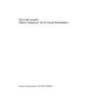
ATX Form Factor
The board is designed with ATX form factor - the latest industry standard of chassis.
The ATX form factor is essentially a Baby-AT baseboard rotated 90 degrees within the
chassis enclosure and a new mounting configuration for the power supply. With these
changes the processor is relocated away from the expansion slots, allowing them all to
hold full length add-in cards. ATX defines a double height aperture to the rear of the
chassis which can be used to host a wide range of onboard I/O. Only the size and
position of this aperture is defined, allowing PC manufacturers to add new I/O features
(e.g.; TV input, TV output, joystick, modem, LAN, audio, etc.) to systems. This will
help systems integrators differentiate their products in the marketplace, and better
meet your needs.
By integrating more I/O down onto the board and better positioning the hard drive
and floppy connectors material cost of cables and add-in cards is reduced.
By reducing the number of cables and components in the system, manufacturing
time and inventory holding costs are reduced and reliability will increase.
By using an optimized power supply, it's possible to reduce cooling costs and lower
acoustical noise.
Chassis fan for
system (airflow
comes into system)
Expandable I/O
Full length
slots
ATX Power
Supply (airflow
leaves system)
Easy to access
memory modules
Floppy / IDE
connectors
close to
peripheral
bays
3 1/2"
Bay
5 1/4"
Bay
ATX power
connectors
Figure 1
2=CA
Introduction
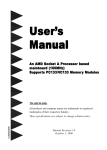
To implement the built-in remote on/off function of the ATX power supply a momentary switch, which is normally open, should be connected to the PW-ON connector on
the motherboard as the on/off switch.
Based on the ATX form factor the board has been designed to support many ACPI and
soft-off functions. According to the definition of ACPI: suspend mode will be enabled
while pressing the system on/off button for less than 4 seconds. Nevertheless the
system can always be turned off by pressing the system on/off button for more than 4
seconds or by using the soft-off function if supported by the operating system.
ATX
POWER SUPPLY
J3
Case (chassis) Power
ON/OFF button (J 3)
Figure 2: Simple ATX Power ON/OFF Controller
Hardware Monitoring
Hardware monitoring allows you to monitor various aspects of your systems operations
and status. These include features such as CPU temperature, voltage and fan RPMs.
By entering the Award BIOS CMOS utility and selecting the PC Health section you can
monitor this information.
2=CA
Introduction
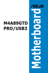
I/O Shield
The board is equipped with an I/O back panel. Please use the appropriate I/O shield.
Parallel Port
Figure 3:
I/O back
panel layout
PS/2 Mouse
PS/2 Keyboard
USB
COM1
COM2
Power ON Remotely
Keyboard power on (KBPO)
The Keyboard Power-On (KBPO) function allows users to turn on a PC by easily
touching the keyboard instead of bending down to look for the power button under a
table. To use this unique feature your motherboard have it set to enable, and use an
ATX power supply rated 0.1a (100mA) or greater for the +5vsb. KBPO is only
available on selected motherboard models.
Modem Ring-IN
On the basis of bounded functions in the I/O chipset, the two onboard serial ports are
able to support external modem ring-in power-on. Using external modems users are
now able to power on the system simply by placing a call to the system remotely.
Wake On Lan (WOL)
This new technology provides the ability to remotely power on the system using special
network data packets sent over a LAN. WOL requires both a network interface card
(NIC) that supports it and software [not included] that sends the special network
packets.
Wake On Modem (WOM)
Similar to WOL above specially made internal modems can be installed and connected
to the motherboard through the WOM connector. Then by simply calling your computer from a remote location can cause the system to power on.
2=CA!
Introduction
Universal Serial Bus (USB)
USB is a peripheral bus specification developed by the PC and telecom industries
that brings plug and play of computer peripherals outside the box, eliminating the need
to install cards into dedicated computer slots and reconfigure the system.
Personal computers equipped with USB allow computer peripherals to be automatically
configured as soon as they are physically attached - without the need to reboot or run
setup. USB also allows multiple devices to run simultaneously on a computer, with
peripherals such as monitors and keyboards acting as additional plug-in sites, or hubs.
Symmetrical Multi-Processing (SMP)
At last an Enterprise-Class solution for your Bandwidth Critical applications server at
PC prices. This mainboard features the latest Intel Pentium® III Processor horsepower
in a Symmetrical Multi-Processing (SMP) configuration previously only available on
RISC and Mainframe systems.
In SMP Operating Systems such as Unix® and Windows® NT the two main tasks of I/
O and Application thread can be most efficiently done if split evenly over two CPUs.
The core benefit to you is not only the reduced outlay in infrastructure, but also the
PC-architecture that you need for security of investment and future compatibility.
This mainboard is also an excellent single-user Workstation solutions for MissionCritical 32-bit applications such as Adobe® Photoshop for Windows® NT, where double
floating-point power can really smooth out your work-load. Also provided are the
latest PC Workstation technologies including A.G.P., USB, and PC2.1 Expansion
Slots.
NOTE: Not all FC-PGA Intel Pentium III processors support dual CPU operation.
Please refer to processor documentation or Intels website for more information. to be
more specific http://www.intel.com
2=CA"
Introduction
Operating Systems that support Dual Processing
Ope rating Sys te m
Ve rs ion
D ual CPU Supporte d?
Linux
All
N o, may be supported in the future.
N etware SMP
4.11 or above
Yes.
O S/2 SMP
2.11
N o, may be supported in the future.
SCO Unix MPS
3 .0
N o, may be supported in the future.
SCO Unix O penserver
5 .0
N o, may be supported in the future.
Solaris
2.4/2.5
N o, may be supported in the future.
Unixware
2.0x/2.1
N o, may be supported in the future.
Windows 95
All
N o, dual CPU not supported.
Windows 98
All
N o, dual CPU not supported.
Windows N T Workstation
3.51 or above
Yes.
Windows N T Server
3.51 or above
Yes.
Windows 2000 Professional
All
Yes.
Windows 2000 Server
All
Yes.
Windows 2000 Advanced Server
All
Yes.
Table 1: SMP O/S support
2=CA#
Introduction
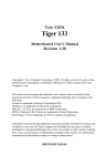
System Block Diagram
FC-PGA
Pentium III
Processor
FC-PGA
Pentium III
Processor
133/100/66MHz
66 MHz
4X AGP Bus
AGP Slot
Graphic
Video
PAC
PCI Bridge
& memory
Controller
VT82C694X
MA [0:14]
MD [0:63]
MPE [0:7]
VT82C596B
I/O Bridge
PCI Slots
USB 0 & 1
Serial Port 1
Serial Port 2
LPT Port
PS/2 Mouse
PS/2
Keyboard
133/100/66 MHz
BIOS
Flash Memory
IDE Devices
Primary &
Secondary
ISA Slots
Winbond
83C977
Floppy
Drives
Figure 4: System block diagram
2=CA$
HPT370
IDE4
ATA100 with
Raid
IDE3
H.D.
H.D.
H.D.
H.D.
Hardware Installation
Cha
pter 2
Chapter
d war
e Installa
tion
Hard
are
Installation
Har
Directions & Recommended Tools
This chapter will discuss some general steps needed in order to get your new
mainboard installed and operational. The board is a high performance mainboard
which allows the use of Dual Intel Pentium III FC-PGA processors. Below you will
find our recommended installation procedure for fast and easy setup.
Step 1 - Configuration of Jumpers ..................................................... 19
Step 2 - Installing into ATX case ....................................................... 20
Step 3 - Installing Connectors ............................................................ 21
Step 4 - Installing Memory ................................................................ 22
Step 5 - Installing Processor(s) .......................................................... 24
Step 6 - Configuring KBPO & Alternate Power On Methods ........... 27
When the system is completely assembled and ready for use move on to chapter 3 for
software installation and recommended drivers.
Recommended Tools (Not Included)
Needle nose pliers: the all purpose needle nose
pliers is useful for many purposes such as, tightening
loose standoffs when no socket is available, holding
screws & jumpers, cutting plastic tie-offs, etc.
Phillips and flat-head screwdrivers: useful for the
actual mouting of the mainboard itself to the case as
well as hard drives, cards, CD-ROM drives, etc.
2=CA%
Hardware Installation
Detailed Board Layout
2=CA&
Hardware Installation
Configuration of Jumpers
Jumpers are small plastic-encased conductors that are used to slip over a pair of
jumper pins. We designs all mainboards with the fewest jumpers and pins to make
your setup fast and easy. It is recommended that the jumpers be set before the
mainboard is installed into the case because access to the jumpers will be easier. The
following will describe all of the jumpers that are required to be set before moving on.
Note: The jumpers as shown below are in their correct physical orientation.
1
CMOS Clear
JP1:
= 1-2 - Normal (Default)
= 2-3 - Clear CMOS
1
CPU Speed Selection
JP3:
= 1-2 - 66MHz FSB
= 2-3 - 100/133MHz FSB (Default)
JP1:
JP3:
(133MHz FSB if supported by CPU will automatically be selected. Jumper will be
ignored.)
JP13:
1
Keyboard Power-ON function (see page 31)
JP13:
= 1-2 - Enable
= 2-3 - Disable (Default)
Based on the implementation of the VIA Apollo Pro133A AGPset the board provides
66, 100, or 133MHz for FC-PGA processors and memory operations. The primary
and secondary processor slots both operate synchronously, therefore if two processors
are used both will need to be of the same type and speed. When using the 100MHz
FSB all memory must be PC100 or PC133 compliant SDRAM. 133MHz FSB requires
PC133 compliant SDRAM at all times.
Memory is an important component of any motherboard. When selecting memory for
use on your motherboard we recommend using only the finest quality modules. We
would like to stress that using non-compliant SDRAM modules with a 100 or 133MHz
FSB severely compromises the integrity of the system.
NOTE: Not all FC-PGA Intel Pentium III processors support dual CPU operation.
Please refer to processor documentation or Intels website for more information.
http://www.intel.com
2=CA'
Hardware Installation
Installing into ATX case
Static electricity can severely damage your equipment. Handle the board and any other
device in your system with extreme care and avoid unnecessary contact with system
components on the mainboard. Always work on an antistatic surface to avoid possible
damage to the mainboard from static discharge. Always have the power supply
unplugged and powered off when inserting and removing devices within the computer
chassis.
There are countless types, sizes, and shapes when it comes to cases in the computer
industry. Generally the mainboard is mounted into the case using nylon and/or brass
standoffs. These standoffs prevent the mainboard from actually touching the case
itself (shorting) and additionally provides support to prevent bending and warping of the
board during normal use.
1. Observe the safety precautions as listed above.
2. Place the I/O shield into the I/O connector area of the case. An ATX 2.1 compliant
I/O shield should be provided with the system case. The shield is ensures proper
cooling and also minimizes EMI.
3. Position the board over the standoffs and slide the motherboard into place noting
that the I/O connectors on the mainboard should protrude slightly through the I/O
shield.
4. Connect any IDE or Floppy drive cables now onto the mainboard. Always observe
the correct orientation of the cables. PIN1 on the cable is signified by a color stripe.
Connect ATX cable(s) from power supply to mainboard (PW1).
5. Install any add-in boards; fully seating them into their respective slots.
6. Move on to the next section to connect case switches and LEDs.
2=CA Hardware Installation
Installing connectors
Speaker
Reset
J2
Pwr LED & Keylock
Infrared
J3
IDE & Turbo Power On/Off
The computer case may supply additional wires which control the function of the
power switch, hard drive LED, power LED and reset among others. This section
outlines where on the mainboard these wires should be attached. PIN1 is designated as
a 1 or + unless otherwise noted.
1
Power On/Off - This is connected to the power button on the case.
Using the Soft-Off by Pwr-BTTN feature, you can choose either
Instant Off (turns system off immediatly), or 4 sec delay (you need to
hold the button down for 4 seconds before the system turns off). When
the system is in 4 sec delay mode, we has added a special feature to
make the system go into suspend mode when the button is pressed
momentarily. See page 54.
+ Turbo LED indicator - LED ON when higher speed is selected
IDE LED indicator (UltraDMA-66 controller) - LED ON when Onboard
+ PCI IDE Hard disks is activated.
Infrared - Infrared connector
1. Vcc
4. GND
2. IRTX
5. IRTX2
3. IRRX2
1
KeyLock - Keyboard lock switch & Power LED connector
1. Power LED(+) 4. Keylock
2. N/C
5. GND
1
3. GND
Speaker - Connect to the system's speaker for beeping
1. Speaker 3. GND
1
2. N/C
4. GND
1 Reset - Closed to restart system.
2=CA Hardware Installation
Installing Memory
The board supports 168-pin SDRAM DIMMs (Dual In-line Memory Module).
(4) supported using PC100 (100 MHz), and (3) supported using PC133 (133 MHz).
SDRAM DIMM (modules) may be 16MB, 32MB, 64MB, 128MB, 256MB or 512MB.
DRAM components (IC on module) may be 1M, 2M, 4M, 8M, 16M, 32MxN, 256MB.
Use of PC133 SDRAM limits number of DIMM slots that can be used to 3 (table II below).
2GB MAX DRAM (using 256MB DRAM components) supported at 100MHz (table I below).
1.5GB MAX DRAM (using 256MB DRAM components) supported at 133MHz (table II below).
EDO, buffered and registered memory not supported. For best stability do not mix PC100 and PC133.
Table I - Possible memory configuration using PC100 SDRAM through DIMM1 to
DIMM4.
Total Me mory
DIMM 1
DIMM 2
DIMM 3
DIMM 4
= 2GB
Maximum
(100MHz)
SDRAM 32MB 64MB, SDRAM 32MB 64MB,
128MB, 256MB,
128MB, 256MB,
512MB
512MB
X1
X1
SDRAM 32MB 64MB,
128MB, 256MB,
512MB
X1
SDRAM 32MB 64MB,
128MB, 256MB,
512MB
X1
= 1.5GB
Maximum
(100MHz)
SDRAM 32MB 64MB,
128MB, 256MB,
512MB
X1
SDRAM 32MB 64MB,
128MB, 256MB,
512MB
X1
SDRAM 32MB 64MB,
128MB, 256MB,
512MB
X1
None
= 1GB
Maximum
(100MHz)
SDRAM 32MB 64MB,
128MB, 256MB,
512MB
X1
SDRAM 32MB 64MB,
128MB, 256MB,
512MB
X1
None
None
= 512MB
Maximum
(100MHz)
SDRAM 32MB 64MB,
128MB, 256MB,
512MB
X1
None
None
None
Table II - Possible memory configuration using PC133 SDRAM through DIMM1 to
DIMM3 only.
Total Me mory
DIMM 1
DIMM 2
DIMM 3
DIMM 4
= 1.5GB
Maximum
(133MHz)
SDRAM 32MB 64MB,
128MB, 256MB,
512MB
X1
SDRAM 32MB 64MB,
128MB, 256MB,
512MB
X1
SDRAM 32MB 64MB,
128MB, 256MB,
512MB
X1
None
= 1GB
Maximum
(133MHz)
SDRAM 32MB 64MB,
128MB, 256MB,
512MB
X1
SDRAM 32MB 64MB,
128MB, 256MB,
512MB
X1
None
None
= 512MB
Maximum
(133MHz)
SDRAM 32MB 64MB,
128MB, 256MB,
512MB
X1
None
None
None
2=CA
Hardware Installation
DIMM Module Installation & Removal
Figure 1 displays the notch marks and what they should look like on your DIMM
memory module.
DIMMs have 168-pins and two notches that will match with the onboard DIMM
socket. DIMM modules are installed by placing the chip firmly into the socket at a 90
degree angle and pressing straight down (figure 2) until it fits tightly into the DIMM
socket (figure 3).
Figure 1
LEFT KEY ZONE
(UNBUFFERED)
CENTER KEY ZONE
(3.3 V DRAM)
Figure 2
Open DIMM module clip before installing DIMM. When
DIMM is inserted the clip will raise into closed position.
Figure 3
To remove the DIMM module simply press down both
of the white clips on either side and the module will be
released from the socket.
2=CA !
Hardware Installation
Installing Processor(s)
The board supports maximum two Intel Pentium III FC-PGA processors or one
PPGA/FC-PGA 370 Celeron. This section outlines the procedure to install one or two
processors into the mainboard. As newer processors are released we will test for
compatibility. For a list of currently tested and validated processors please visit our
website.
1. Observe the safety precautions as listed on
page 24 for handling static sensitive devices.
2. Open the socket by raising the actuation lever.
3. Insert the processor. Ensure proper pin 1
orientation by aligning the FC-PGA corner
closest to the actuation arm tip. The pin field
is keyed to prevent misoriented insertion. Do
not force the processor into the socket. If it
does not go in easily check for mis-orientation,
debris or bent pins. Make sure the processor is
fully inserted into the socket on all sides.
4. Close the socket by lowering and locking the
actuaution lever.
2=CA "
Hardware Installation
5. Attach FAN/Heatsink.
6. If 3-pin fan power cables are present they may be attached to either J4 or J5.
7. Repeat steps to insert second processor if present.
8. Check JP3 to set the Front Side Bus. Not required for 133MHz. Since Intel processors are multiplier locked there is no need to adjust any multiplier.
Note: Intels reference design thermal soluion is an active heatsink; an extruded
aluminum heatsink base and a fan attached to the top of the fin array.
2=CA #
Hardware Installation
Device Connector Descriptions
12345678901234567890123456789012123456789012345678901234567890121234567890123456789012345
12345678901234567890123456789012123456789012345678901234567890121234567890123456789012345
PS/2 Mouse
(Top)
PS/2 Keyboard
(Bottom)
USB 1
(Top)
USB 0
(Bottom)
Parallel Port
(Top)
Com1
(Bottom Left)
Figure 8
Com2
(Bottom
Right)
AGP1:
AGP slot
BAT1:
Battery Holder (3v Lithium Cell)
DIMM1~4: SDRAM DIMM slots
FDD1:
Floppy controller
IDE1:
Primary IDE (UltraDMA-66 on VIA chipset)
IDE2:
Secondary IDE (UltraDMA-66 on VIA chipset)
IDE3:
Primary IDE (UltraDMA-100/RAID on Highpoint HPT 370 chipset) (Blue Color)
IDE4:
Secondary IDE (UltraDMA-100/RAID on Highpoint HPT 370 chipset) (Blue Color)
J2 ~ 3:
Chassis panel connector HDD LED)
J4:
CPU 1 fan power (allows RPM monitoring)
J5:
CPU 2 fan power (allows RPM monitoring)
J6:
Chassis fan power (allows RPM monitoring)
J7:
Wake On-Lan (WOL)
J8:
Wake On-Modem (WOM)
JP1:
CMOS clear
JP3:
CPU speed select
JP13:
Keyboard power-on (KBPO)
LPT1:
Serial ports & parallel port
PCI1 ~ 5: PCI slots
PS1:
PS/2 connectors for keyboard (bottom) and mouse (top)
PW1:
ATX power supply connectors
RT1:
Primary CPU temperature sensor
RT2:
Secondary CPU temperature sensor
RT3:
System temperature sensor
SL1/SL2: ISA Slot
USB1:
USB ports
2=CA $
Hardware Installation
Configuring KBPO & Alternate Power On Methods
Keyboard power on (KBPO)
The Keyboard Power-On (KBPO) function allows users to turn on a PC by easily
touching the keyboard instead of bending down to look for the power button under a
table. To use this unique feature your motherboard have it set to enable, and use an
ATX power supply rated 0.1a (100mA) or greater for the +5vsb.
0.1a (100mA) is the bare minimum required for KBPO; in actuality 0.72a (720mA) or
greater is preferred as some devices and keyboards may have a negative effect on
lower current power supplies causing KBPO not to function correctly.
To enable KBPO:
1. Press the power on/off switch to turn on the system and then push again and hold
for more than 4 seconds to turn power back off.
2. Move the KBPO jumper (JP13) to the enable position to activate the function. You
now can enjoy the Keyboard Power-ON function by pressing any 1 or 2 keys at the
same time for 1-2 seconds on the keyboard. After releasing the keys the system will
then power on.
Notes:
1. If the ATX power supply cable is removed from the motherboard at any time then
the above procedure will need to be repeated. Disable the KBPO jumper than
follow steps above.
2. The number of keys needed to turn on the system may vary depending upon
internal keyboard designs. This is due to the different current loading characteristic
of different keyboard designs. Additionally the keystrokes used may be modified in
the BIOS.
Modem Ring-IN
On the basis of bounded functions in the I/O chipset, the two onboard serial ports are
able to support external modem ring-in power-on. Using external modems users are
now able to power on the system simply by placing a call to the system remotely.
Simply enable Power On by Ring and set Modem Use IRQ in the Award BIOS
CMOS utility under the Power Management section.
2=CA %
Hardware Installation
Page Left Blank
2=CA &
Software
Cha
pter 3
Chapter
Softw
ar
e Installa
tion
Softwar
are
Installation
Included Software & Drivers
All drivers required for installation of the mainboard under Windows 95/98, NT 4, and
Windows 2000 are located on the included floppy disks (or CD-ROM). Additionally
drivers and manuals are also available on our website.
If you wish to take advantage of Accelerated Graphics Port (AGP) video cards your
system will require at least Windows 95 OSR2.1, Windows 98, or Windows 2000.
OSR2.0 versions of Windows 95 can be updated to OSR2.1 by installing the USB
supplement patch available from your computer vendor or Microsoft. If you use
Windows 95 OSR2.0 or older without updating then you cannot use AGP or USB
functions.
Bus mastering and UltraDMA (ATA-66) drive support can be enabled within Windows
95 and Windows NT by installing the included VIA Bus Mastering drivers. Windows
98/2000 users need not install the driver as these functions are already supported by
default.
Drive boot priority is determined what controller is selected. To have your hard drive
attached to the HTP370 UltraDMA-100/RAID controller boot instead of the VIA
UltraDMA-33 select SCSI for the Second Boot Device in the CMOS under Advanced BIOS Features. It is suggested to keep the First Boot Device reserved for your
CD-ROM or Floppy Disk Drive (FDD).
Copyright notice
The software on disks and/or CD is owned and copyrighted by respective owner or its
third party suppliers. You may not disassemble or decompile the software unless our
prior written consent is obtained.
2=CA '
Software
Microsoft Windows 95/98 Setup
Installation of Windows 95 is a fairly simple task but for proper system operation a
few key drivers should be installed. This section highlights what drivers are necessary
and in what order they should be installed during the setup process.
Also note if you wish to take advantage of Accelerated Graphics Port (AGP) video
cards your system will require at least Windows 95 OSR2.1 or Windows 98. OSR2.0
versions of Windows 95 can be updated to OSR2.1 by installing the USB supplement
patch available from your computer vendor or Microsoft. If you use Windows 95
OSR2.0 or older without updating then you cannot use AGP or USB functions.
Windows 95/98(SE) does not support dual processing (second processor will be
ignored).
1: Install Windows 95/98(SE).
2: Install USB Support if not automatically installed. (AGP/USB users only. All
other may skip to step 3.)
3: Install VIA Service Pack (VIA 4 in 1). This utility updates Microsoft operating
systems so that they may properly identify and configure the latest VIA Apollo
Pro133A AGPset.
Use the included autorun driver CD-ROM and select VIA Service Pack (VIA 4 in
1). Install all components recommended by the utility.
4: HighPoint HPT370 driver for UltraDMA100/RAID controller.
1.
Windows 95/98 must be installed on the system prior to installing the driver.
2.
Close any running applications.
3.
Open "My Computer".
4.
Double click on the "Control Panel" icon.
5.
Double click on the "System" applet.
6.
Double click on the PCI Mass Storage Controller device.
7.
Click on the Drivers tab.
8.
Click on Update Driver... or Change Driver... button.
2=CA!
Software
9.
Click on the "Next" button.
10.
There is a window that ask you "Do you want Windows to do?", choose
"Display a list of all the driver in a specific location, so you can select the
driver you want" then click on the "Next" button.
11.
There is a Window listing hardware types, select the "SCSI controllers" then
click on the "Next" button.
12.
Put the install diskette into the drive A: and then click on the "Have Disk..."
button.
13.
Key in Path A:\Win than click on the OK button.
14.
Click on the "OK" button.
15.
Click on the "Next" button.
16.
If there is a window showing the settings (resources) to be used by the driver,
then click on the "Next" again. At this point, the system will install the driver.
17.
Click on the "Finish" button.
18.
Then the system will ask you to restart the system. If the settings reported in
step 15 are not what set on the host adapter, you must adjust the settings by
using the device manager in the System control panel before restarting your
computer.
5. Install HighPoint (HPT370) Disk Array monitoring utility (OPTIONAL). Located
on the Driver Disk or CD-ROM in the HPT370\UTIL folder is an utility that reports
information about the status of any RAID array created by the HighPoint controller.
Use SETUP.EXE in HPT370/UTIL to install..
6: Install Video Cards driver.
7: Install DirectX. This is available from Microsoft at http://www.microsoft.com.
8: Congratulations basic installation complete! You now may continue to install any
additional drivers for other devices. At this time you may wish to check for any
devices listed with question marks (?) in the Device Manager [Control Panel /
System icon] that had no drivers built-in during Windows installation.
2=CA!
Software
Additional information
Hardware Requirements for Multiple Display Support in Win98 (Q182708)
http://support.microsoft.com/support/kb/articles/Q182/7/08.asp
How to Enable Multiple Display Support Using Windows 98 (Q179602)
http://support.microsoft.com/support/kb/articles/Q179/6/02.asp
2=CA!
Software
Windows 2000
Unlike Windows releases, Windows NT & 2000 supports a Dual Processing
environment. Therefore if you wish to obtain extra performance from your system
using a second processor Windows 2000 or Windows NT 4.0 is a better platform.
Please note that directions below unless otherwise specified pertain to all releases of
Windows 2000 (Professional, Server, and Advanced Server).
1: Install Windows 2000. Follow Microsoft directions for installation. If you are
installing from CD-ROM you may now boot directly from the Windows 2000 CD
and begin installation right away. No more bootable floppy disks or DOS real mode
CD drivers needed! (Atapi EIDE CD drives and CD versions only.) See page 44
for enabling this feature (boot sequence).
When Windows 2000 setup starts it will prompt press F6 to install SCSI/RAID, at
this moment press the <F6> function key. When prompted press <S> to specify
additional driver. Insert the HPT370 driver disk and install the driver following the
onscreen prompts.
During Windows 2000 installation the setup program will detect the computer type.
For both single and dual processing configurations the board should use ACPI
Multiprocessor PC.
2. Install HighPoint (HPT370) Disk Array monitoring utility (OPTIONAL). Located on the Driver Disk or CD-ROM in the HPT370\UTIL folder is an utility that
reports information about the status of any RAID array created by the HighPoint
controller. Use SETUP.EXE in HPT370/UTIL to install..
3: Congratulations basic installation complete! You now may continue to install any
additional drivers for other devices.
4: Install Video Cards driver.
5: Install DirectX. This is available from Microsoft at http://www.microsoft.com.
6: Congratulations basic installation complete! You now may continue to install any
additional drivers for other devices. At this time you may wish to check for any
2=CA!!
Software
devices listed with question marks (?) in the Device Manager [Control Panel /
System icon] that had no drivers built-in during Windows installation.
Installing HighPoint HPT370 driver after Windows 2000 was already installed.
1.
Close any running applications.
2.
Open "My Computer".
3.
Double click on the "Control Panel" icon.
4.
Double click on the "System" applet.
5.
Click on the "Hardware" button.
6.
Click on the "Device Manager" button.
7.
There is a Window listing hardware types, select the "SCSI and RAID
controllers" then double click it.
8.
There is a Window listing drivers types, select the "HPT370 UDMA/ATA100
controllers" then click the right key of mouse.
9.
Double Click on the "Properties".
10.
Click on the "Driver" button.
11.
Click on the "Update Driver" button.
12.
Select "Search for a suitable driver for my device", then Click on the "Next"
button.
13.
Select "Floppy disk drivers" and Insert the HPT370 Windows 2000 driver
disk into A:. then Click on the "Next" button.
14.
The wizard found HPT370 UDMA/ATA100 Controllers, Click on the "Next"
button.
15.
To Continue, Click on the "Next" button.
16.
Completing the Upgrade Device Driver Wizard. Click on the "Finish" button.
17.
Restart the System.
Additional information
How to Back Up and Restore the System State Using the Windows 2000
Backup Program (Q240363)
http://support.microsoft.com/support/kb/articles/Q240/3/63.ASP
2=CA!"
Software
Windows NT 4 Setup
Unike Windows releases, Windows NT & 2000 supports a Dual Processing
environment. Therefore if you wish to obtain extra performance from your
system using a second processor Windows 2000 or Windows NT 4.0 is a better
platform.
Please note that currently Microsoft will only support AGP & USB functions when the
operating system is Windows 95 OSR2.1 (or newer), Windows 98, or Windows NT 5.
0 (a.k.a. Windows 2000). These operating systems are programmed to support AGP
functions using separate independent VxD miniport drivers from VGA drivers, through
API. However, under Windows NT 4.0 the AGP functions are not defined in the API.
Therefore if an AGP card is used in the system it will function equivalent to PCI
performance.
1: Install Windows NT 4 and HighPoint HPT370 driver for UltraDMA100/RAID
controller. Follow Microsoft directions for installation. To properly install Windows
NT with the HPT370 driver we recommend using the disk install method only. Do
not install using a bootable CD-ROM.
When Windows NT setup starts up press the <F6> function key. When prompted
specify and additional driver. Insert the HPT370 driver disk and install the driver
following the onscreen prompts.
During Windows NT 4 installation the setup program will detect the computer type.
For both single and dual processing configurations the board should use MPS
Multiprocessor PC.
After completion of Windows NT installation we suggest installing Service Pack 3 or
above from Microsoft.
2: Install VIA Service Pack (VIA 4 in 1). This utility updates Microsoft operating
systems so that they may properly identify and configure the latest VIA Apollo
Pro133A AGPset.
Use the included autorun driver CD-ROM and select VIA Service Pack (VIA 4 in
1). Install only the IDE/Atapi Bus master component. Uncheck all the rest of the
components as they are not supported under Windows NT.
2=CA!#
Software
3. Install HighPoint (HPT370) Disk Array monitoring utility (OPTIONAL). Located
on the Driver Disk or CD-ROM in the HPT370\UTIL folder is an utility that reports
information about the status of any RAID array created by the HighPoint controller.
Use SETUP.EXE in HPT370/UTIL to install..
4: Congratulations basic installation complete! You now may continue to install any
additional drivers for other devices.
Installing HighPoint HPT370 driver after Windows NT was already installed.
1.
Put the Windows NT4.0 CD-Title into the CD-ROM and Boot from the CDROM.
2.
Press <F6> when the message Setup is inspecting your computer hardware
configuration.....
3.
When the Windows NT Setup windows is generated, press S to add a
specify additional device.
4.
Insert the install diskette into Driver A: and then press Enter.
5.
Select HPT370 UDMA/ATA100 RAID Controller for WinNT4.0 then
press <Enter>.
Note: for CD installations, if using an ATAPI CD-ROM, you must be
using the IDE Controller.
6.
Follow the normal setup installation procedure.
Additional information
Boot Partition Created During Setup Limited to 4 Gigabytes (Q119497)
http://support.microsoft.com/support/kb/articles/q119/4/97.asp
2=CA!$
BIOS setup
Cha
pter 4
Chapter
Awar
d BIOS Setup
ard
BIOS Instructions
Awards ROM BIOS provides a built-in setup program which allows the user to modify
basic system configuration and hardware parameters. The modified data will be stored
in a battery-backed CMOS, so that data will be retained even when the power is turned
off. In general, the information saved in the CMOS RAM will stay unchanged unless
there is a configuration change in the system, such as hard drive replacement or a device
is added. It is possible for the CMOS battery to fail, this will cause data loss in the
CMOS only. If this does happen you will need to reconfigure your BIOS settings.
To enter the CMOS setup utility power on the computer and press the <Del> key
immediately, this will bring you into the BIOS CMOS SETUP UTILITY.
The menu displays all the major selection items. Select the item you need to reconfigure.
The selection is made by moving the cursor (press any direction key ) to the item and
pressing the Enter key. An on-line help message is displayed at the bottom of the screen
as the cursor is moved to various items which provides a better understanding of each
function. When a selection is made, the menu of the selected item will appear so that the
user can modify associated configuration parameters.
Figure 1: CMOS Setup Utility
2=CA!%
BIOS Setup
All screen captures shown in this chapter as well as BIOS settings are from the initial
production release BIOS. From time to time We updates BIOS releases therefore actual
options and screens may differ slightly.
Standard CMOS Features
Choose Standard CMOS Features in the CMOS SETUP UTILITY Menu (Figure 2).
The Standard CMOS Features allows the user to configure system settings such as the
current date and time, type of hard disk drive installed, floppy drive type, and display
type. Memory size is auto-detected by the BIOS and displayed for your reference.
When a field is highlighted (use direction keys to move the cursor and the <Enter> key
to select), the entries in the field can be changed by pressing the <PgDn> or the
<PgUp> key.
Figure 2: Standard CMOS Setup
Notes
If the hard disk Primary Master/Slave and Secondary Master/Slave are set to
Auto, then the hard disk size and model will be auto-detected.
The Halt On: field is used to determine when to halt the system by the BIOS if
an error occurs.
2=CA!&
BIOS setup
Advanced BIOS Features
Selecting the Advanced BIOS Features option in the CMOS SETUP UTILITY menu
allows users to change system related parameters in the displayed menu. This menu
shows all of the manufacturers default values for the board.
Pressing the [F1] key will display a help message for the selected item.
Figure 3: BIOS Features Setup
Virus Warning: During and after the system boots up, any attempt to write to the
boot sector or partition table of the hard disk drive will halt the system and an error
message will appear. You should then run an anti-virus program to locate the virus.
Keep in mind that this feature protects only the boot sector, not the entire hard drive.
The default value is Disabled.
Enabled: Activates automatically when the system boots up causing a warning
message to appear when anything attempts to access the boot sector.
Disabled: No warning message will appear when anything attempts to access the
boot sector.
Note: Many disk diagnostic programs that access the boot sector table can trigger the
virus warning message. If you plan to run such a program, we recommend that
you first disable the virus warning.
2=CA!'
BIOS Setup
CPU Internal Cache: This controls the status of the processors internal cache. The
default is Enabled.
Enabled: This activates the processors internal cache thereby increasing performance.
Disabled: This deactivates the processors internal cache thereby lowering performance.
External (L2) Cache: This controls the status of the external (L2) cache area. The
default is Enabled.
Enabled: This activates the CPUs L2 cache thereby increasing performance.
Disabled: This deactivates the CPUs L2 cache thereby lowering performance.
CPU L2 Cache ECC Checking: This controls if the CPUs L2 cache will support
error Checking and Correcting (ECC). The default is Enabled.
Enabled: Enables ECC support for the CPUs L2 cache. Performance will decrease
2% ~ 4%.
Disabled: Disables ECC support for the CPUs L2 cache.
Processor Number Feature: This controls if the CPUs built-in serial number will be
enabled and accessible to application programs. The default is Enabled.
Enabled: Enables serial number.
Disabled: Disables serial number.
Quick Power On Self Test: This category speeds up the Power-On-Self-Test
(POST). The default is Disabled.
Enabled: This setting will shorten or skip of the items checked during POST.
Disabled: Normal POST.
HPT-370 or SCSI Card Boot: Setup the boot up priority either from onboard HPT370 connector or SCSI Card, if you select SCSI as the first boot device at the option
below.
First, second, & third boot device: These options determine which drive is searched
first by the O/S (Operating System). The default is Floppy, HDD-0, LS120.
The following is your list of options:
Floppy, HDD-0, HDD-1, HDD-2, HDD-3, LS120, SCSI, CDROM, ZIP100, LAN,
Disabled.
Note: Use SCSI to allow booting of devices attached to the UltraDMA-100/
RAID conroller. HDD-x options above apply only to hard drives attached
to the UltraDMA-66 controller not the UltraDMA-100/RAID.
2=CA"
BIOS setup
Boot Other Device: The default is Disabled.
Enabled: Enables.
Disabled: Disables.
Swap Floppy Drive: This will swap your physical drive letters A & B if you are using
two floppy disks. The default is Disabled.
Enabled: Floppy A & B will be swapped under the O/S.
Disabled: Floppy A & B will be not swapped.
Boot Up Floppy Seek: During Power-On-Self-Test (POST), BIOS will determine if
the floppy disk drive installed is 40 or 80 tracks. Only 360K type is 40 tracks while
760K, 1.2MB and 1.44MB are all 80 tracks. The default is Enabled.
Enabled: The BIOS will search the floppy disk drive to determine if it is 40 or 80
tracks.
Disabled: The BIOS will not search for the type of floppy disk drive by track
number.
NOTE: BIOS cannot tell the difference between 720K, 1.2MB and 1.44MB drive
types as they are all 80 tracks.
Boot Up NumLock Status: This controls the state of the NumLock key when the
system boots. The default is On.
On: The keypad acts as a 10-key pad.
Off: The keypad acts like the cursor keys.
Gate A20 Option: This refers to the way the system addresses memory above 1MB
(extended memory). The default is Fast.
Normal: The A20 signal is controlled by the keyboard controller or chipset
hardware.
Fast:
The A20 signal is controlled by Port 92 or chipset specific method.
Typematic Rate Setting: This determines the keystrokes repeat rate. The default is
Disabled.
Enabled: Allows typematic rate and typematic delay programming.
Disabled: The typematic rate and typematic delay will be controlled by the keyboard
controller in your system.
Typematic Rate (Chars/Sec): This is the number of characters that will be repeated
by a keyboard press. The default is 6.
2=CA"
BIOS Setup
6: 6 characters per second.
10: 10 characters per second.
15: 15 characters per second.
24: 24 characters per second.
8: 8 characters per second.
12: 12 characters per second.
20: 20 characters per second.
30: 30 characters per second.
Typematic Delay (msec): This setting controls the time between the first and the
second character displayed by typematic auto-repeat. The default is 250.
250: 250 msec.
500: 500 msec.
750: 750 msec.
1000: 1000 msec.
Security Option: This category allows you to limit access to the System and Setup, or
just to Setup. The default is Setup.
System: The system will not boot and the access to Setup will be denied if the
correct password is not entered at the prompt.
Setup: The system will boot; but the access to Setup will be denied if the incorrect password is not entered at the prompt.
OS Select For DRAM > 64MB: Some operating systems require special handling.
Use this option only if your system has greater than 64MB of memory. The default is
Non-OS2.
OS2:
Select this if you are running the OS/2 operating system with greater than
64MB of RAM.
Non-OS2: Select this for all other operating systems and configurations.
Video BIOS Shadow: This option allows video BIOS to be copied into RAM. Video
Shadowing will increase the video performance of your system. The default is
Enabled.
Enabled: Video shadow is enabled.
Disabled: Video shadow is disabled.
C8000 - CBFFF Shadow:
CC000 - CFFFF Shadow:
D0000 - D3FFF Shadow:
D4000 - D7FFF Shadow:
D8000 - DBFFF Shadow:
DC000 - DFFFF Shadow:
2=CA"
BIOS setup
These categories determine whether ROMs from option cards will be copied into
RAM. This will be in 16K byte or 32K byte units, and the size will depend on chipset
of the option card. The default for all addresses are Disabled.
Enabled: Optional shadow is enabled.
Disabled: Optional shadow is disabled.
2=CA"!
BIOS Setup
Chipset Features Setup
Choose the Advanced Chipset Features in the CMOS SETUP UTILITY menu to
display the following menu.
DRAM Timing By SPD: Select Enabled for setting SDRAM timing by SPD.
The Choice: Enabled, Disabled.
DRAM Clock: This setting controls the memory clock. The default is Host Clock.
Host CLK: Sets the memory to run at the same speed of the processors front side
bus. Best used when the processor has a 133MHz bus so the memory will
match it.
HCLK+ 33M: Sets the memory to run at 33MHz faster than the processors front
side bus. Best used when the processor has a 100MHz bus and you have
PC133 SDRAM that you would like to function at 133MHz.
SDRAM Cycle Length: This setting defines the CALT (CAS) timing parameter of the
SDRAM in terms of clocks. The default is Auto.
Auto: Best settings are read from SPD EPROM.
2: Provides faster memory performance.
3: Provides better memory compatibility.
2=CA""
BIOS setup
Bank Interleave: The item allows you to set how many banks of SDRAM support in
your mainboard.
The Choice: 2 Bank, 4 Bank, Disabled.
DRAM Page-Mode: The item will active or inactive chipset page registers.
Enabled: Page-Mode Enabled.
Disabled: No page registers update and non Page-Mode operation.
Memory Hole: You can reserve this memory area for the use of ISA adaptor ROMs.
The default is Disabled.
Enabled: This field enables the main memory (15~16MB) to remap to ISA BUS.
Disabled: Normal Setting.
NOTE: If this feature is enabled you will not be able to cache this memory
segment.
P2C/C2P Concurrency: The default is Enabled.
Enabled: Enables.
Disabled: Disables.
Fast R-W Turn Around: The default is Disabled.
Enabled: Enables.
Disabled: Disables.
System BIOS Cacheable: This allows you to copy your BIOS code from slow ROM
to fast RAM. The default is Enabled.
Enabled: The option will improve system performance. However, if any program
writes to this memory area, a system error may result.
Disabled: System BIOS non-cacheable.
Video RAM Cacheable: This option allows the CPU to cache read/writes of the
video RAM. The default is Enabled.
Enabled: This option allows for faster video access.
Disabled: Reduced video performance.
AGP Aperture Size: The amount of system memory that the AGP card is allowed to
share. The default is 64.
4:
4MB of systems memory accessible by the AGP card.
8:
8MB of systems memory accessible by the AGP card.
16: 16MB of systems memory accessible by the AGP card.
2=CA"#
BIOS Setup
32: 32MB of systems memory accessible by the AGP card.
64: 64MB of systems memory accessible by the AGP card.
128: 128MB of systems memory accessible by the AGP card.
AGP 4x mode: Enables or disables the use of AGP 4x mode. The default is Enabled.
Enabled: Allows 4x mode if supported by AGP card.
Disabled: Prevents 4x mode.
AGP Driving Control: This item allows you to adjust the AGP driving force. Choose
Manual to key in a AGP Driving Value in the next selection. This field is recommended to set in Auto for avoiding any error in your system.
AGP Fast Write: When enabled this option can significantly improve AGP performance with AGP cards that are specifially designed for use with it. Caution: enabling
this option with cards not designed to support it may cause stability issues. The default
is Disabled.
Enabled: Allows AGP Fast Writes.
Disabled: Prevents AGP Fast Writes.
Onchip USB: Enables or disables the onchip USB controller. The default is Enabled.
Enabled: USB controller is enabled.
Disabled: USB controller is disabled.
USB Keyboard/Mouse Support: Enables or disables support for USB keyboard/
Mouse for use in DOS. Requires Onchip USB above to also be Enabled. The default
is Disabled.
Enabled: USB Keyboard/Mouse support is enabled.
Disabled: USB Keyboard/Mouse support is disabled.
CPU to PCI Write Buffer: When enabled, up to four D words of data can be written
to the PCI bus without interruting the CPU. When disabled, a write buffer is not used
and the CPU read cycle will not be completed until the PCI bus signals that it is ready
to receive the data.
Enabled.
Disabled.
PCI Dynamic Bursting: When Enabled, data transfers on the PCI bus, where
possible, make use of the high-performance PCI bust protocol, in which graeater
amounts of data are transferred at a single command.
2=CA"$
BIOS setup
Enabled.
Disabled.
PCI Master 0 WS Write: When Enabled, writes to the PCI bus are command with
zero wait states.
Enabled.
Disabled.
PCI Delay Transaction: The chipset has an embedded 32-bit posted write buffer to
support delay transactions cycles. Select Enabled to support compliance with PCI
specification version 2.1.
Enabled.
Disabled
PCI #2 Access #1 Retry: This item allows you enabled/disable the PCI #2 Access #1
Retry.
Enabled.
Disabled.
Memory Parity/ECC Check: Use this option to configure the type of DRAM in your
system. The default is Disabled.
Enabled: If your memory is ECC memory, choose this option.
Disabled: If your memory is Non-ECC memory, choose this option.
2=CA"%
BIOS Setup
Integrated Peripherals
Choose the INTEGRATED PERIPHERALS in the CMOS SETUP UTILITY to
display the following screen. This menu allows the user to modify the various integrated controllers, ports, and devices onboard the mainboard.
Note:
Note:
If you do not use the Onboard IDE connector, then you will need to set
Onboard Primary PCI IDE: Disabled and Onboard Secondary PCI IDE:
Disabled
The Onboard PCI IDE cable should be equal to or less than 18 inches (45
cm.).
OnChip IDE Channel0: The default value is Enabled.
Enabled: Enables Onboard IDE primary port.
Disabled: Disables Onboard IDE primary port.
OnChip IDE Channel1: The default is Enabled.
Enabled: Enables Onboard IDE secondary port.
Disabled: Disables Onboard IDE secondary port.
IDE Prefetch Mode: Enable prefetching for IDE drive interfaces that support its
faster drive accesses. If you are getting disk drive errors, change the setting to omit the
drive interface where the errors occur. Depending on the configuration
2=CA"&
BIOS setup
of your IDE subsystem, this field may not appear, and it does not appear when the
Internal PCI/IDE field, above, is Disabled.
Enabled.
Disabled.
Primary Master PIO: The default is Auto.
Auto:
BIOS will automatically detect the Onboard Primary Master PCI IDE
HDD Accessing mode.
Mode 0~4: Manually set the IDE Programmed interrupt mode.
Primary Slave PIO: The default is Auto.
Auto:
BIOS will automatically detect the Onboard Primary Slave PCI IDE HDD
Accessing mode.
Mode 0~4: Manually set the IDE Programmed interrupt mode.
Secondary Master PIO: The default is Auto.
Auto:
BIOS will automatically detect the Onboard Secondary Master PCI IDE
HDD Accessing mode.
Mode 0~4: Manually set the IDE Programmed interrupt mode.
Secondary Slave PIO: The default is Auto.
Auto:
BIOS will automatically detect the Onboard Secondary Slave PCI IDE
HDD Accessing mode.
Mode 0~4: Manually set the IDE Programmed interrupt mode.
Primary Master UDMA: This allows you to select the mode of operation for the hard
drive. The default is Auto.
Auto:
The computer will select the optimal setting.
Disabled: The hard drive will run in normal mode.
Primary Slave UDMA: This allows you to select the mode of operation for the hard
drive. The default is Auto.
Auto:
The computer will select the optimal setting.
Disabled: The hard drive will run in normal mode.
Secondary Master UDMA: This allows you to select the mode of operation for the
hard drive. The default is Auto.
Auto:
The computer will select the optimal setting.
Disabled: The hard drive will run in normal mode.
2=CA"'
BIOS Setup
Secondary Slave UDMA: This allows you to select the mode of operation for the hard
drive. The default is Auto.
Auto:
The computer will select the optimal setting.
Disabled: The hard drive will run in normal mode.
Init Display First: If two video cards are used (1 AGP and 1 PCI) this specifies
which one will be the primary display adapter. The default is PCI Slot.
PCI Slots: PCI video card will be primary adapter.
AGP:
AGP video card will be primary adapter.
IDE HDD Block Mode: IDE Block Mode allows the controller to access blocks of
sectors rather than a single sector at a time. The default is Enabled.
Enabled: Enabled IDE HDD Block Mode. Provides higher HDD transfer rates.
Disabled: Disable IDE HDD Block Mode.
Power On Function: This option allows user to select one of the various methods to
power on the system. (See section 3-5 for additional information about KBPO). The
default is Hot Key.
Hot Key:
User can press a combination of the Control Key (Ctrl) and a Function
Key to power on the system. (See Hot Key Power On option below).
Anykey:
Press any key to power on the system.
Button only: This power on method is controlled by J2 (PW-ON). Use the power
switch to power on the system.
Password: User can power on the system by a 1 ~ 5 character password. If the
password is forgot go back to this option in the BIOS and enter a new
password.
KB Power ON Password: Used with the Power On Function above to set the
password (1~5 characters) used to power the system on using the keyboard.
Hot Key Power On: Use this option with the above Power On Method to set a
combination of keys that can be used to power the system on. The default is Ctrl-F1.
Options: Ctrl-F1, Ctrl-F2, Ctrl-F3, Ctrl-F4, Ctrl-F5, Ctrl-F6, Ctrl-F7, Ctrl-F8, CtrlF9, Ctrl-F10, Ctrl-F11, and Ctrl-F12.
Onboard FDD Controller: This controls the state of the onboard floppy controller.
The default value is Enabled.
Enabled: Enable the Onboard VIA686A Chipss floppy drive interface controller.
Disabled: Disable the Onboard VIA686A Chips floppy drive interface controller.
2=CA#
BIOS setup
Onboard Serial Port 1: This field allows the user to configure the 1st serial port. The
default is Auto.
AUTO: Enable Onboard Serial port 1 and address is Auto adjusted.
COM1: Enable Onboard Serial port 1 and address is 3F8H/IRQ4.
COM2: Enable Onboard Serial port 1 and address is 2F8H/IRQ3.
COM3: Enable Onboard Serial port 1 and address is 3E8H/IRQ4.
COM4: Enable Onboard Serial port 1 and address is 2E8H/IRQ3.
Disabled: Disable Onboard SMC CHIPs Serial port 1.
Onboard Serial Port 2: This field allows the user to configure the 2nd serial port. The
default is Auto.
AUTO: Enable Onboard Serial port 2 and address is Auto adjusted.
COM1: Enable Onboard Serial port 2 and address is 3F8H/IRQ4.
COM2: Enable Onboard Serial port 2 and address is 2F8H/IRQ3.
COM3: Enable Onboard Serial port 2 and address is 3E8H/IRQ4.
COM4: Enable Onboard Serial port 2 and address is 2E8H/IRQ3.
Disabled: Disable Onboard SMC CHIPs Serial port 2.
UART 2 Mode Select: This item allows you to determine which Infra Red (IR)
function of onboard I/O chip.
Standard.
ASKIR.
HPSIR.
Onboard Parallel port: This field allows the user to configure the LPT port.
The default is 378H / IRQ7.
378H: Enable Onboard LPT port and address is 378H and IRQ7.
278H: Enable Onboard LPT port and address is 278H and IRQ5.
3BCH: Enable Onboard LPT port and address is 3BCH and IRQ7.
Disabled: Disable Onboard Winbond Chips LPT port.
Onboard Parallel Port Mode: This field allows the user to select the parallel port
mode. The default is Normal.
Normal: Standard mode. IBM PC/AT Compatible bidirectional parallel port.
EPP: Enhanced Parallel Port mode.
ECP: Extended Capabilities Port mode.
EPP+ECP: ECP Mode & EPP Mode.
2=CA#
BIOS Setup
ECP Mode USE DMA: This field allows the user to select DMA1 or DMA3 for the
ECP mode. The default is DMA3.
DMA1: This field selects the routing of DMA1 for the ECP mode.
DMA3: This field selects the routing of DMA3 for the ECP mode.
Parallel Port EPP Type: This item allows you to determine the IR transfer mode of
onboard I/O chip.
EPP1.9.
EPP1.7.
2=CA#
BIOS setup
Power Management Setup
Choose the POWER MANAGEMENT SETUP in the CMOS SETUP UTILITY to
display the following screen. This menu allows the user to modify the power management parameters and IRQ signals. In general, these parameters should not be changed
unless its absolutely necessary.
ACPI Function: This option allows you to select ACPI Function. The default is Enabled.
Enabled: Support ACPI function for O.S
Disabled: No Support ACPI function.
Power Management: Use this to select your Power Management selection.
You can only change the content of Doze Mode, Standby Mode, and Suspend Mode
when the Power Management is set to User Define. The default is User define.
Disabled:
The system operates in NORMAL conditions (Non-GREEN), and the
Power Management function is disabled.
Max. saving: Maximum power savings. Inactivity period is 1 minute in each mode.
Min. saving: Minimum power savings. Inactivity period is 1 hour in
each mode.
User define: Allows user to define PM Timers parameters to control power saving
mode.
2=CA#!
BIOS Setup
PM controlled by APM: This option shows weather or not you want the Power
Management to be controlled the Advanced Power Management (APM).
The default is Yes.
Yes: APM controls your PM
No: APM does not control your PM
Video Off Option: Tells you what time frame that the video will be disabled under
current power management settings. The default is Standby.
Standby: Video powers off after time shown in standby mode setting.
Doze:
Video powers off after time shown in doze mode setting.
Suspend: Video powers off after time shown in suspend mode setting.
N/A:
Video power off not controlled by power management.
Video Off Method: This option allows you to select how the video will be disabled by
the power management. The default is V/H Sync + Blank
V/H Sync + Blank: System turns off vertical and horizontal synchronization ports
and writes blanks to the video buffer.
DPMS:
Select this option if your monitor supports the Display Power
Management Signaling (DPMS) standard of the Video Electronics Standards Association (VESA). Use the software
supplied for your video subsystem to select video power
management values.
Blank Screen:
System only writes blanks to the video buffer.
MODEM Use IRQ: Name the interrupt request (IRQ) line assigned to the modem (if
any) on your system. Activity of the selected IRQ always awakens the system. Default
is IRQ 3.
N/A: No IRQ is used.
3: IRQ 3
4: IRQ 4
5: IRQ 5
7: IRQ 7
9: IRQ 9
10: IRQ 10
11: IRQ 11
Soft-Off by PWRBTN: Use this to select your soft-off function. The default is Delay
4 sec.
Instant Off:
Turns off the system instantly.
Delay 4 Second : Turns off the system after a 4 second delay. If momentary
press of button, the system will go into Suspend Mode. Press
the power botton again to take system out of Suspend Mode.
2=CA#"
BIOS setup
Wake Up Events:
VGA:
When set to On (default), any event occurring at a
VGA port will awaken a system which has been
powered down.
LPT & COM:
When set to On (default), any event occurring at a
COM(serial)/LPT (printer) port will awaken a system
which has been powered down.
HDD & FDD:
When set to On (default), any event occurring at a hard
or floppy drive port will awaken a system which has
been powered down.
DMA/master:
When set to On (default), any event occurring to the
DMA controller will awaken a system which has been
powered down.
Wake Up On LAN:
Modem Ring Resume:
When set to Enabled, any event occurring to the
Modem Ring will awaken a system which has been
powered down.
RTC Alarm Resume:
When set to Enable rtc alarm resume, you could set the
date (of month) and timer (hh:mm:ss), any event
occurring at will awaken a system which has been
powered down.
Primary INTR:
When set to On (default), any event occurring at will
awaken a system which has been powered down.
IRQs Activity Monitoring:
Allows user to set system to monitor IRQs 3-15 for
activity to awaken system from a power management
mode.
2=CA##
BIOS Setup
PNP/PCI Configuration Setup
The PNP/PCI configuration section is for the user to modify the PCI/ISA IRQ signals
when various PCI/ISA cards are inserted in the PCI or ISA slots.
WARNING: Conflicting IRQs may cause the system to not find certain devices.
PNP OS Installed: Do you have a PNP OS installed on your system. The default is
No.
Resources Controlled By: Allows manual setting of resources or automatic by the
PNP BIOS. The default is Manual.
Manual: PNP Cards resources will be controlled manually. You can set which IRQX and DMA-X are assigned to PCI/ISA PNP or Legacy ISA Cards.
Auto:
If your ISA card and PCI card are all PNP cards, BIOS will assign the
interrupt resource automatically.
Reset Configuration Data: This setting allows you to clear ESCD data. The default
is Disabled
Disabled: Normal Setting.
Enabled: If you have plugged in some Legacy cards to the system and they were
recorded into ESCD (Extended System Configuration Data), you can set
this field to Enabled in order to clear ESCD.
2=CA#$
BIOS setup
IRQ-3 to IRQ-15 assigned to: These settings allow IRQs to be reserved for Legacy
ISA device use exclusively or be available for use with PNP devices. These options are
only displayed if Resources Controlled By is set to manual.
DMA-0 to DMA-7 assigned to: These settings allow DMAs to be reserved for
Legacy ISA device use exclusively or be available for use with PNP devices. These
options are only displayed if Resources Controlled By is set to manual.
Assign IRQ for VGA: This item allows the BIOS to assign an IRQ to the VGA card.
The default is Enabled
Disabled: Release IRQ for other device.
Enabled: Provides IRQ for VGA card.
Assign IRQ for USB: This item allows the BIOS to assign an IRQ to the USB
controller. If no USB devices are used in the system this can be set to disabled to free
an IRQ for other uses. The default is Enabled
Disabled: Release IRQ for other device.
Enabled: Provides IRQ for USB device.
2=CA#%
BIOS Setup
PC Health Status
Choose the PC Health Status in the CMOS SETUP UTILITY to display the following
screen. This section displays real-time data about the current system & CPU
temperatures, FAN RPMs, voltages, and much more.
31oC/87oF
0oC/32oF
0oC/32oF
0 RPM
0RPM
0 RPM
1.67V
1.67V
3.35V
5.15V
11.09V
11.08V
4.98V
3.48V
CPU Warning Temperature: This value in this field is set to determine when the
temperature alarm should be triggered. This is an audible alarm that beeps through the
PC speaker attached to the motherboard on J2. It sounds like a police siren. The
default is Disabled.
50C/122F, 53C/127f, 56C/133F, 60C/140F, 63C/145F, 66C/151F, 70C/158F,
Disabled.
Current Pri. CPU Temperature, Current Sec. CPU Temperature, Current System
Temperature, Current Pri. CPU Fan Speed, Current Sec. CPU Fan Speed,
Current Chassis Fan Speed, Pri. CPU(V), Sec. CPU(V), +3.3V, +5V, +12V, -12V,
-5V, VBAT(V).
Shutdown Temperature: This value in this field is set to determine when the
motherboard should automatically turn itself off. The default is Disabled.
60C/140F, 65C/149F, 70C/158F, 75C/167F, Disabled.
2=CA#&
BIOS setup
Frequency/Voltage Control
Auto Detect DIMM/PCI Clk: When enabled the motherboard will automatically disable the clock source for a DIMM socket which does not have a
module in it. Same applies for PCI slots. The default is Enabled.
Enabled: Enables this option.
Disabled: Disables this option.
CPU Clock/Spread Spec. : Allows the external clock to be modified
depending upon what FSB has been selected. Should not be used to clock
processor faster than it was designed for. The default is Default.
2=CA#'
BIOS Setup
Change Supervisor or User Password
To change the password, choose the SUPERVISOR PASSWORD or USER PASSWORD option from the CMOS SETUP UTILITY menu and press [Enter]. NOTE:
Either Setup or System must be selected in the Security Option of the BIOS FEATURES SETUP menu.
1. If CMOS is corrupted or if the option was not used before, then the screen will
display the following message prompting for a new password: (max 8 characters)
Enter Password:
Press the [Enter] key to continue after the proper password is given.
2. To verify the password the BIOS will ask you to confirm the entry. A prompt
similar to the one below will ne shown. Press the [Enter] key when finished.
Confirm Password:
3. After setting the password(s) SAVE & EXIT SETUP to save.
NOTE: System security depends upon what Security Option was selected in the
BIOS FEATURE SETUP menu. If both SUPERVISOR and USER
passwords are set and System is set in the Security Option then the BIOS
will prompt for a password each time the system is booted. Either
password may be entered but only the SUPERVISOR has the ability to
change the majority of CMOS options. USER can only boot and change
the USER password in CMOS.
2=CA$
BIOS setup
Save & Exit Setup
The SAVE & EXIT SETUP option will bring you back to the boot up procedure saving
all the changes you just recorded in the CMOS RAM.
Exit Without Saving
The EXIT WITHOUT SAVING option will bring you back to normal boot up procedure without saving any data into CMOS RAM. All old data in the CMOS will not be
destroyed.
2=CA$
BIOS Setup
Page Left Blank
2=CA$
HPT370 UltraDMA-100 & RAID
Cha
pter 5
Chapter
HPT370 UltraDMA-100
& RAID
RAID Introduction
The HPT370 ROM BIOS provides a built-in setup program which allows the user
to modify, create, or delete arrays. RAID stands for Redundant Array of Inexpensive Disks. It is a method of combining several hard drives into one unit called an
array. RAID offers fault tolerance and higher performance than a single hard drive
or group of independent hard drives. There are different levels of RAID representing different types of functions. The HPT370 integrated into the mainboard
supports the following:
Level
Description
RAID 0
RAID 1
RAID 0+1
Data Striping
Disk Mirror
Striping & Mirror
Min. Drives
Required
2
2
4
Best For
Performance
Data protection
Performance &
Protection
To enter the setup utility power on the computer and wait until after the memory
test finishes. When the following is displayed on the screen press the <Ctrl><H>
keys immediately. At least one hard drive must be attached to the HTP370 controllers on motherboard connectors IDE3 or IDE4, otherwise entry into the HPT370
BIOS will be denied.
HighPoint Technologies, Inc. HPT370 UDMA/ATA100 RAID Controller BIOS
(c) 1999-2000. HighPoint Technologies, Inc. All rights reserved.
Press <Ctrl><H> to run BIOS Setting Utility
Scan Devices. Please Wait...
Page 63
HPT370 UltraDMA-100 & RAID
The menu displays all the major selection items. Select the item you need to
configure. The selection is made by moving the cursor (press any direction key )
to the item and pressing the Enter key. An on-line help message is displayed at the
right corner of the screen as the cursor is moved to various items which provides
a better understanding of each function. When a selection is made, the menu of
the selected item will appear so that the user can modify associated configuration
parameters.
Channel Status
From the BIOS setting utility the user will be presented with many options. Under
the menu will be displayed the Channel Status window. This displays all the
currently attached drives on IDE3 and IDE4 of the motherboard. Drives attached
to motherboard connectors IDE1 and IDE2 are controlled by the UltraDMA-66
controller and thus are not supported for RAID functionality. The port, drive
name, mode, size, and its status will be displayed for reference.
Array Status
By pressing the <F1> function key the Channel Status window will be replaced
with the Array Status. This windows shows all currently created RAID arrays in
the system. Their names, block size and size will be displayed.
Page 64
HPT370 UltraDMA-100 & RAID
1. Create RAID
Select item 1. Create RAID to create a RAID array in your system. From picking
this menu item you will be presented with the following choices:
1. Array Mode
2. Select Disk Drives
3. Block Size
4. Start Creation Process
Array Mode
The first step in creating an array is to set the desired mode. Three possible RAID
array modes are presented. Select the mode in which the drives should function.
Striping (MODE 0) for Performance takes two or more drives and combines their
storage capabilities into one. Example: If you stripe a 4GB HDD and a 2GB HDD
drive you will make an array of 6GB total. Software and operating systems will
not see the two drives - only the 6GB array.
Mirror (RAID 1) for Security takes two drives and mirrors all data on one drive to
the other. Although you physically have two drives your software and operating
system for all practical purposes will only see one. Any data stored on your drive
will automatically be mirrored onto the other. Both drives should be identical
size, model, and type.
Stripping + Mirror (RAID 0+1). This option combines the both RAID 0 and RAID
1 above. It allows the user to mirror striped drives onto another set of striped
drives for extra protection.
Select Disk Drives
After making a decision of what type of array to create next you need to choose
what drives you wish to participate with it. After choosing this menu item parenthesis will appear next to the drives in the Channel Status window. Use the arrow
keys to move the cursor to the desired drives. Press the <Enter> key to select
them. After choosing the drives press the <Esc> once.
Page 65
HPT370 UltraDMA-100 & RAID
Block Size
This option sets the block sizes that the array will create to organize the data. It is
recommended to keep the default of 64K selected.
Start Creation Process
This is the final step in the RAID array creation. After you have confirmed your
mode and drives use this option to create the array. Warning this will destroy all
previous data on the drives selected. The creation will only take a moment and
will bring the user back to the main menu. At this point the array is created and
should now be partitioned and format for operating system use.
Once created the array will be given a name by the utility. If this is the first array
in the system it will be named Array #0. A second array in the system will be
named Array #1 and so forth.
2. Delete RAID
Select item 2. Delete RAID from the main menu to erase a RAID array currently
in the system. Upon closing this option the Channel Status window will be
displayed along with a set of parenthesis next to any arrayed drives. Only the first
drive of the array will have the parenthesis. Use the arrow keys to move the cursor
to the desired drive. Press the <Enter> key to select it. You now will be prompted
by a warning message. If you are sure you want the array removed press <Y>. The
array is now removed and the drives have all been separated into individuals.
Drives that were originally stripped may now have their data corrupted.
3. Duplicate Mirror Disk
Select item 3. Duplicate Mirror Disk from the main menu to create an exact copy
of one drive to another. Both drives should be identical size, model, and type.
Upon selecting this option you will be shown the following three choices.
1. Select Source Disk
2. Select Target Disk
3. Start Duplication Process
Page 66
HPT370 UltraDMA-100 & RAID
Select Source Disk
Before you can duplicate (copy) any drive you must first select what drive it is
you want to copy. Upon choosing this option the Channel Status window will be
displayed along with a set of parenthesis next to all the drives. Use the arrow keys
to move the cursor to the desired drive. Press the <Enter> key to select it.
Select Target
Use this option to pick the destination drive. Upon choosing this option the
Channel Status window will be displayed along with a set of parenthesis next to all
the drives. Use the arrow keys to move the cursor to the desired drive. Press the
<Enter> key to select it. Any data previously on this drive will be erased using the
next step - start duplication process.
Start Duplication Process
This option will start the copy process. Depending upon the size of the drives the
copying may take up to 30 minutes or more. Upon completion the drives should
now exact copies of each other (mirror).
This option is useful for making a RAID 1 array out of an existing drive with data.
First copy the drive onto a similar drive then make the array out of both of them.
4. Create Spare Disk
Select item 4. Create Spare Disk from the main menu to include an extra drive
into an existing RAID 1 mirror array. So in case one of the drives in the array
malfunctions the spare will take over.
1. Select Mirror Array
2. Select Spare Drive
Select Mirror Array
Select the array currently in the system you would like to add the spare drive into.
Select Spare Drive
Select the extra drive you would like to include into the mirror. Any existing data
on the drive may be lost as the mirror takes over.
Page 67
HPT370 UltraDMA-100 & RAID
5. Remove Spare Disk
Select item 5. Remove Spare Disk from the main menu to remove any spare drives
that were added into an existing RAID 1 mirror array. Select the mirror array you
wish to remove a spare from then the actual spare drive.
6. Set Drive Mode
Select item 6. Set Drive Mode from the main menu to adjust the data transfer
mode for any drive attached to the HPT370 controller. Upon choosing this option
the Channel Status window will be displayed along with a set of parenthesis next to
all the drives. Use the arrow keys to move the cursor to the desired drive. Press the
<Enter> key to select it.
When selecting a drive a pop-up window will be displayed showing the following
available modes. Only select modes for which your drive actually supports. Refer
to your hard drives documentation for more information.
PIO 0 - 4
for non ATA-33 Devices
MW DMA 0 - 2 for older Hard Driver or CD-ROM (automatically detect)
UDMA 0 - 2
for ATA-33 Devices
UDMA 3 -4
for ATA-66 Devices
UDMA 4+ ,5
for ATA-100 Devices
7. Select Boot Disk
Select item 7. Select Boot Disk from the main menu to choose what hard drive
attached to the HPT370 should be allowed to boot the system. This drive must also
contain a bootable working operating system. Note: The Boot Device (Boot
sequence) option in the Award BIOS must also be set to give priority to the
Page 68
HPT370 UltraDMA-100 & RAID
HPT370 over the onboard VIA UltraDMA-66 IDE controller. Select SCSI in the
Award BIOS and the HPT370 will be allowed to boot the system with its attached
drives.
Page 69
HPT370 UltraDMA-100 & RAID
Page Left Blank
Page 70
Appendix
Appendix A
NOTE:
The "LOAD Optimized DEFAULTS" function loads the system default data directly
from ROM and initializes the associated hardware properly. This function will be
necessary when you accept this mainboard, or the system CMOS data is corrupted.
CMOS Setup Utility - Copyright ( C )
1984-1998
Standard CMOS Feature
Frequency/Voltage Control
Advanced BIOS Feature
Load Fail-Safe Defaults
Advanced Chipset Feature
Load Optimized Defaults
Integrated Peripherals
Set Supervisor Password
Set User Password
Power Management Setup
Load Optimized Defaults (Y/N)? Y
Save & Exit Setup
PnP/PCI Configurations
Exit Without Saving
PC Health Status
↑ ↓ ← → : Select Item
Esc
:
Quit
F10
:
Save & Exit Setup
Time, Date, Hard Disk Type
.
LOAD Optimized DEFAULTS
A-1
Appendix
Page Left Blank
A-2
Appendix
Appendix B
B-1 GHOST 5.1 Quick User’s Guide
Installation is very easy. You only need to copy the Ghost5 folder or
Ghost.exe to your hard disk.
The current market version is for single Client, so the LPT and NetBios
portions will not be explained further.
Description of Menus
Ghost clones and backs up Disk and Partition.
In which Disk indicates hard disk options
Partition indicates partition options
Check indicates check options
Disk
B-1
Appendix
There are 3 hard disk functions:
1. Disk To Disk (disk cloning)
2. Disk To Image (disk backup)
3. Disk From Image (restore backup)
Important!
1. To use this function, the system must have at least 2 disks. Press the
Tab key to move the cursor.
2. When restoring to a destination disk, all data in that disk will be
completely destroyed.
Disk To Disk (Disk Cloning)
1. Select the location of the Source drive.
2. Select the location of the Destination drive.
3. When cloning a disk or restoring the backup, set the required partition
size as shown in the following figure.
B-2
Appendix
4. Click OK to display the following confirmation screen. Select Yes to
start.
Disk To Image (Disk Backup)
1. Select the location of the Source drive.
2. Select the location for storing the backup file.
B-3
Appendix
3. Click OK to display the following confirmation screen. Select Yes to
start.
Disk From Image(Restore Backup)
1. Select the Restore file.
2. Select the Destination drive of the disk to be restored.
B-4
Appendix
3. When restoring disk backup, set the required partition size as shown in
the following figure.
4. Click OK to display the following confirmation screen. Select Yes to
start.
Partition
B-5
Appendix
There are 3 partition functions:
1. Partition To Partition (partition cloning)
2. Partition To Image (partition backup)
3. Partition From Image (restore partition)
Partition To Partition (Partition Cloning)
The basic unit for partition cloning is a partition. Refer to disk cloning for
the operation method.
Partition To Image (Partition Backup)
1. Select the disk to be backed up.
2. Select the first partition to be backed up. This is usually where the
operating system and programs are stored.
B-6
Appendix
3. Select the path and file name for storing the backup file.
4. Is the file compressed? There are 3 options:
(1) No: do not compress data during backup
(2) Fast: Small volume compression
(3) High: high ratio compression. File can be compressed to its minimum,
but this requires longer execution time.
5. During confirmation, select Yes to start performing backup.
B-7
Appendix
Partition From Image (Restore Partition)
1.
Select the backup file to be restored.
2. Select the source partition.
3. Select the disk to be restored.
B-8
Appendix
4. Select the partition to be restored.
5. Select Yes to start restoring.
Check
This function checks the hard disk or backup file for backup or
restoration error due to FAT or track error.
B-9
Appendix
How to Reinstall Windows in 2 Minutes
This chapter teaches you how to set your computer properly and, if
necessary, reinstall Windows in 2 minutes. Ghost can use different
methods to complete this task. The following two sections explain the
creation of the emergency Recover Floppy and Recover CD:
Emergency Recover Floppy
Divide a hard disk into two partitions. The first partition is for storing the
operating system and application programs. The second partition is for
backing up the operating system and data. The size of the partition can be
set according to the backup requirements. For example, the Windows
operating system needs 200MB of hard disk space, while the complete
Office installation requires 360MB. The remaining space can be used to
store other data.
After installing Windows, use Ghost to create a backup of the source system
and store the file (Image file) in drive D. The file is named as Original.gho.
Then, create a recover floppy disk containing:
Bootable files (Command.com, Io.sys, and MSDOS.SYS )
Config.sys (configuration setup file)
Autoexec.bat (auto-execution batch file)
Ghost.exe (Ghost execution file)
There are two ways to set the content of the recover floppy for restoration:
(1) To load Windows automatically after booting, set the Autoexec.bat
command as:
Ghost.exe clone, mode=pload, src=d:\original.gho:2,dst=1:1 -fx -sure -rb
Description: Runs the restore function automatically using the Image
File. After execution, it exits Ghost and boots the system
automatically.
Refer to the [Introducing Ghosts Functions].
B-10
Appendix
(2) After booting, the screen displays the Menu. Select Backup or Restore:
Since the user may install other applications in the future, he/she may
design Autoexec.bat as a Menu to back up or restore the userdefined Image file as follows:
Backup
Back up Windows and application programs as a file (Recent.
gho). Command is:
Ghost clone,mode=pdump,src=1:1,dst=d:\Recent.gho -fx sure -rb
Restore
Restore types include [General Windows] and [Windows and
Application Programs]. If you select [General Windows],
the system is restored to the general Windows operation
condition. The command is:
Ghost.exe -clone,mode=pload,src=d:\Original.gho,dst=1:1 -fx
-sure -rb
If you select [Windows and Application Programs], the latest
backup file (Recent.gho) is restored, skipping the installation
and setup of application programs.
For description of relevant parameters, refer to [Introducing Ghosts
Functions].
For more information about menu design, refer to Config.sys and
Autoexec.bat under /Menu in the CD. You can also create a backup CD
containing Ghost.exe and these two files.
B-11
Appendix
Recover CD
In recent years, well-known computer manufacturers (such as IBM, Acer,
Compaq, etc.) bundle Recover CDs with their computers to reduce the
cost resulting from servicing, while at the same time increasing their market
competitiveness.
The following is a simple guide to how to create a recover CD:
1. For extremely easy creation of the recover floppy disk, use the copy
program for example Easy CD Creator (Note 2). First, create a
recover floppy disk containing:
Bootable files (Command.com and Io.sys and MSDOS.SYS)
Config.sys (Configuration setup file)
Autoexec.bat (Auto-execution batch file)
Mscdex.exe (CD-Rom execution file)
Ghost.exe (Ghost execution file)
Oakcdrom.sys (ATAPI CD-ROM compatible driver)
The content of Config.sys is:
DEVICE=Oakcdrom.sys /d:idecd001
The content of Autoexec.bat includes:
MSCDEX.EXE /D:IDECD001 /L:Z
Ghost.exe clone,mode=load,src=z:\original.gho,dst=1 -sure -rb
2. Write the backup image file (original.gho) of the entire hard disk or
partition into the recover CD. Use the Recover CD to boot up the
system and restore the backup files automatically.
For description of relevant parameters, refer to [Introducing Ghosts
Functions].
Note: For more details regarding the creation program and method for
creating the recover CD, please refer to the legal software and
relevant operation manual.
B-12
Appendix
Ghost Command Line Switches Reference
Ghost may be run in interactive or in batch mode. Batch mode is useful for automating installations for backups using Ghost. Most of the Ghost switches are used to
assist with batch mode operation. To list switches from Ghost, type ghost.exe -h.
-clone
The full syntax for this switch is:
clone,MODE={copy|load|dump|pcopy|pload|pdump},SRC=
{drive|file|drive:partition|,DST={drive|file|drive:partition},SZE{F|L|n=
{nnnnM|nnP|F|V}}
Clone using arguments. This is the most useful of the batch switches
and has a series of arguments that define:
a) MODE
This defines the type of clone command to be used:
COPY
disk to disk copy
LOAD
file to disk load
DUMP
disk to file dump
PCOPY
partition to partition copy
PLOAD
file to partition load
PDUMP
partition to file dump
b) SRC
Mode
This defines the source location for the operation:
Meaning:
COPY/
DUMP
Source drive (e.g, 1 for drive one)
LOAD
Disk image filename or device (e.g, g:\Images\system2.img)
PCOPY/
PDUMP
Source partition e.g, 1:2 indicates the second partition
on drive one.
PLOAD
Partition image filename or device and partition
number. Example: g:\images\disk1.img:2 indicates the
second partition in the Image file.
B-13
Appendix
c) DST
Mode
COPY/
LOAD
DUMP
PCOPY/
PLOAD
PDUMP
c) SZEy
This defines the destination location for the operation:
Meaning
Destination drive (e.g, 2 for drive two)
Disk image filename or device,(e.g, g:\images\system2.img)
Destination partition,(e.g, 2:2 indicates the second
partition on drive two).
Partition image filename (e.g, g:\images\part1.img).
Used to set the size of the destination partitions for
either a disk load or disk copy operation.
Available y Options:
F
Resizes the first partition to maximum size allowed based
on file system t type.
L
Resizes the last partition to maximum size allowed based on
file system type.
n=xxxxM
- indicates that the n?h destination partition is to have a size
of xxxx Mb. (e.g, SZE2=800M indicates partition two is to
have 800 mb.) n=mmP - indicates that the n?h destination
partition is to have a size of mm percent of the target disk.
n=F
- indicates that the n?h destination partition is to remain
fixed in size.
n=V
- Indicates that the partition will be resized according to the
following rules:
Rule 1 - If the destination disk is larger than the original
source disk, then the partition(s) will be expanded to have
the maximum amount of space subject to the free space
available and the partition type (e.g, FAT16 partitions will
have a maximum size of 2048Mb.)
Rule 2 - If the destination disk is smaller than the original
source disk, (but still large enough to accommodate the
data from the source disk), the free space left over after the
B-14
Appendix
data space has been satisfied will be distributed between the
destination partitions in proportion to the data usage in the
source partitions Someexamples follow that will help
illustrate:
-fx
flag Exit. Normally when Ghost has finished copying a new
system to a disk, it prompts the user to reboot with a press
Ctrl-Alt-Del to reboot window. However, if Ghost is being
run as part of a batch file it is sometimes useful to have it
just exist back to the DOS prompt after completion so that
further batch commands may be processed. -fx enables
this. See -rb for another option on completing a clone.
-ia
Image All. The Image All switch forces Ghost to do a
sector by sector copy of all partitions. When copying a
partition from a disk to an image file or to another disk,
Ghost examines the source partition and decides whether to
copy just the files and directory structure, or to do an
image (sector by sector) copy. If it understands the internal
format of the partition it defaults to copying the files and
directory structure. Generally this is the best option, but
occasionally if a disk has been set up with special hidden
security files that are in specific positions on the partition ,
the only way to reproduce them accurately on the target
partition is via an image or sector-by-sector copy.
-span
enables spanning across volumes.
-split=x
splits image file into x Mb? Mb spans. Use this to create a
forced size volume set. For example, if you would like to
force smaller image files from a 1024 Megabyte drive, you
could specify 200 megabyte segments.For example, ghost.
exe -split=200 will divide the image into 200 Megabyte
segments.
-sure
use the -sure switch in conjunction with -clone to avoid
being prompted with the final Proceed with disk clone
destination drive will be overwritten? question. This
command is useful in batch mode.
B-15
Appendix
Example 1:
To copy drive one to drive two on a PC, without final prompt if OK to
proceed.
ghost.exe -clone,mode=copy,src=1,dst=2 sure
Example 2:
To connect via NetBIOS to another PC running Ghost in slave mode, and
dump a disk image of local drive two to the remote file c:\drive2.gho
ghost.exe -clone,mode=dump,src=2,dst=C:\drive2.gho -nbm
Note: The slave Ghost can be started with ghost nbs
Example 3:
To copy drive one, second partition on a PC to drive two, first parti-tion
the same PC, without final prompt
ghost.exe -clone,mode=pcopy,src=1:2,dst=2:1 sure
Example 4:
To dump the second partition of drive one to an image file on a mapped
drive g:
ghost.exe -clone,mode=pdump,src=1:2,dst=g:\part2.gho
Example 5:
To load partition 2 from a two-partition image file on a mapped drive g:
onto the second partition of the local disk
ghost -clone,mode=pload,src=g:\part2.gho:2,dst=1:2
Example 6:
To load drive 2 from an image file and resize the destination partitions into a
20:40 allocation
ghost.exe -clone,mode=load,src=g:\2prtdisk.gho,dst=2,sze1=60P,
sze2=40P
B-16