1
User’s
Manual
An AMD Soc
ket A Pr
ocessor based
Sock
Processor
mainboard (100/133MHz)
Suppor ts PC1600/2100 Memor y Modules
TRADEMARK
All products and company names are trademarks or registered
trademarks of their respective holders.
These specifications are subject to change without notice.
600028A15
Manual Revision 1.5
October 16, 2001
Frequently Asked Questions
The Below is the list of some basic POST Codes and their possible problems and
solutions. For more detail information about POST Codes, please refer to
Appendix C on this manual.
POST CODE
FFh or CFh
Problem
1.BIOS chip replace inverse
2.Update wrong BIOS
C1h – C5h
Solution
1.Make sure BIOS chip replace
appropriate
3.Mainboard problem
2.Make sure all Hardware
Device insert appropriate
4.ADD-ON Card insert
inappropriate
3.Swap mainboard
1.Memory insert inappropriate
2.Memory compability problem
3.Memory Bad
1.Make sure insert Memory
appropriate
2.Swap Memory
3.Swap Memory
2Dh
1.Error occurs in VGA BIOS
2.VGA Card insert inappropriate
26h
07h – 12h
1.Make sure insert Memory
appropriate
1. Over clock fail
1. Clear CMOS or press insert
key to power on
1. Init keyboard Control
1. Check RTC
Table of Contents
Page
Section 1
Introduction
Components Checklist ........................................ 1-1
Overview
Terminology ......................................................... 1-2
System Overview ................................................. 1-3
AMD DuronTM & AthlonTM Processors ............. 1-4
Accelerated Graphics Port .................................. 1-5
Ultra ATA/66/100 ................................................ 1-5
Hardware Monitoring .......................................... 1-5
Mainboard Form-Factor ...................................... 1-6
I/O Shield Connector .......................................... 1-7
Power-On/Off (Remote) ..................................... 1-7
System Block Diagram ........................................ 1-8
Section 2
Features
Mainboard Features ............................................. 2-1
Section 3
Installation
Mainboard Detailed Layout ................................. 3-2
Easy Installation Procedure
CPU Insertion ...................................................... 3-3
EEPORM BIOS Remover ................................... 3-5
Jumper Settings ................................................... 3-5
System Memory Configuration .......................... 3-8
Device Connectors .............................................. 3-10
External Modem Ring-in Power ON and
Keyboard Power ON Function (KBPO) ............. 3-13
STR Function (Not Supported by HPT370A) ..... 3-15
“POSTMAN” Function Introduction ................... 3-17
Section 4
Award BIOS Setup
BIOS Instructions ................................................ 4-1
Standard CMOS Setup ......................................... 4-3
Advanced BIOS Features ..................................... 4-7
Advanced Chipset Features ................................ 4-10
Integrated Peripherals .......................................... 4-13
Power Management Setup ................................... 4-17
PNP/PCI Configuration Setup .............................. 4-21
PC Health Status .................................................. 4-23
Frequency/Voltage Control .................................. 4-24
Defaults Menu ..................................................... 4-25
Supervisor/User Password Setting ...................... 4-26
Exit Selecting ........................................................ 4-27
Section 5
Driver Installation
Easy Driver Installation ........................................ 5-1
Appendix
Appendix A
Load Setup Defaults ............................................. A-1
Appendix B
GHOST 5.1/6.03 Quick User’s Guide .................... B-1
Appendix C
POST Codes ......................................................... C-1
Appendix D
EEPROM BIOS Remover ................................... D-1
Introduction
Section 1
INTRODUCTION
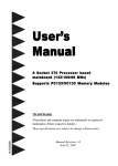
Components Checklist
9
A.
(1)
Mainboard
9
B.
(1)
User’s manual
9
C.
(1)
Floppy ribbon cable
9
D.
(1)
ATA-66/100 Hard drive ribbon cable
9
E.
(1)
USB Cable
9
F.
(1)
Driver and utility
9
G.
(1)
ATA-33 Hard drive ribbon cable
USER’S
MANUAL
C
D
B
G
A
E
or
F
Page 1-1
Introduction
Overview
Terminology
Accelerated Graphics Port (AGP)
The AGP interface that is in the AMD 761TM, it supports a subset of 3.3V, 66MHz
components, 3.3V 66/133 MHz AGP 2.0 compliant components, and the new 1.5V
66/266 MHz components.
Socket A (Socket 462)
The Socket connector that is similar Intel PGA 370 socket. Socket A has 462
pin sites to support AMD DuronTM/AlthonTM processor in PGA package.
3DNow! TM
3DNow! technology enabled fast frame rates on high-resolution 3D rendered
scenes, amazing physical modeling of real-world environments, sharp and
detailed 3D imaging, smooth video playback, and theater-quality audio. The new
enhanced 3DNow! technology implemented in the AMD Athlon processor adds
streaming and digital signal processing (DSP) technologies, which allows faster,
more accurate speech recognition, DVD-quality audio and video, and streaming
audio and video for a rich Internet experience.
DDR SDRAM
The DDR (Double Data Rate) Synchronous SRAM employs high-speed, lowpower CMOS designs. The DDR SRAM enables high performance operation
through high clock frequencies (achieved through pipelining) and double data
rate mode of operation in the system. Double data rate of SDRAM in which data
is sent on both the rising and falling edges of clock cycle in a data burst.
STR (Suspend-To-RAM)
A lower power state than active. In the STR state, the system state is stored in
main memory and all unnecessary system logic is turned off. Only main
memory and logic required to wake the system remain powered.
Page 1-2
Introduction
RAID, RAID 0+1, RAID 0, RAID 1
RAID
Redundant Array of Independent Disks (RAID) refers to a method of
organizing data on one or more physical disks to provide increased
I/O performance and data protection. The different methods for
organizing the data are referred to as RAID Levels. The RAID levels
offered by HPT370A are 0,1 and 0+1.
RAID 0+1 A combination of RAID 1 and RAID 0. Provides high performance
and high availability.
RAID 0
Striping of data across multiple drives in an array. Very fast
performance, however there is no data protection.
RAID 1
Also known as mirroring. Mirroring refers to the 100% duplication
of data from one disk to another. Due to the 100% duplication, this
is a costly solution.
System Overview
The board was developed by AMD-761 system controller (Northbridge) and VIA’s
VT82C686B (Sourthbridge) for the high-performance Socket A AMD DuronTM/
AlthonTM processor-based.
The board is a four-layer, ATX form factor board. That supports a 200/266MHz (double
clocked) front-side bus, 100/133MHz (or 200/266MHz clcok rate) DDR SDRAM interface and supports AGP 2X and 4X, six PCI 32bit/33MHz slots, Suspend-to-RAM, and
paired with VIA VT82C686B Sourthbridge to supports two bus mastering ATA 33/66/
100 EIDE ports. Additionally an extra IDE port by HPT370A/Ultra DMA 66/100 & IDE
RAID x 2 (Up to 4 Device) was supports too (HPT370A is optional). The IDE-RAID
HPT370A supports RAID 0,1 and 0+1. This is idea for small businesses that need to
mirror their servers to used IDE hard disk for a much cheaper solution than SCSI RAID.
The board designs do not contain ISA slots. It supports a “POSTMAN” (optional)
function and “80 Port” to deliver a easy way for the Power On Self Test (POST) code
sending out a error messages via HuMANlike voice by the speaker and POST error
code by the 7-segment LED on board.
Figure 5 Show a block digram for an AMD DuronTM/AlthonTM processor with DDR
SDRAM-base system.
Page 1-3
Introduction
AMD DuronTM & AthlonTM Processors
The AMD AthlonTM is a seventh-generation micro architecture with an integrated
L2 cache, which is powerful enough to support the bandwidth requirements of a
large range of applications, hardware, graphics, and memory technologies. These
processors implement advanced design techniques such as:
Socket A (PGA 462)
200 or 266MHz system interface based on the Alpha™ EV6 bus protocol.
Three out-of-order, superscalar, pipelined Multimedia Units.
Three out-of-order, superscaler, pipelined Integer Units.
Fixed-sized internal instruction formats (MacroOPs).
72-entry Instruction Control Units.
AMD enhanced 3DNow!™ technology
L1 and L2 caches.
Dynamic branch prediction.
Socket A is the name for AMD’s new socketed interface designed to support both
AMD DuronTM and AMD AthlonTM processors. This innovation is made possible
by integrating the L2 cache memory on chip with the processor. Socket A will help
enable smaller enclosures, and ultimately result in a wider variety of solutions in the
market.
The AMD DuronTM & AthlonTM processors in the Socket A format continue to
deliver the ultimate performance for cutting-edge applications. Both bring to
desktop systems running industry-standard x86 software superscalar RISC
performance. Being provided in the Socket A format they are the world’s most
powerful x86 processors. They easily deliver the highest integer, floating-point, and
3D multimedia performance for applications running on x86 platforms around.
The AMD DuronTM processor is derived from the AMD AthlonTM processor core. It
features full-speed, on-chip cache memory, a 200MHz front side system bus, and
enhanced 3DNow!™ technology. Although both processors are related, there are
key differences. The AMD AthlonTM processor is targeted at the performance
segment, and as such will have more cache memory and higher clock speeds.
Page 1-4
Introduction
Accelerated Graphics Port
(AGP or A.G.P.)
Typically, 3D graphics rendering requires a tremendous amount of memory, and
demands ever increasing throughput speed as well. As 3D products for the
personal computer become more and more popular, these demands will only
increase. This will cause a rise in costs for both end users and manufacturers.
Lowering these costs as well as improving performance is the primary motivation
behind AGP. By providing a massive increase in the bandwidth available between
the video card and the processor, it will assist in relieving some of these pressures
for quite sometime.
Ultra ATA/66/100
The board provides two channel (one channel is optional) Ultra ATA/66/100 Bus
Master IDE controller, that support Ultra ATA/66/100 protocols, perfect for such
demanding applications as real-time video, multimedia, and high performance
operating system. A new IDE cable is required for Ultra ATA/66/100. This cable is
an 80 conductor cable; however the connectors are, of course, backwards compatible with ATA/33.
Hardware Monitoring
Hardware monitoring allows you to monitor various aspects of your systems
operations and status. The features include CPU temperature, voltage and RPM of
fan.
Page 1-5
Introduction
Mainboard Form-Factor
The board is designed with ATX form factor - the new industry standard of chassis.
ATX form factor is essentially a Baby-AT baseboard rotated 90 degrees within the
chassis enclosure and a new mounting configuration for the power supply. With
these changes the processor is relocated away from the expansion slots, allowing
them all to hold full length add-in cards. ATX defines a double height aperture to
the rear of the chassis which can be used to host a wide range of onboard I/O.
Only the size and position of this aperture is defined, allowing PC manufacturers
to add new I/O features (e.g.; TV input, TV output, joystick, modem, LAN, etc.) to
systems. This will help systems integrators differentiate their products in the
marketplace, and better meet your needs.
•
Smaller size promotes a smaller system size.
•
I/O shield does not need to be retooled in an ATX 2.01 or later. The
mainboard should be used in an ATX 2.01 (or later) compliant case.
•
A smaller power supply can be used. High integration on mainboard
reduces the system costs.
Expandable I/O
Single chassis
fan for system
ATX
Power
Supply
PCI slots
Floppy / IDE
connectors
close to
peripheral
bays
Page 1-6
CPU located near
Power Supply
ATX power connector
3 1/2"
Bay
5 1/4"
Bay
Figure 2: Summary of ATX chassis features
Introduction
I/O Shield Connector
The board is equipped with an I/O back panel. Please use the appropriate I/O
shield (figure 3).
Joystick/Midi port
parallel port
PS/2 Mouse
USB port
PS/2
KEYBOARD
COM1
COM2
Figure 3: I/O back panel layout
Speaker
Line_in
MIC
Power-On/Off (Remote)
The board has a single 20-pin connector for ATX power supplies. For ATX power
supplies that support the Remote On/Off feature, this should be connected to the
systems front panel for system Power On/Off button. The systems power On/Off
button should be a momentary button that is normally open.
The board has been designed with “Soft Off" functions. You can turn Off the
system from one of two sources: The first is the front panel Power On/Off
button, and the other is the "Soft Off" function (coming from the M/B’s onboard
circuit controller) that can be controlled by the operating system such as Windows®
95/98/SE/ME or Windows®2000.
ATX
POWER SUPPLY
J3
Case (chassis) Power
ON/OFF button (J 3)
Figure 4: Simple ATX Power ON/OFF Controller
Page 1-7
Introduction
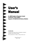
System Block Diagram
AMD
Socket A
Processors
133/100MHz
4X
66MHz
PAC
PCI Bridge
and memory
controller
AMD761
DDR SDRAM
266/200MHz
HPT370A
ATA100
With RAID
(Optional)
UIDE 1
UIDE 2
(Optional)
AC
97
POST
MAN
VT82C686B
I/O Bridge
IDE 1
IDE 2
80 Port
USB 0,1
USB 2,3
Figure 5: System Block Diagram
Page 1-8
HDD
(ATA-66/100)
Features
Section 2
FEATURES
Mainboard Features:
PROCESSOR
TM
TM
- AMD Athlon , Duron Processors with a 200/266 MHz Host bus (100/
133MHz x 2), Socket A, operating at 600MHz ~ 1.2GHz
CHIPSET
- AMD-760
TM
Chipset (AMD-761
TM
+ VIA VT82C686B)
DDR SDRAM DIMM MODULE
- 184pin DDR DIMM x 2 for PC1600/2100 Memory
- DRAM Size: 64MB to 512MB
EXPANSION SLOT
- PCI x 6 (six PCI bus master), 4X AGP x 1
ONBOARD I/O
- On-Chip I/O integrated with K/B, Mouse, FDD, Parallel and Serial, Fast
IR and Power-ON controllers
ONBOARD PCI / IDE
- PCI Bus IDE Port with PIO / Ultra DMA-66/100 x 2 (Up to 4 Devices)
Extra IDE Port by HPT370A with Ultra DMA 66/100 & IDE RAID x 2 (Up to
4 Devices)(Optional)
I/O CONNECTOR
- PS/2 Mouse and PS/2 style Keyboard
USB
- USB connector x 4 (2 for Opt.)
Page 2-1
Features
BIOS
- Award Plug & Play BIOS
Built-in AC97 Digital Audio(by VT82C686B)
- Dual full-duplex Direct Sound channels
- H/W Sound Blaster Pro for DOS legacy compatibility
- FM synthesis for legacy compatibility
- Supports game and MIDI port
EXTENDED FUNCTION
- Supports exclusive USDM (Unified System Diagnostic Manager) and
Hardware Monitoring Function by VT82C686B
- Supports exclusive KBPO (KeyBoard Power On)
- Supports Wake-On-LAN Function
- Supports Wake-On-Modem Function
- Supports STR (Suspend To Ram) function
- Supports CPU Vcore & DDR Voltage settings via Jumper
- Supports CPU Clock & Multiplier settings via BIOS & Jumper
- 80 Port Debug(POST) Card onboard design with 7-segment LED display
- Supports POSTMAN(Power On Self Test with Human-like voice alarm)
(Optional)
FORM FACTOR
- 305mm x 245mm ATX Size
Page 2-2
Installation
Section 3
INSTALLATION
Page 3-1
Installation
Mainboard Detailed Layout
Figure 1
Page 3-2
Installation
Easy Installation Procedure
The following must be completed before powering on your new system:
3-1.
3-2.
3-3.
3-4.
3-5.
3-6.
3-7.
CPU Insertion
Jumper Settings
System memory Configuration
Device Connectors
External Modem Ring-in Power ON and Keyboard Power ON
Functions (KBPO)
STR Function (STR function is applicable to the ports of IDE1 and IDE2)
POSTMAN Function
Section 3-1
CPU Insertion
CPU Insertion: (use AMD AthlonTM as reference)
Step 1
Open the socket by raising the actuation
lever.
Figure 2
Step 2
Insert the processor.
Figure 3
Ensure proper pin 1 orientation by aligning
the FC-PGA corner marking with the
socket corner closest to the actuation arm
tip. The pin field is keyed to prevent misoriented insertion.
Don’t force processor into socket. If it does
not go in easily, check for mis-orientation
and debris. Make sure the processor is fully
inserted into the socket on all sides.
Page 3-3
Installation
Step 3
Close the socket by lowering and
locking the actuation lever.
Figure 4
Step 4
Thermal compound and qualified heatsink recommended by AMD are a must to
avoid CPU overheat damage. For more information about installing your CPU,
please refer to the AMD website article “Socket A AMD processor and Heatsink
Installation Guide” http://www.amd.com/products/cpg/athlon/pdf/23986.pdf.
Figure 5
Page 3-4
Installation
Section 3-2
Jumper Settings
SW2: CPU Ratio Selection
SW2
1
ON
1 23 45
2
3
4
5
CPU Ratio
X
X
X
X
OFF
ON
ON
ON
ON
ON
AUTO (Default)
x 11
OFF
ON
ON
ON
ON
x 11.5
ON
OFF
ON
ON
ON
x 12
OFF
OFF
ON
ON
ON
x 12.5
ON
ON
OFF
ON
ON
x5
OFF
ON
OFF
ON
ON
x 5.5
ON
OFF
OFF
ON
ON
x6
OFF
OFF
OFF
ON
ON
x 6.5
ON
ON
ON
OFF
ON
x7
OFF
ON
ON
OFF
ON
x 7.5
ON
OFF
ON
OFF
ON
x8
OFF
OFF
ON
OFF
ON
x 8.5
ON
ON
OFF
OFF
ON
x9
OFF
ON
OFF
OFF
ON
x 9.5
ON
OFF
OFF
OFF
ON
x 10
OFF
OFF
OFF
OFF
ON
x 10.5
X: don’t care
JP1
1
CMOS Clear
1-2 Normal (Default)
2-3 Clear CMOS
Page 3-5
Installation
JP2
1
6
CPU Vcore Adjust
JP3
JP 2
CPU Vcore Adjust
1-6
+0.V (Default)
2-7
+0.1V
3-8
+0.2V
4-9
+0.3V
5-10
+0.4V
6
1
DDR Adjust (2.5V)
JP 3
DDR Adjust (2.5V)
1-6
+0.0V
2-7
+0.1V (Default)
3-8
+0.2V
4-9
+0.3V
5-10
+0.4V
JCLK1
1
CPU Clock Select
JC L K 1
Page 3-6
AGP
PC I
1-2 (Default)
100MHz 200MHz
C PU
DDR
66.6
33.3
2-3
133MHz 266MHz
66.6
33.3
Installation
JP5
1
Power Loss Recovery
1-2 Disabled (Default)
2-3 Enabled
JP13
1
Keyboard Power On Function
1-2 Disabled (Default)
2-3 Enabled
Page 3-7
Installation
Section 3-3
System Memory Configuration
Memory Layout
The board supports (2) PC1600/2100 184-pin DIMMs (Dual In-line Memory Module).
The DIMMs is for DDR SDRAM (Double-Data-Rate Synchronous DRAM) only.
•
DDR SDRAM support 200MHz at AMD AthlonTM/DuronTM 100MHz frontside bus or 266MHz at AMD AthlonTM/DuronTM 133MHz front-side bus.
•
Supports Memory Error Correcting Code (ECC).
•
Supports 64Mbit, 128Mbit, 256Mbit and 512Mbit technology.
•
64-bit data width, plus & 8 bit ECC paths.
•
Supports up to two unbuffered DDR DIMMs or two registered DIMMs.
•
Supports up to 1Gbytes of memory.
Figure 6 and Table 1 show several possible memory configurations.
DDR DIMM 1
Bank 0/1
DDR DIMM 2
Bank 2/3
DDR
Synchronous
DRAM
Figure 6
Total M e mory
DDR DIM M 1
(Bank 0/1)
DDR DIM M 2
(Bank 2/3)
= 512MB
Maximum
DDR SDRAM*
64MB, 128MB, 256MB,
512MB X 1
None
= 1GB
Maximum
DDR SDRAM*
64MB, 128MB, 256MB,
512MB X 1
DDR SDRAM*
64MB, 128MB, 256MB,
512MB X 1
Table 1
* DDR SDRAM supports 64, 128, 256, 512MB DIMM modules.
* We recommend using PC1600 Memory Module only for front-side bus
100MHz.
* DO NOT MIX the unbuffered and registered DDR SDRAM on DIMM1
and DIMM2 socket.
* Supports PC1600 modules with 2-2-2 timing.
* Supports PC2100 modules with 2-2-2 timing.
Page 3-8
Installation
DIMM Module Installation
Figure 7 displays the notch marks and what they should look like on your DDR
DIMM memory module.
DIMMs have 168-pins and one notche that will match with the onboard DDR
DIMM socket. DIMM modules are installed by placing the chip firmly into the
socket at a 90 degree angle and pressing straight down (figure 8) until it fits tightly
into the DIMM socket (figure 9).
CENTER KEY ZONE
(2.5 V DRAM)
Figure 7
Figure 8
DIMM Module clip before installation
Figure 9
DIMM Module clip after installation
To remove the DIMM module simply press down both of the white clips on either
side and the module will be released from the socket.
Page 3-9
Installation
Section 3-4
Device Connectors
parallel port
PS/2 Mouse
Joystick/Midi port
USB port
PS/2
KEYBOARD
COM1
COM2
Figure 10
Speaker
Line_in
MIC
J2,J3:
Chassis Panel Connector
• Power_LED, Speaker, Reset, Power ON/Off, Turbo LED, HDD LED,
IR Conn.,
J4:
CPU Fan Power
• A plug-in for the CPU Fan Power
J5:
Power Fan Power
• A plug-in for the Power Supply Fan Power
J6:
Chassis Fan Power
• A plug-in for the chassis Fan Power
J7:
WOL (Wake On Lan) Connector
J8:
WOM (Wake On Modem) Connector
IDE1:
Ultra ATA-66/100 Primary IDE Connector (supported by 686B chipset)
(Blue Color)
IDE2:
Ultra ATA-66/100 Secondary IDE Connector (supported by 686B chipset)
(Blue Color)
UIDE1: Ultra ATA-66/100&RAID Primary IDE Connector (supported by HPT370A
chipset) (Blue Color)(Optional)
UIDE2: Ultra ATA-66/100&RAID Secondary IDE Connector (supported by HPT370A
chipset) (Blue Color)(Optional)
Page 3-10
Installation
FDD1: Floppy Controller Connector (Black Color)
PW1: ATX Power Connector
• 20-pin power connector
CD1:
CD Audio_IN Connector
• Pin1(CD_IN_Left), Pin2/Pin3(CD_Reference), Pin4(CD_IN_Right)
AUX1: Auxiliary Line_IN Connector
• Pin1(Left Line_IN), Pin2/Pin3(GND), Pin4(Right Line-IN)
MODEM1:
Telephony Connector for Modem audio output
• Pin1(Audio_in), Pin2/Pin3(GND), Pin4(Mic-out to Modem)
USB2: USB port header pins for adding two additional USB ports.
1
6
VCC
GND
-Data
+Data
+Data
-Data
GND
VCC
5
10
USB port header pin descriptions.
PIN#
Wire color
Signal Name
Comment
1
Red
Vcc
Cable Power
2
White
-Data
Data
3
Green
+Data
Data
4
Black
Ground
Cable Ground
5
Black
Ground
Case Ground
6
Black
Ground
Case Ground
7
Black
Ground
Cable Ground
8
Green
+Data
Data
9
White
-Data
Data
10
Red
Vcc
Cable Power
Page 3-11
Installation
Device Connectors (continued)
(This is connected to the power button on the case. Using the Soft-Off
by Pwr-BTTN feature, you can choose either Instant Off (turns system
off immediately), or 4 sec delay (you need to push the button down for
4 seconds before the system turns off). When the system is in 4 sec
delay mode, suspend mode is enabled by pushing the button
momentarily.)
Power On/Off
J3
1
Turbo LED indicator - LED ON when higher speed is selected
+
IDE LED indicator - LED ON when Onboard PCI IDE Hard disks is
activate
+
IR Connector
1. VCC
2. NC
3. IRRX
4. GND
5. IRTX
1
J2
Power LED - Power LED and S3 LED connector
1. Power LED(+)
2. N/C
3. GND
4. NC
5. GND
1
Speaker - Connect to the system's speaker for beeping
1. Speaker
2. N/C
3. GND
4. GND
1
Reset - Closed to restart system.
1
Page 3-12
Installation
Section 3-5
External Modem Ring-in Power
ON and Keyboard Power ON
Functions (KBPO)
On the basis of bounded functions in I/O chipset, the two serial ports are able to
support the External Modem Ring-in Power ON function. Once users connect the
external modem to COM1 or COM2, the mainboard allows users to turn on their
system through the remote and host's dial-up control.
Exclusive Keyboard Power ON Function
To innovate a unique feature to benefit users, we devoted the easiest and most
convenient way to turn on your system based on the the ATX power supply.
How to work with it
Step 1: Please check JP13 at the position 2-3 after you finished the system
installation.
JP13
1
Keyboard Power On Function
1-2 Disabled (Default)
2-3 Enabled
Step 2: Push the momentary switch (J3 PW-ON) to turn on your system and then
push again to hold for more than 4 seconds to turn it off affter counting
memory as soon as you turn it on.
Step 3: You can enjoy the Keyboard Power ON function (KBPO) by pressing any
key to turn on your system. Your system will be turned on automatically,
after releasing the keys. To power off you system, you can use the SoftOFF function under Windows® 95/98 or Windows®2000.
Page 3-13
Installation
Notes:
1. Intel ATX version 2.0 specification recommended you use the power supply
with >=1.0A in 5.0VSB. With our mainboard, the 5.0VSB standby power only
has to be > = 0.1A (100mA) then you can enjoy this unique benefit. However,
an ATX power supply which is < 0.1A (100mA) is still useable to your system
by placed JP13 at the position 1-2 to disable this feature.
2. We recommended you use the power supply with 1.0A in 5.0VSB. Because this
supported PCI 2.1 specification for remote power-on and wake-up function.
Page 3-14
Installation
3-6 STR (Suspend To RAM) Function
The board supports the STR power management state by maintaining the
appropriate states on the DDR SDRAM interface signals. The power source
must be kept alive to the DDR SDRAM during STR (ACPI S3). Advanced
Configuration Power Interface (ACPI) provides more Energy Saving Features
for operating systems that supporting Instant ON and QuickStartTM function.
1. To enable the ACPI function and use the STR functionally to save your system
energy, you are recommended to confirm the following requirements:
a. Please do install all ACPI qualified add-on cards such as AGP, LAN,
Modem cards.
b. In BIOS, please select “ ACPI function: Enable” and “ACPI Suspend Type:
S3(STR)” in the Power Management Setup menu.
c. Then, please install the Windows® 98SE/ME or Windows® 2000.
d. Restart your system.
e. Getting in to the “Advanced” of the Power Management icon of Control
Panel, and selecting the “Stand By” in the Power Buttons.
2. Getting start with STR function, please click the START button and choose
Shut Down. Then, select the Stand By option in the Shut Down Windows box
to get into STR mode.
Here are the differences between STR power saving mode and Green (or
Suspend) mode:
a. It is the most advanced Power Management mode
b. It cuts all the power supplied to peripherals except to Memory - max.
power saving
c. It saves and keeps all on-screen data including any executed applications to
DDR SDRAM.
d. You must push the Power button connected with onboard J3 pin to wake up
you system (not to click to mouse or press keyboard to wake up the
system).
Page 3-15
Installation
Just pushing Power button, your system will quickly back to the last screen for
you.
The “LED Indicator for ACPI Status” table shown below will guide you and give
you a reference for ACPI status on this mainboard.
ACPI Onboard’s LED Status Indicator Table
Onboard’s
LED
Location
Status
Plug in the ATX
Power Core
Power ON
J3(PW-ON)
Green Mode
(S1)
STR
(S3)
Shutdown
(Soft-OFF)
(S5)
LED1
(Red LED)
OFF
ON
ON
ON
OFF
J2
PW_LED
OFF
ON
Blinking
Blinking
OFF
Page 3-16
Installation
3-7 “POSTMAN
POSTMAN” Function Introduction (Optional)
POSTMAN
With the board also make our initial premier of the new “POSTMAN” debug
function. This new feature designed to enhance the Power On Self Test (POST)
introduces a huMANlike voice with helpful debugging/error messages. So in the
event the system experiences boot up difficulties “POSTMAN” will deliver the
message in an easier to understand method than traditional POSTcodes. Such as,
“SDRAM Detect Fail” for memory missing, memory install improperly or
memory broken and “VGA Fail” for AGP card missing, AGP card install improperly or AGP card broken.
The voice could be pronounced through either an internal speaker or external
speakers plugged into Line Out connector for a clear sound.
The messages recorded for this function are listed below for your reference
while having problems with system boot up.
0.
SDRAM Detect Fail
1.
BIOS ROM Checksum Fail
2.
Keyboard or PS/2 Mouse Fail
3.
VGA Fail
4.
Clock Generator or Overclock Fail
5.
NO CPU Fan
6.
Over Voltage Fail
7.
SMBUS Fail
8.
System boot OK
9.
CPU, BIOS or Power Cable plug in abnormal
Page 3-17
Installation
Page Left Blank
Page 3-18
BIOS
Section 4
BIOS SETUP
Main Menu
Once you enter the AwardBIOS™ CMOS Setup Utility, the Main Menu will appear
on the screen. The Main Menu allows you to select from several setup functions and
two exit choices. Use the arrow keys to select among the items and press <Enter>
to accept and enter the sub-menu.
Note that a brief description of each highlighted selection appears at the bottom of
the screen.
Setup Items
The main menu includes the following main setup categories. Recall that some
systems may not include all entries.
Standard CMOS Features
Use this menu for basic system configuration.
Page 4-1
BIOS
Advanced BIOS Features
Use this menu to set the Advanced Features available on your system.
Advanced Chipset Features
Use this menu to change the values in the chipset registers and optimize your
system’s performance.
Integrated Peripherals
Use this menu to specify your settings for integrated peripherals.
Power Management Setup
Use this menu to specify your settings for power management.
PnP / PCI Configuration
This entry appears if your system supports PnP / PCI.
PC Health Status
This item is only show the system health status (include Voltage, Fan speed, CPU
temperature...)
Frequency/Voltage Control
Use this menu to specify your settings for frequency/voltage control.
Load Fail-Safe Defaults
Use this menu to load the BIOS default values for the minimal/stable performance for your system to operate.
Load Optimized Defaults
Use this menu to load the BIOS default values that are factory settings for optimal performance system operations. While Award has designed the custom BIOS
to maximize performance, the factory has the right to change these defaults to
meet their needs.
Supervisor / User Password
Use this menu to set User and Supervisor Passwords.
Save & Exit Setup
Save CMOS value changes to CMOS and exit setup.
Exit Without Save
Abandon all CMOS value changes and exit setup.
Page 4-2
BIOS
4-1 Standard CMOS Setup
The items in Standard CMOS Setup Menu are divided into 10 categories. Each category includes no, one or more than one setup items. Use the arrow keys to highlight the item and then use the <PgUp> or <PgDn> keys to select the value you want
in each item.
Figure 1: The Main Menu
Page 4-3
BIOS
Main Menu Selections
This table shows the selections that you can make on the Main Menu
Item
Options
Month
Time
HH : MM : SS
Options are in its sub menu
(described in Table 3)
Options are in its sub menu
(described in Table 3)
Options are in its sub menu
(described in Table 3)
Options are in its sub menu
(described in Table 3)
None
360K, 5.25 in
1.2M, 5.25 in
720K, 3.5 in
1.44M, 3.5 in
2.88M, 3.5 in
EGA/VGA
CGA 40
CGA 80
MONO
All Errors
No Errors
All, but Keyboard
All, but Diskette
All, but Disk/Key
IDE Primary Master
IDE Primary Slave
IDE Secondary Master
IDE Secondary Slave
Drive A
Drive B
Video
Halt On
DD
Description
Date
Base Memory
N/A
Extended Memory
N/A
Total Memory
N/A
YYYY
Set the system date. Note that
the ‘Day’ automatically hanges
when you set the date
Set the system time
Press <Enter> to enter the sub
menu of detailed options
Press <Enter> to enter the sub
menu of detailed options
Press <Enter> to enter the sub
menu of detailed options
Press <Enter> to enter the sub
menu of detailed options
Select the type of floppy disk
drive installed in your system
Select the default video device
Select the situation in which
you want the BIOS to stop the
POST process and notify you
Displays the amount of
conventional memory detected
during boot up
Displays the amount of
extended memory detected
during boot up
Displays the total memory
available in the system
Table 2 Main Menu Selections
Page 4-4
BIOS
IDE Adapters
The IDE adapters control the hard disk drive. Use a separate sub menu to configure
each hard disk drive.
Figure 2 shows the IDE primary master sub menu.
[
[
[
]
]
]
Figure 2 IDE Primary Master sub menu
Page 4-5
BIOS
Use the legend keys to navigate through this menu and exit to the main menu. Use
Table 3 to configure the hard disk.
Item
Options
Description
IIDE HDD Auto-detection
Press Enter
IDE Primary Master
None
Auto
Manual
Capacity
Auto Display your disk
drive size
Press Enter to auto-detect the HDD
on this channel. If detection is
successful, it fills the remaining
fields on this menu.
Selecting ‘manual’ lets you set the
remaining fields on this screen.
Selects the type of fixed disk. "User
Type" will let you select the number
of cylinders, heads, etc.
Note: PRECOMP=65535 means
NONE !
Disk drive capacity
(Approximated). Note that this
size is usually slightly greater than
the size of a formatted disk given by
a disk checking program.
Choose the access mode for this
hard disk
Access Mode
Normal
LBA
Large
Auto
The following options are selectable only if the ‘IDE Primary Master’ item is set to ‘Manual’
Cylinder
Head
Precomp
Landing zone
Sector
Min = 0
Max = 65535
Min = 0
Max = 255
Min = 0
Max = 65535
Min = 0
Max = 65535
Min = 0
Max = 255
Set the number of cylinders for this
hard disk.
Set the number of read/write heads
**** Warning: Setting a value of
65535 means no hard disk
****
Number of sectors per track
Table 3 Hard disk selections
Page 4-6
BIOS
4-2 Advanced BIOS Features
This section allows you to configure your system for basic operation. You have the
opportunity to select the system’s default speed, boot-up sequence, keyboard
operation, shadowing and security.
Virus Warning
Allows you to choose the VIRUS Warning feature for IDE Hard Disk boot sector
protection. If this function is enabled and someone attempt to write data into this
area, BIOS will show a warning message on screen and alarm beep.
Enabled: Activates automatically when the system boots up causing a warning
message to appear when anything attempts to access the boot sector
or hard disk partition table.
Disabled: No warning message will appear when anything attempts to access the
boot sector or hard disk partition table.
CPU Internal Cache/External Cache
These two categories speed up memory access. However, it depends on CPU/chipset
design.
The choice: Enabled/Disabled.
Page 4-7
BIOS
Quick Power On Self Test
This category speeds up Power On Self Test (POST) after you power up the computer.
If it is set to Enable, BIOS will shorten or skip some check items during POST.
Enabled: Enable quick POST
Disabled: Normal POST
HPT-370 or SCSI Card Boot
Setup the boot up priority either from onboard HPT-370 connector or SCSI Card, if you
select SCSI as the first boot device at the option below.
First/Second/Third/Other Boot Device
The BIOS attempts to load the operating system from the devices in the sequence
selected in these items.
The Choice: Floppy, LS120, HDD-0, SCSI, CDROM, HDD-1, HDD-2, HDD-3,
ZIP100, LAN, Disabled.
Swap Floppy Drive
If the system has two floppy drives, you can swap the logical drive name assignments.
The choice: Enabled/Disabled.
Boot Up Floppy Seek
Seeks disk drives during boot up. Disabling speeds boot up.
The choice: Enabled/Disabled.
Boot Up NumLock Status
Select power on state for NumLock.
The choice: On/Off.
Typematic Rate Setting
Key strokes repeat at a rate determined by the keyboard controller. When enabled,
the typematic rate and typematic delay can be selected.
The choice: Enabled/Disabled.
Typematic Rate (Chars/Sec)
Sets the number of times a second to repeat a key stroke when you hold the key
down.
The choice: 6, 8, 10, 12, 15, 20, 24, 30.
Page 4-8
BIOS
Typematic Delay (Msec)
Sets the delay time after the key is held down before it begins to repeat the keystroke.
The choice: 250, 500, 750, 1000.
Security Option
Select whether the password is required every time the system boots or only when you
enter setup.
System The system will not boot and access to Setup will be denied if the
correct password is not entered at the prompt.
Setup
The system will boot, but access to Setup will be denied if the
correct password is not entered at the prompt.
Note: To disable security, select PASSWORD SETTING at Main Menu and
then you will be asked to enter password. Do not type anything and
just press <Enter>, it will disable security. Once the security is
disabled, the system will boot and you can enter Setup freely.
OS Select For DRAM > 64MB
Select the operating system that is running with greater than 64MB of RAM on the
system. The choice: Non-OS2, OS2.
Video BIOS Shadow
This option allows video BIOS to be copied into RAM. Video Shadowing will
increase the video performance of your system.
The default is Enabled.
The choice: Enabled/Disabled.
Page 4-9
BIOS
4-3 Advanced Chipset Features
This section allows you to configure the system based on the specific features of
the installed chipset. This chipset manages bus speeds and access to system
memory resources, such as DRAM and the external cache. It also coordinates
communications between the conventional ISA bus and the PCI bus. It must be
stated that these items should never need to be altered. The default settings have
been chosen because they provide the best operating conditions for your system.
The only time you might consider making any changes would be if you discovered
that data was being lost while using your system.
System Performance
This item will help you to configure your system performance quickly and easily.
There are two selections. When a selection is mode , the other related items will
automatically vary values.
The Choice: Normal, Fast.
Note: If you select the higher performance, compatibility problem could be
occurred.
Page 4-10
BIOS
System BIOS Cacheable
Selecting Enabled allows caching of the system BIOS ROM at F0000h-FFFFFh,
resulting in better system performance. However, if any program writes to this
memory area, a system error may result.
The choice: Enabled, Disabled.
Video RAM Cacheable
This option allows the CPU to cache read/writes of the video RAM. The default is
Disabled
Enabled: This option allows for faster video access.
Disabled: Reduced video performance.
Memory Hole At 15M-16M
You can reserve this area of system memory for ISA adapter ROM. When this area
is reserved, it cannot be cached. The user information of peripherals that need to use
this area of system memory usually discusses their memory requirements.
The Choice: Enabled, Disabled.
AGP Graphics Aperture Size (MB)
The amount of system memory that the AGP card is allowed to share. The default
is 128.
32: 32MB of systems memory accessable by the AGP card.
64: 64MB of systems memory accessable by the AGP card.
128: 128MB of systems memory accessable by the AGP card.
256: 256MB of systems memory accessable by the AGP card.
AGP ISA Aliasing
You can reserve this item for more compatibility with ISA VGA.
The Choice: Enabled, Disabled.
AGP Secondary Lat Timer
Adhere to definition of the latency timer in the PCI Local Bus Specification,
Revision 2.2 but only applies to the secondary interface of a PCI-to PCI bridge.
The Choice: 00h, 20h, 40h, 60h, 80h, C0h, FFh.
AGP Fast Write
Select Enabled allows to use Fast Write Protocol for 4X AGP.
The Choice: Enabled, Disabled.
Page 4-11
BIOS
AGP Data transfer Mode
Chipset AGP Mode support
The Choice: 1x/2x, 4x
AGP Always Compensate
When Enable dynamic compensation is performance by AGP on an ongoing basis at
regular intervals this will make more comptibility with AGP VGA.
The Choice: Enabled, Disabled.
SDRAM ECC Setting
Use this option to configurate the type of DRAM in your system.
The Choice: Disabled, Check Only, Correct Errors, Correct+Scrub.
Super Bypass Mode
When Enable the AMD-761 system controller internally bypasses certain memory
pipe stages for optional performance.
The Choice: Enabled, Disabled.
SDRAM Timing Setting By
For setting DRAM timing, By Auto is follow Intel PC SDRAM Serial Presence
Detect Specification.
The Choice: Auto, Manual.
SDRAM PH Limit
This item control the number of consecutive page hit request to allow before
choosing a non-PH request.
The Choice: 1, 4, 8, 16 cycle.
SDRAM Idle Limit
This item control the number of idle cycle to wait before precharging on idle bank.
The Choice: 0, 8, 12, 16, 24, 32, 48 cycle.
SDRAM Trc Timing Value
This item indicates the Trc timing value (bank cycle time: minimum time from
activate to activate of same bank).
The Choice: 3, 4, 5, 6, 7, 8, 9, 10 cycle.
Page 4-12
BIOS
SDRAM Trp Timing Value
This item indicates the Trp timing value (precharge time: time from precharge to
activate on the same bank).
The Choice: 3, 2, 1, 4 cycle.
SDRAM Tras Timing Value
This item indicates the Tras timing value (minimum bank active time: time from
activate to precharge on the same bank).
The Choice: 2, 3, 4, 5, 6, 7, 8, 9 cycle.
SDRAM CAS Latency
When synchronous DRAM is installed, the number of clock cycles of CAS latency
depends on the DRAM timing.
The Choice: 2, 2.5 cycle.
SDRAM Trcd Timing Value
This item indicates the Trcd timing value (RAS to CAS latency delay from activate
to RD/WR command).
The Choice: 2, 3, 4, 5, 6, 7, 8, 9 cycle.
Page 4-13
BIOS
4-4 Integrated Peripherals
OnChip Primary/Secondary PCI IDE
The integrated peripheral controller contains an IDE interface with support for two
IDE channels. Select Enabled to activate each channel separately.
The choice: Enabled, Disabled.
IDE Prefetch Mode
Enable prefetching for IDE drive interfaces that support its faster drive accesses.
If you are getting disk drive errors, change the setting to omit the drive interface
where the errors occur. Depending on the configuration
of your IDE subsystem, this field may not appear, and it does not appear when the
Internal PCI/IDE field, above, is Disabled.
The Choice: Enabled, Disabled.
Primary/Secondary Master/Slave PIO
The four IDE PIO (Programmed Input/Output) fields let you set a PIO mode (0-4)
for each of the four IDE devices that the onboard IDE interface supports. Modes 0
through 4 provide successively increased performance. In Auto mode, the system
automatically determines the best mode for each device.
The choice: Auto, Mode 0, Mode 1, Mode 2, Mode 3, Mode 4.
Page 4-14
BIOS
Primary/Secondary Master/Slave UDMA
Ultra DMA/33 implementation is possible only if your IDE hard drive supports it
and the operating environment includes a DMA driver (Windows 95 OSR2 or a thirdparty IDE bus master driver). If your hard drive and your system software both support Ultra DMA/33, select Auto to enable BIOS support.
The Choice: Auto, Disabled.
Init Display First
This item allows you to decide to active whether PCI Slot or on-chip VGA first
The choice: PCI Slot, Onboard .
Onboard High Point 370
This item can control on board PCI device High Point 370 to enable or disable.
The Choice: Enabled, Disabled.
Flash R/W Control
The Choice: Enabled, Disabled.
OnChip USB1/2
This should be enabled if your system has a USB installed on the system board and
you want to use it. Even when so equipped, if you add a higher performance controller,
you will need to disable this feature.
The choice: Enabled, Disabled.
USB Keyboard/Mouse Support
Select Enabled if your system contains a Universal Serial Bus (USB) controller and
you have a USB Legacy Device (Keyboard, Mouse).
The choice: Enabled, Disabled.
AC97 Audio
This item allows you to decide to Auto or disable the chipset family to support
AC97 Audio.
The function setting AC97 Audio Codec states. The system default is Auto.
IDE HDD Block Mode
Block mode is also called block transfer, multiple commands, or multiple sector
read/write. If your IDE hard drive supports block mode (most new drives do), select
Enabled for automatic detection of the optimal number of block read/writes per
Page 4-15
BIOS
sector the drive can support.
The choice: Enabled, Disabled
Onboard FDD Controller
Select Enabled if your system has a floppy disk controller (FDC) installed on the
system board and you wish to use it. If you install and-in FDC or the system has no
floppy drive, select Disabled in this field.
The choice: Enabled, Disabled.
Onboard Serial Port 1/Port 2
Select an address and corresponding interrupt for the first and second serial ports.
The choice: 3F8/IRQ4, 2E8/IRQ3, 3E8/IRQ4, 2F8/IRQ3, Disabled.
UART 2 Mode
This filed allows the users to configure what IR mode the 2nd serial port should use.
The default is Stardand.
Optional: Stardand, HPSIR and ASKIR.
Onboard Parallel port
This field allows the user to configure the LPT port.
The default is 378H / IRQ7.
378H: Enable Onboard LPT port and address is 378H and IRQ7.
278H: Enable Onboard LPT port and address is 278H and IRQ5.
3BCH: Enable Onboard LPT port and address is 3BCH and IRQ7.
Disabled: Disable Onboard LPT port.
Parallel Port Mode
This field allows the user to select the parallel port mode.
The default is EPP+ECP.
Normal: Standard mode. IBM PC/AT Compatible bidirectional parallel port.
EPP: Enhanced Parallel Port mode.
ECP: Extended Capabilities Port mode.
EPP+ECP: ECP Mode & EPP Mode.
ECP Mode USE DMA
This field allows the user to select DMA1 or DMA3 for the ECP mode.
The default is DMA3.
Page 4-16
BIOS
DMA1:
This field selects the routing of DMA1 for the ECP mode.
DMA3:
This field selects the routing of DMA3 for the ECP mode.
Parallel Port EPP Type
This item allows you to determine the IR transfer mode of onboard I/O chip.
options: EPP1.9, EPP1.7.
Onboard Legacy Audio
Legacy Audio enabled/disabled.
Sound Blaster
Sound Blaster compatible device enabled/disabled.
SB I/O Base Address
Sound Blaster I/O resource selection.
SB IRQ Select
Legacy audio device IRQ selection.
SB DMA Select
Sound Blaster DMA channel selection.
MPU-401
MPU-401 function enabled/disabled.
MPU-401 I/O Address
Built-in MPU-401 compatible MIDI I/O port selection:
The Choice: 300-303H, 310-313H, 320-323H, 330-333H (default)
Game Port (200-207H)
Built-in joystick port support disabled/enabled(default).
Page 4-17
BIOS
4-5 Power Management Setup
The Power Management Setup allows you to configure you system to most effectively save energy while operating in a manner consistent with your own style of
computer use.
ACPI Function
This item allows you to enable/disable the Advanced Configuration and Power Management (ACPI).
The choice: Enabled, Disabled.
ACPI Suspend Type
This item allows you to select S1(POS) or S3(STR) function.
The choice: S1(POS), S3(STR).
Power Management
This category allows you to select the type (or degree) of power saving and is directly related to the following modes:
1. HDD Power Down
2. Doze Mode
3. Suspend Mode
Page 4-18
BIOS
There are four selections for Power Management, three of which have fixed mode
settings.
Disable (default)
Min. Power Saving
Max. Power Saving
User Defined
No power management. Disables all four modes
Minimum power management. Doze Mode = 1
hr. Standby Mode = 1 hr., Suspend Mode = 1 hr.,
and HDD Power Down = 15 min.
Maximum power management -- ONLY
AVAILABLE FOR SL CPU’s. Doze Mode = 1
min., Standby Mode = 1 min., Suspend Mode = 1
min., and HDD Power Down = 1 min.
Allows you to set each mode individually. When
not disabled, each of the ranges are from 1 min. to
1 hr. except for HDD Power Down which ranges
from 1 min. to 15 min. and disable.
Video Off Method
This determines the manner in which the monitor is blanked.
V/H SYNC+Blank
Blank Screen
DPMS
This selection will cause the system to turn off the
vertical and horizontal synchronization ports and
write blanks to the video buffer.
This option only writes blanks to the video buffer.
Initial display power management signaling.
Standby Mode
When the standby mode timer times-out, it will enter the standby mode and retain
CPU at a slow working speed. The screen will be blanked out.
The choice: Disabled, 30sec, 1min, 4min, 20min, 30min, 1 hour.
HDD Power Down
When enabled and after the set time of system inactivity, the hard disk drive will be
powered down while all other devices remain active.
The choice: Enabled, Disabled.
HDD Down In Suspend
The choice: Enabled, Disabled.
Soft-Off by PWR-BTTN
Pressing the power button for more than 4 seconds forces the system to enter the
Soft-Off state when the system has “hung.” The default is Instant-off.
The choice: Delay 4 Sec, Instant-Off.
Page 4-19
BIOS
PWRON After PW-Fail
The system will stay of or power on after a power interrupte.
The default is OFF.
Fomer-Status: Stay off or power on depend on system safe shut-down or
power fail.
ON:
System always power on after a power interrupte.
OFF:
System always stay off after a power interrupte.
Wake-UP by PCI Card (PME)
An input signal from PME on the PCI card awakens the system from a soft off state.
The choice: Enabled, Disabled.
PS/2 Keyboard POWER ON
This item allows you to select wake-up the system by PS2 Keyboard when you
save the computer power at S1-S5 mode.
The choice: Enabled, Disabled.
Wake Up by Modem & LAN
When set to Enabled, any event occurring to the Modem ring / LAN will awaken a
system which has been powered down.
The choice: Enabled, Disabled.
MODEM Use IRQ
The determine the IRQ in which the MODEM can use.
The choice: 3, 4, 5, 7, 9, 10, 11, NA.
RTC Resume
This option allows you to have the system turn on at a present time each day or on a
certain day.
The choice: Disabled, Enabled.
IRQ Wakeup Events
Allows users to set system to monitor IRQs 3-15 for activity to awaken system
form a power management mode.
VGA
When set to On (default), any event occurring at a VGA port will awaken a system
which has been powered down.
Page 4-20
BIOS
LPT & COM
When set to On (default), any event occurring at a COM(serial)/LPT (printer) port
will awaken a system which has been powered down.
HDD & FDD
When set to On (default), any event occurring at a hard or floppy drive port will
awaken a system which has been powered down.
PCI master
When set to On (default), any event occurring to the DMA controller will awaken a
system which has been powered down.
Page 4-21
BIOS
4-6 PnP/PCI Configuration Setup
This section describes configuring the PCI bus system. PCI, or Personal Computer
Interconnect, is a system which allows I/O devices to operate at speeds nearing the
speed the CPU itself uses when communicating with its own special components.
This section covers some very technical items and it is strongly recommended that
only experienced users should make any changes to the default settings.
PNP OS Installed
Do you have a PNP OS installed on your system. The default is No.
Reset Configuration Data
Normally, you leave this field Disabled. Select Enabled to reset Extended System
Configuration Data (ESCD) when you exit Setup if you have installed a new add-on
and the system reconfiguration has caused such a serious conflict that the operating
system can not boot.
The choice: Enabled, Disabled .
Resource controlled by
The Award Plug and Play BIOS has the capacity to automatically configure all of
the boot and Plug and Play compatible devices. However, this capability means
Page 4-22
BIOS
absolutely nothing unless you are using a Plug and Play operating system such as
Windows95. If you set this field to “manual” choose specific resources by going
into each of the sub menu that follows this field (a sub menu is preceded by a
“Ø”).
The choice: Auto(ESCD), Manual.
PCI/VGA Palette Snoop
Leave this field at Disabled.
Choices are Enabled, Disabled.
INT Pin1 to Pin4 Assignment
These settings allow the user to specify what IRQ will be assigned to PCI devices in
the chosen slot. Options available: Auto,3,4,5,7,9,10,11,12,14 & 15. The defaults are
Auto.
Page 4-23
BIOS
4-7 PC Health Status
[33oC/91oF]
[59oC/138oF]
[0 RPM]
[0 RPM]
[1.53V]
[2.09V]
[3.42V]
[4.97V]
[12.16V]
Shutdown Temperature
This is the temperature that the computer will turn off the power to combat the
effects of an overheating system. (requires ACPI to be enabled in Power Management BIOS and ACPI compliant operating system.) The default is Disabled.
Options available are 60oC/140oF to 100oC/212oF in increments of 5oC.
Current CPU / System Temperature
This is the current temperature of the CPU/System.
Current CPU Fan / Chassis Fan Speed
The current CPU fan speed in RPMs.
Vcore
The voltage level of the Vcore.
Vagp
The voltage level of Power supplied to AGP card.
1.52V: for 4X AGP card.
3.3V : for 2X AGP card.
3.3V, 5V, 12V: The voltage level of the switch power supply.
Page 4-24
BIOS
4-8 Frequency/Voltage Control
Auto Detect DIMM/PCI Clk
This item allows you to enable/disable auto detect DIMM/PCI Clock.
The choice: Enabled, Disabled.
Spread Spectrum Modulate
This item allows you to enable/disable the spread spectrum modulate.
The choice: Enabled, Disabled.
CPU Clock
The mainboard is designed to set the CPU clock via BIOS. This item allows you to
select the CPU Host clock speed by “Enter” key. The default speed depends on
what CPU was installed.
Note: Overclocking failure will cause system No display problem. At this
moment, please press “Insert” key to back to the initial or default
setting to boot up your system.
Page 4-25
BIOS
4-9 Defaults Menu
Selecting “Defaults” from the main menu shows you two options which are described
below
Load Fail-Safe Defaults
When you press <Enter> on this item you get a confirmation dialog box with a
message similar to:
Load Fail-Safe Defaults (Y/N) ? N
Pressing ‘Y’ loads the BIOS default values for the most stable, minimal-performance system operations.
Load Optimized Defaults
When you press <Enter> on this item you get a confirmation dialog box with a
message similar to:
Load Optimized Defaults (Y/N) ? N
Pressing ‘Y’ loads the default values that are factory settings for optimal performance system operations.
Page 4-26
BIOS
4-10 Supervisor/User Password Setting
You can set either supervisor or user password, or both of then. The differences
between are:
supervisor password : can enter and change the options of the setup menus.
user password
: just can only enter but do not have the right to change the
options of the setup menus. When you select this function, the following message
will appear at the center of the screen to assist you in creating a password.
ENTER PASSWORD:
Type the password, up to eight characters in length, and press <Enter>. The password typed now will clear any previously entered password from CMOS memory.
You will be asked to confirm the password. Type the password again and press
<Enter>. You may also press <Esc> to abort the selection and not enter a password.
To disable a password, just press <Enter> when you are prompted to enter the
password. A message will confirm the password will be disabled. Once the password is disabled, the system will boot and you can enter Setup freely.
PASSWORD DISABLED.
When a password has been enabled, you will be prompted to enter it every time you
try to enter Setup. This prevents an unauthorized person from changing any part of
your system configuration.
Additionally, when a password is enabled, you can also require the BIOS to request a
password every time your system is rebooted. This would prevent unauthorized use
of your computer.
You determine when the password is required within the BIOS Features Setup Menu
and its Security option (see Section 3). If the Security option is set to “System”, the
password will be required both at boot and at entry to Setup. If set to “Setup”, prompting only occurs when trying to enter Setup.
Page 4-27
BIOS
4-11 Exit Selecting
Save & Exit Setup
Pressing <Enter> on this item asks for confirmation:
Save to CMOS and EXIT (Y/N)? Y
Pressing “Y” stores the selections made in the menus in CMOS – a special section
of memory that stays on after you turn your system off. The next time you boot your
computer, the BIOS configures your system according to the Setup selections stored
in CMOS. After saving the values the system is restarted again.
Exit Without Saving
Pressing <Enter> on this item asks for confirmation:
Quit without saving (Y/N)? Y
This allows you to exit Setup without storing in CMOS any change. The previous
selections remain in effect. This exits the Setup utility and restarts your computer.
Page 4-28
Drivers Installation
Section 5
Driver Installation
Easy Driver Installation
Insert the bundled autorun driver in CD-disk.
Step 1 : Click AMD MINIPORT DRIVER to install MiniPort.
Step 2 : Click VIA BUS MASTER PCI IDE DRIVER to install Bus Master
PCI IDE.
Step 3 : Click 686A/B AUDIO DRIVER to install the Audio Sound Driver.
Step 4 : Click USB Driver to install USB.
Step 5 : Click HPT370(A) DRIVER to install HPT370(A).
Step 6 : Click HPT370(A) RAID ADMINISTRATOR to install HPT370(A)
RAID Administrator.
Page 5-1
Drivers Installation
Page Left Blank
Page 5-2
Appendix
Appendix A
NOTE:
The "LOAD Optimized DEFAULTS" function loads the system default data directly
from ROM and initializes the associated hardware properly. This function will be
necessary when you accept this mainboard, or the system CMOS data is corrupted.
CMOS Setup Utility - Copyright ( C )
1984-1998
Standard CMOS Feature
Frequency/Voltage Control
Advanced BIOS Feature
Load Fail-Safe Defaults
Advanced Chipset Feature
Load Optimized Defaults
Integrated Peripherals
Set Supervisor Password
Set User Password
Power Management Setup
Load Optimized Defaults (Y/N)? Y
Save & Exit Setup
PnP/PCI Configurations
Exit Without Saving
PC Health Status
n p m o : Select Item
Esc
:
Quit
F10
:
Save & Exit Setup
Time, Date, Hard Disk Type….
LOAD Optimized DEFAULTS
A-1
Appendix
Page Left Blank
A-2
Appendix
Appendix B
B-1 GHOST 5.1/6.03 Quick User’s Guide
Installation is very easy. You only need to copy the Ghost5 folder or
Ghost.exe to your hard disk.
The current market version is for single Client, so the LPT and NetBios
portions will not be explained further.
Description of Menus
Ghost clones and backs up Disk and Partition.
In which Disk indicates hard disk options
Partition indicates partition options
Check indicates check options
Disk
B-1
Appendix
There are 3 hard disk functions:
1. Disk To Disk (disk cloning)
2. Disk To Image (disk backup)
3. Disk From Image (restore backup)
Important!
1. To use this function, the system must have at least 2 disks. Press the
Tab key to move the cursor.
2. When restoring to a destination disk, all data in that disk will be
completely destroyed.
Disk To Disk (Disk Cloning)
1. Select the location of the Source drive.
2. Select the location of the Destination drive.
3. When cloning a disk or restoring the backup, set the required partition
size as shown in the following figure.
B-2
Appendix
4. Click OK to display the following confirmation screen. Select Yes to
start.
Disk To Image (Disk Backup)
1. Select the location of the Source drive.
2. Select the location for storing the backup file.
B-3
Appendix
3. Click OK to display the following confirmation screen. Select Yes to
start.
Disk From Image (Restore Backup)
1. Select the Restore file.
2. Select the Destination drive of the disk to be restored.
B-4
Appendix
3. When restoring disk backup, set the required partition size as shown in
the following figure.
4. Click OK to display the following confirmation screen. Select Yes to
start.
Partition
B-5
Appendix
There are 3 partition functions:
1. Partition To Partition (partition cloning)
2. Partition To Image (partition backup)
3. Partition From Image (restore partition)
Partition To Partition (Partition Cloning)
The basic unit for partition cloning is a partition. Refer to disk cloning for
the operation method.
Partition To Image (Partition Backup)
1. Select the disk to be backed up.
2. Select the first partition to be backed up. This is usually where the
operating system and programs are stored.
B-6
Appendix
3. Select the path and file name for storing the backup file.
4. Is the file compressed? There are 3 options:
(1) No: do not compress data during backup
(2) Fast: Small volume compression
(3) High: high ratio compression. File can be compressed to its minimum,
but this requires longer execution time.
5. During confirmation, select Yes to start performing backup.
B-7
Appendix
Partition From Image (Restore Partition)
1.
Select the backup file to be restored.
2. Select the source partition.
3. Select the disk to be restored.
B-8
Appendix
4. Select the partition to be restored.
5. Select Yes to start restoring.
Check
This function checks the hard disk or backup file for backup or
restoration error due to FAT or track error.
B-9
Appendix
How to Reinstall Windows in 2 Minutes
This chapter teaches you how to set your computer properly and, if
necessary, reinstall Windows in 2 minutes. Ghost can use different
methods to complete this task. The following two sections explain the
creation of the emergency Recover Floppy and Recover CD:
Emergency Recover Floppy
Divide a hard disk into two partitions. The first partition is for storing the
operating system and application programs. The second partition is for
backing up the operating system and data. The size of the partition can be
set according to the backup requirements. For example, the Windows
operating system needs 200MB of hard disk space, while the complete
Office installation requires 360MB. The remaining space can be used to
store other data.
After installing Windows, use Ghost to create a backup of the source system
and store the file (Image file) in drive D. The file is named as Original.gho.
Then, create a recover floppy disk containing:
Bootable files (Command.com, Io.sys, and MSDOS.SYS )
Config.sys (configuration setup file)
Autoexec.bat (auto-execution batch file)
Ghost.exe (Ghost execution file)
There are two ways to set the content of the recover floppy for restoration:
(1) To load Windows automatically after booting, set the Autoexec.bat
command as:
Ghost.exe clone, mode=pload, src=d:\original.gho:2,dst=1:1 -fx -sure -rb
Description: Runs the restore function automatically using the Image
File. After execution, it exits Ghost and boots the system
automatically.
Refer to the [Introducing Ghosts Functions].
B-10
Appendix
(2) After booting, the screen displays the Menu. Select Backup or Restore:
Since the user may install other applications in the future, he/she may
design Autoexec.bat as a Menu to back up or restore the userdefined Image file as follows:
)
Backup
Back up Windows and application programs as a file (Recent.
gho). Command is:
Ghost –clone,mode=pdump,src=1:1,dst=d:\Recent.gho -fx sure -rb
)
Restore
Restore types include [General Windows] and [Windows and
Application Programs]. If you select [General Windows],
the system is restored to the general Windows operation
condition. The command is:
Ghost.exe -clone,mode=pload,src=d:\Original.gho,dst=1:1 -fx
-sure -rb
If you select [Windows and Application Programs], the latest
backup file (Recent.gho) is restored, skipping the installation
and setup of application programs.
For description of relevant parameters, refer to [Introducing Ghosts
Functions].
For more information about menu design, refer to Config.sys and
Autoexec.bat under /Menu in the CD. You can also create a backup CD
containing Ghost.exe and these two files.
B-11
Appendix
Recover CD
In recent years, well-known computer manufacturers (such as IBM, Acer,
Compaq, etc.) bundle Recover CDs with their computers to reduce the
cost resulting from servicing, while at the same time increasing their market
competitiveness.
The following is a simple guide to how to create a recover CD:
1. For extremely easy creation of the recover floppy disk, use the copy
program for example “Easy CD Creator “ (Note 2). First, create a
recover floppy disk containing:
Bootable files (Command.com and Io.sys and MSDOS.SYS)
Config.sys (Configuration setup file)
Autoexec.bat (Auto-execution batch file)
Mscdex.exe (CD-Rom execution file)
Ghost.exe (Ghost execution file)
Oakcdrom.sys (ATAPI CD-ROM compatible driver)
The content of Config.sys is:
DEVICE=Oakcdrom.sys /d:idecd001
The content of Autoexec.bat includes:
MSCDEX.EXE /D:IDECD001 /L:Z
Ghost.exe clone,mode=load,src=z:\original.gho,dst=1 -sure -rb
2. Write the backup image file (original.gho) of the entire hard disk or
partition into the recover CD. Use the Recover CD to boot up the
system and restore the backup files automatically.
For description of relevant parameters, refer to [Introducing Ghosts
Functions].
Note: For more details regarding the creation program and method for
creating the recover CD, please refer to the legal software and
relevant operation manual.
B-12
Appendix
Ghost Command Line Switches Reference
Ghost may be run in interactive or in batch mode. Batch mode is useful for automating installations for backups using Ghost. Most of the Ghost switches are used to
assist with batch mode operation. To list switches from Ghost, type ghost.exe -h.
-clone
The full syntax for this switch is:
clone,MODE={copy|load|dump|pcopy|pload|pdump},SRC=
{drive|file|drive:partition|,DST={drive|file|drive:partition},SZE{F|L|n=
{nnnnM|nnP|F|V}}
Clone using arguments. This is the most useful of the batch switches
and has a series of arguments that define:
a) MODE
This defines the type of clone command to be used:
COPY
disk to disk copy
LOAD
file to disk load
DUMP
disk to file dump
PCOPY
partition to partition copy
PLOAD
file to partition load
PDUMP
partition to file dump
b) SRC
Mode
This defines the source location for the operation:
Meaning:
COPY/
DUMP
Source drive (e.g, 1 for drive one)
LOAD
Disk image filename or device (e.g, g:\Images\system2.img)
PCOPY/
PDUMP
Source partition e.g, 1:2 indicates the second partition
on drive one.
PLOAD
Partition image filename or device and partition
number. Example: g:\images\disk1.img:2 indicates the
second partition in the Image file.
B-13
Appendix
c) DST
Mode
COPY/
LOAD
DUMP
PCOPY/
PLOAD
PDUMP
c) SZEy
This defines the destination location for the operation:
Meaning
Destination drive (e.g, 2 for drive two)
Disk image filename or device,(e.g, g:\images\system2.img)
Destination partition,(e.g, 2:2 indicates the second
partition on drive two).
Partition image filename (e.g, g:\images\part1.img).
Used to set the size of the destination partitions for
either a disk load or disk copy operation.
Available y Options:
F
Resizes the first partition to maximum size allowed based
on file system t type.
L
Resizes the last partition to maximum size allowed based on
file system type.
n=xxxxM
- indicates that the n?h destination partition is to have a size
of xxxx Mb. (e.g, SZE2=800M indicates partition two is to
have 800 mb.) n=mmP - indicates that the n?h destination
partition is to have a size of mm percent of the target disk.
n=F
- indicates that the n?h destination partition is to remain
fixed in size.
n=V
- Indicates that the partition will be resized according to the
following rules:
Rule 1 - If the destination disk is larger than the original
source disk, then the partition(s) will be expanded to have
the maximum amount of space subject to the free space
available and the partition type (e.g, FAT16 partitions will
have a maximum size of 2048Mb.)
Rule 2 - If the destination disk is smaller than the original
source disk, (but still large enough to accommodate the
data from the source disk), the free space left over after the
B-14
Appendix
data space has been satisfied will be distributed between the
destination partitions in proportion to the data usage in the
source partitions Someexamples follow that will help
illustrate:
-fx
flag Exit. Normally when Ghost has finished copying a new
system to a disk, it prompts the user to reboot with a press
Ctrl-Alt-Del to reboot window. However, if Ghost is being
run as part of a batch file it is sometimes useful to have it
just exist back to the DOS prompt after completion so that
further batch commands may be processed. -fx enables
this. See -rb for another option on completing a clone.
-ia
Image All. The Image All switch forces Ghost to do a
sector by sector copy of all partitions. When copying a
partition from a disk to an image file or to another disk,
Ghost examines the source partition and decides whether to
copy just the files and directory structure, or to do an
image (sector by sector) copy. If it understands the internal
format of the partition it defaults to copying the files and
directory structure. Generally this is the best option, but
occasionally if a disk has been set up with special hidden
security files that are in specific positions on the partition ,
the only way to reproduce them accurately on the target
partition is via an image or sector-by-sector copy.
-span
enables spanning across volumes.
-split=x
splits image file into ‘x’ Mb? Mb spans. Use this to create a
‘forced’ size volume set. For example, if you would like to
force smaller image files from a 1024 Megabyte drive, you
could specify 200 megabyte segments.For example, ghost.
exe -split=200 will divide the image into 200 Megabyte
segments.
-sure
use the -sure switch in conjunction with -clone to avoid
being prompted with the final ‘Proceed with disk clone
destination drive will be overwritten?’ question. This
command is useful in batch mode.
B-15
Appendix
Example 1:
To copy drive one to drive two on a PC, without final prompt if OK to
proceed.
ghost.exe -clone,mode=copy,src=1,dst=2 –sure
Example 2:
To connect via NetBIOS to another PC running Ghost in slave mode, and
dump a disk image of local drive two to the remote file c:\drive2.gho
ghost.exe -clone,mode=dump,src=2,dst=C:\drive2.gho -nbm
Note: The slave Ghost can be started with ghost –nbs
Example 3:
To copy drive one, second partition on a PC to drive two, first parti-tion
the same PC, without final prompt
ghost.exe -clone,mode=pcopy,src=1:2,dst=2:1 –sure
Example 4:
To dump the second partition of drive one to an image file on a mapped
drive g:
ghost.exe -clone,mode=pdump,src=1:2,dst=g:\part2.gho
Example 5:
To load partition 2 from a two-partition image file on a mapped drive g:
onto the second partition of the local disk
ghost -clone,mode=pload,src=g:\part2.gho:2,dst=1:2
Example 6:
To load drive 2 from an image file and resize the destination partitions into a
20:40 allocation
ghost.exe -clone,mode=load,src=g:\2prtdisk.gho,dst=2,sze1=60P,
sze2=40P
B-16
Appendix
Appendix C
C-1 POST CODES
POST (hex)
DESCRIPTION
CFh
C0h
Test CMOS R/W functionality.
Early chipset initialization:
- Disable shadow RAM
- Disable L2 cache (socket 7 or below)
- Program basic chipset registers
Detect memory
- Auto-detection of DRAM size, type and ECC.
- Auto-detection of L2 cache (socket 7 or below)
Expand compressed BIOS code to DRAM
Call chipset hook to copy BIOS back to E000 & F000 shadow
RAM.
Expand the Xgroup codes locating in physical address 1000:0
Reserved
Initial Superio_Early_Init switch.
Reserved
1. Blank out screen
2. Clear CMOS error flag
Reserved
1. Clear 8042 interface
2. Initialize 8042 self-test
1. Test special keyboard controller for Winbond 977 series
Super I/O chips.
2. Enable keyboard interface.
Reserved
1. Disable PS/2 mouse interface (optional).
2. Auto detect ports for keyboard & mouse followed by a
port & interface swap (optional).
3. Reset keyboard for Winbond 977 series Super I/O chips.
Reserved
C1h
C3h
C5h
0h1
02h
03h
04h
05h
06h
07h
08h
09h
0Ah
0B-0Dh
C-1
Appendix
0Eh
0Fh
10h
11h
12h
13h
14h
15h
16h
17h
18h
19-1Ah
1Bh
1Ch
1Dh
1Eh
1Fh
20h
21h
22h
23h
C-2
Test F000h segment shadow to see whether it is R/W-able or
not. If test fails, keep beeping the speaker.
Reserved
Auto detect flash type to load appropriate flash R/W codes
into the run time area in F000 for ESCD & DMI support.
Reserved
Use walking 1’s algorithm to check out interface in CMOS
circuitry. Also set real-time clock power status, and then
check for override.
Reserved
Program chipset default values into chipset. Chipset default
values are MODBINable by OEM customers.
Reserved
Initial Early_Init_Onboard_Generator switch.
Reserved
Detect CPU information including brand, SMI type (Cyrix or
Intel) and CPU level (586 or 686).
Reserved
Initial interrupts vector table. If no special specified, all H/W
interrupts are directed to SPURIOUS_INT_HDLR & S/W
interrupts to SPURIOUS_soft_HDLR.
Reserved
Initial EARLY_PM_INIT switch.
Reserved
Load keyboard matrix (notebook platform)
Reserved
HPM initialization (notebook platform)
Reserved
1. Check validity of RTC value:
e.g. a value of 5Ah is an invalid value for RTC minute.
2. Load CMOS settings into BIOS stack. If CMOS checksum
fails, use default value instead.
3. Prepare BIOS resource map for PCI & PnP use. If ESCD
is valid, take into consideration of the ESCD’s legacy
information.
Appendix
24-26h
27h
28h
29h
2A-2Ch
2Dh
2E-32h
33h
34-3Bh
3Ch
3Dh
3Eh
3Fh
40h
41h
42h
43h
44h
45-46h
47h
4. Onboard clock generator initialization. Disable respective
clock resource to empty PCI & DIMM slots.
5. Early PCI initialization:
-Enumerate PCI bus number
-Assign memory & I/O resource
-Search for a valid VGA device & VGA BIOS, and put it
into C000:0.
Reserved
Initialize INT 09 buffer
Reserved
1. Program CPU internal MTRR (P6 & PII) for 0-640K
memory address.
2. Initialize the APIC for Pentium class CPU.
3. Program early chipset according to CMOS setup.
Example: onboard IDE controller.
4. Measure CPU speed.
5. Invoke video BIOS.
Reserved
1. Initialize multi-language
2. Put information on screen display, including Award title,
CPU type, CPU speed ….
Reserved
Reset keyboard except Winbond 977 series Super I/O chips.
Reserved
Test 8254
Reserved
Test 8259 interrupt mask bits for channel 1.
Reserved
Test 8259 interrupt mask bits for channel 2.
Reserved
Reserved
Test 8259 functionality.
Reserved
Reserved
Initialize EISA slot
C-3
Appendix
48h
49h
4A-4Dh
4Eh
4Fh
50h
51h
52h
53-54h
55h
56h
57h
58h
59h
5Ah
5Bh
5Ch
5Dh
5E-5Fh
60h
61-64h
65h
C-4
Reserved
1. Calculate total memory by testing the last double word of
each 64K page.
2. Program writes allocation for AMD K5 CPU.
Reserved
1. Program MTRR of M1 CPU
2. Initialize L2 cache for P6 class CPU & program CPU
with proper cacheable range.
3. Initialize the APIC for P6 class CPU.
4. On MP platform, adjust the cacheable range to smaller
one in case the cacheable ranges between each CPU are
not identical.
Reserved
Initialize USB
Reserved
Test all memory (clear all extended memory to 0)
Reserved
Display number of processors (multi-processor platform)
Reserved
1. Display PnP logo
2. Early ISA PnP initialization
-Assign CSN to every ISA PnP device.
Reserved
Initialize the combined Trend Anti-Virus code.
Reserved
(Optional Feature) Show message for entering AWDFLASH.
EXE from FDD (optional)
Reserved
1. Initialize Init_Onboard_Super_IO switch.
2. Initialize Init_Onbaord_AUDIO switch.
Reserved
Okay to enter Setup utility; i.e. not until this POST stage can
users enter the CMOS setup utility.
Reserved
Initialize PS/2 Mouse
Appendix
66h
67h
68h
69h
6Ah
6Bh
6Ch
6Dh
6Eh
6Fh
70-72h
73h
74h
75h
76h
77h
78h
79h
7Ah
7B-7Eh
7Fh
80h
81h
82h
Reserved
Prepare memory size information for function call:
INT 15h ax=E820h
Reserved
Turn on L2 cache
Reserved
Program chipset registers according to items described in
Setup & Auto-configuration table.
Reserved
1. Assign resources to all ISA PnP devices.
2. Auto assign ports to onboard COM ports if the
corresponding item in Setup is set to “AUTO”.
Reserved
1. Initialize floppy controller
2. Set up floppy related fields in 40:hardware.
Reserved
(Optional Feature) Enter AWDFLASH.EXE if :
-AWDFLASH is found in floppy drive.
-ALT+F2 is pressed
Reserved
Detect & install all IDE devices: HDD, LS120, ZIP, CDROM…..
Reserved
Detect serial ports & parallel ports.
Reserved
Reserved
Detect & install co-processor
Reserved
1. Switch back to text mode if full screen logo is supported.
-If errors occur, report errors & wait for keys
-If no errors occur or F1 key is pressed to continue:
Clear EPA or customization logo.
Reserved
Reserved
1. Call chipset power management hook.
2. Recover the text fond used by EPA logo (not for full
C-5
Appendix
83h
84h
85h
86-92h
93h
94h
95h
96h
FFh
C-6
screen logo)
3. If password is set, ask for password.
Save all data in stack back to CMOS
Initialize ISA PnP boot devices
1. USB final Initialization
2. NET PC: Build SYSID structure
3. Switch screen back to text mode
4. Set up ACPI table at top of memory.
5. Invoke ISA adapter ROMs
6. Assign IRQs to PCI devices
7. Initialize APM
8. Clear noise of IRQs.
Reserved
Read HDD boot sector information for Trend Anti-Virus code
1. Enable L2 cache
2. Program boot up speed
3. Chipset final initialization.
4. Power management final initialization
5. Clear screen & display summary table
6. Program K6 write allocation
7. Program P6 class write combining
1. Program daylight saving
2. Update keyboard LED & typematic rate
1. Build MP table
2. Build & update ESCD
3. Set CMOS century to 20h or 19h
4. Load CMOS time into DOS timer tick
5. Build MSIRQ routing table.
Boot attempt (INT 19h)
Appendix
Appendix D
D-1 EEPROM BIOS Remover
Do not remove the BIOS chip, unless instructed by a technician and only with a
PLCC IC extractor tool.
The BIOS socket may be damaged if using an improper method to
replace the BIOS chip.
D-1
Appendix
Page Left Blank
D-2