1
ModIO™ M100 Modbus Interface Unit - Users Guide
5
6
7
8
9
Page 4
Interfacing some typical devices to ModIO ............................................................................33
5.1 Output devices ................................................................................................................ 33
5.1.1
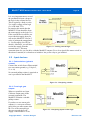
External LED or lamp.............................................................................................33
5.1.2
Relay ......................................................................................................................33
5.1.3
Logic gate (e.g. on VFD invertor) ...........................................................................33
5.2 Input devices ................................................................................................................... 34
5.2.1
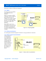
Push switches (galvanic contact).............................................................................34
5.2.2
From logic gate outputs ..........................................................................................34
5.2.3
MPGs .....................................................................................................................35
5.2.4
Rotary potentiometers.............................................................................................35
5.2.5
Rotary switches as potentiometer ............................................................................35
Register Organization.............................................................................................................36
6.1 ROM Register Block....................................................................................................... 37
6.2 Configuration Register Block .......................................................................................... 37
6.2.1
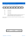
100 - ADDRHI: Modbus Unit ID address high nibble............................................39
6.2.2
101 - CONFIG: Configuration control register........................................................40
6.2.3
102 - COMM0: UART Configuration Control Register.........................................41
6.2.4
103 - FLASH: Flash control register .......................................................................42
6.2.5
104 - PUMP: Pump Control Register ......................................................................44
6.2.6
105 - DEBUG: ModIO™ Debug control register. ...................................................46
6.2.7
106 - CONFIG2: Configuration control register 2 ..................................................47
6.3 RAM Register Block....................................................................................................... 48
6.3.1
1000 - 1039 Liquid Crystal Display Controller registers .........................................49
6.3.1.1
LCD data Registers .........................................................................................49
6.3.1.2
LCD Connector Interface ................................................................................49
6.3.1.3
Register Use Summary....................................................................................50
6.3.2
1040 - DOUT: Discrete Output Register .................................................................51
6.3.2.1
Bit allocation in DOUT ...................................................................................51
6.3.2.2
Discrete Output Safety Charge Pump ..............................................................52
6.3.2.3
Register Use Summary....................................................................................52
6.4 1041 – SSPEED: PWM for DigiSpeed unit ..................................................................... 53
6.4.1
1050 - Encoder1: MPG Encoder read register .........................................................54
6.4.1.1
Overview ........................................................................................................54
6.4.1.2
Register Use Summary....................................................................................54
6.4.2
1151 - DIN: Discrete Input Register........................................................................55
6.4.3
1152 , 1153, 1154 – Analog in Registers.................................................................57
6.4.3.1
Overview ........................................................................................................57
6.4.3.2
Register Use Summary....................................................................................57
6.4.4
1155 – Encoder2: MPG Encoder read register.........................................................58
6.4.4.1
Overview ........................................................................................................58
6.4.4.2
Register Use Summary....................................................................................58
6.4.5
1156 – TickCtr: Timing register..............................................................................59
6.4.6
1157 – Period: Spindle speed measurement register ...............................................59
6.4.7
1158 – Keyboard: Scanned inputs register..............................................................60
Firmware programming..........................................................................................................61
7.1 Preparation...................................................................................................................... 61
7.2 Connecting to the ModIO and erasing flash..................................................................... 62
7.3 Programming .................................................................................................................. 62
Revision data .........................................................................................................................63
Index......................................................................................................................................64
Copyright 2006 ©
Homann Designs
Revision 0.92