1
ModIO™ M100 Modbus Interface Unit - Users Guide
Page 21
communications. If it is in the wrong position then data will not be received from the interface
intended.
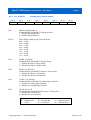
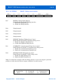
RS-485 Duplex Select (H/F)
Should only be inserted in the exceptional event of using 2-wire (half duplex) operation
RS-485 Receive polarity (JP6)
Normally open – jumper to invert Mark/Space polarity
RS- 485 A load (JP8)
This jumper should be in for the last (only) ModIO™ on the bus. It terminates the line with a 120R
load
RS-485 B Load (JP9)
This jumper should be in for the last (only) ModIO™ on the bus. It terminates the line with a 120R
load
RS-485 TX Polarity (JP10)
Normally open – jumper to invert Mark/Space polarity
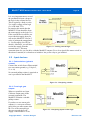
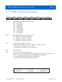
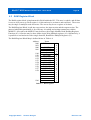
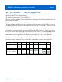
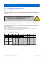
3.10 Discrete Inputs
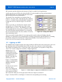
The ModIO™ provides 8 Discrete inputs
(Din0 to DIn7) which feed the DIN
register. Some also are used for the MPGs
and the scanned keyboard logic. These
are accessed via pins on J10.
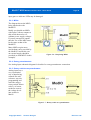
They operate as “Active Low”. That is,
the input device needs to connect the
relevant DIn pin to Ground to represent
the active state.
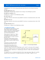
Each input contains a pull-up resistor,
allowing it to be used with switches or
open-collector outputs on MPGs and the
like.
Each input is provided with a LED,
indicating when the input is active.
Figure 3.5 - Discrete Input Schematic
If the input is being connected to a
switching device other than a passive
switch, the voltage from the device should not exceed 5 volts DC or the inputs will be damaged.
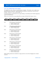
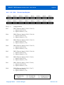
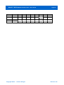
When state of a Discrete input is accessed by the DIN input register, the register contains a bit for
each discrete input. The bit is set “1” when the input is active (i.e. tied to <0.8 volts and LED is
illuminated)
The ModIO™ may be configured to disable the discrete inputs and outputs. That said, it would be
unusual to have a need to do so. To disable the discretes set bit UDIS (CONFIG<2>) to 0.
Copyright 2006 ©
Homann Designs
Revision 0.92