1
ModIO™ M100 Modbus Interface Unit - Users Guide
Page 14
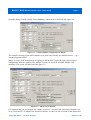
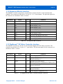
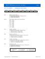
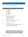
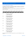
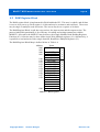
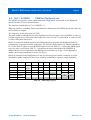
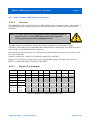
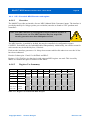
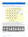
Figure 3.2 – Jumper/Connector Identification
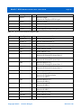
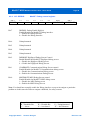
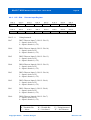
Pin number
Signal
I/O
Comment
1
+5v
-
Power Supply (+5V)
2
Analog 1 Input
I
0-5V Analog Input
3
Analog 2 Input
I
0-5V Analog Input
4
GND
-
Power Supply (GND)
5
Analog 3 Input
I
0-5V Analog Input
6
GND
-
Power Supply (GND)
7
VGnd
-
Connect external VOut supply Ground here
8
+VOut
-
Device supply (VOut) *(It is a power input or output
depending on JP3)
9
DOut0
O
Discrete Output
Shared with Scanned keyboard column select 0
10
DOut1
O
Discrete Output
Shared with Scanned keyboard column select 1
11
DOut2
O
Discrete Output
Shared with Scanned keyboard column select 2
Shared with DigiSpeed Direction
12
DOut3
-
Discrete Output
Shared with Scanned keyboard column select 3
Shared with optional DigiSpeed Enable
13
+VOut
-
Power Supply (VOut)*
Copyright 2006 ©
Homann Designs
Revision 0.92