1
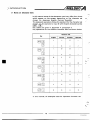
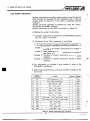
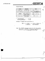
REVISIONS
Print Date
'Manual Number
Jan., 1989
IB (NA) 66189-A
.
K
c
%Themanualnumber
is givenonthebottomleft
Revision
First edition
of the back cover.
INTRODUCTION
n
b
Thank you for choosing the Mitsubishi MELSEC-A Series of General Purpose
Programmable
Controllers.Pleasereadthis manual carefully so that the equipment is used to its optimum.
A copy of this manual should be forwarded to theendUser.
1
,
~
’
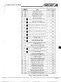
7. COMMUNICATION WITH PROGRAMMABLECONTROLLERCPU
.......................
7-1
.
7-49
IB INAI 6 6 1 8 9 A
.
p___4.-
...
.
8
TROUBLESHwTtNG ...................................................................................
8-1
8-12
8.1
8.2
8.3
9
.
9.1
9.2
APPENDICES ............................................................................................
APP-1
-
APP-12
1. INTRODUCTION
1. INTRODUCTION
..
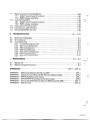
The AD5143 intelligent communication module (referred to
as
"AD51") has two RS232C and two RS-422 interfaces and allows
multitaskprocessingof BASIC programs.
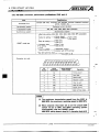
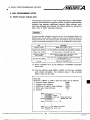
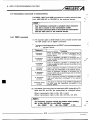
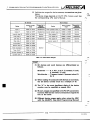
User application programs running in the AD51 allow the following functions:
(1) The A series peripheral devices can be shared.
The AGGPP intelligentgraphicprogrammingpanel
(GPP),
AGHGPLCD
handygraphicprogrammer
(HGP) or AGPHP
plasma handy graphic programmer (PHP) started up by the
SW-AD51P system disk (SW-AD51P) can be used the an I/O
console of the AD51 and allows AD51 programs anddata to be
stored on disk (and ROM (GPP only)). The VT-220 terminal can
also beused as an I/O console.
The above indicated units maybe connectedas shown below:
1
BASIC Program,Data
Connection Example
Input
Storage on disk
GPPlHGPlPHP
GPPlHGPlPHP
______
G PPIH G PIPH P Disallowed
Storageon
ROM
GPP (disallowed
for HGPIPHP)
Disallowed
Generalurpose I10
console
Disallowed
Disallowed
Generalpurpose I/O
console
GPPlHGPlPHP
GPPlHGPlPHP
GPP (disallowed
for HGP/PHP)
Y
General-purpose I/O console
i
.
I.
I
x.
1-1
I6 INAI 66169-A
1. INTRODUCTION
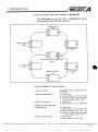
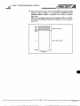
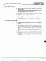
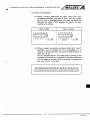
(2) Can be used as a sub-CPU of the PC CPU.
The AD51 reads data (e.g. complicated numerical operation,
function operation) from thePC and calculates and stores it as
required so thatthe PC
CPU
is relievedfrom processing
burden.
1) Storageof setvalue, positioning data,etc.
2) Collection, analysisandcompensationofmeasurement
data
3) Functionoperation of sine, log, squareroot, etc.
4) Logging andstorage ofproduction data
5) Logging andanalysisofinspectiondata
q
1
~
-
n
-
p,
BASIC program
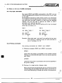
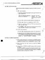
(3) Can beused as a monitoringmodule.
out.
Connected with an I/O console (GPP/HGP/PHP orgeneralpurpose I/O console), personal computerand printer, the AD51
allows the operating status to be monitored and controldata
to be printed
1) Monitor display ......... Indicates the production status, operating conditions, fault definition, etc.
2) Keyboard entry .......... Inputs the production schedule, production quantity, operating procedure
anddata setting.
3) Print out ........... ....... Prints out the production program,
production results, daily report, fault
definition, program data,inspection
results and test results.
4) Clock function
The AD51 includes an on-board, 24hour, real-time clock with leapyear
compensation which allows data to be
transferred by the BASIC program so
that the time-of-the-day data may be
processedeasily.
m
,q'
W'
r
e..........
I/O console
1
RS-232C
AD51
L!*3i
I
1-2
Dl
I
Personal computer
!I L-------RS-232C
~
Printer
n
IB INA) 66189-A
1. INTRODUCTION
(4) Data input from barcode
reader, etc.
The AD51 allows data to be entered from thebar code reader,
magneticcard reader, etc. via RS-232C or RS-422.
The AD51 can be matched with the protocol of theconnected
device for communication by the
BASIC program.
1) Entry of production lot number, product
name, quantity, etc
2) Collectionof measured values, test data.
*
RS-232C. RS-422 device
I
Barcode reader
Magnetic cardreader
Punchcard reader
Mark cardreader
Measuring instrument
(5)Connectionof
AD51 andexternaldevice
The AD51 has one RS-422 and two RS-232C interfaces for 1:1
link with theexternal device, and one RS-422 for 1:N multidrop
link.
The application programs running in the AD51 allows data to
be transferred via the four channels
by the sequence program.
The following examples show 1:1 and 1:N link configurations
of the computer and AD5ls:
RS-232C or RS-422interface
computer
RS-422interface
Max. 32
1-3
IB INA) 6 6 1 8 9 A
1. INTRODUCTION
POINT
I
(I)Inthe
1:l link configuration,RS-422
is usedfor
distances up to 5mmand RS-232C for distances upto
15m.
(2) In the 1 :Nlink configuration, the RS-232C port may be
connected with the host computerbyusingan
RS232C/RS--422converter betweenthe host computer
and AD51.
1-4
IB INN 6 6 1 8 9 A
1. INTRODUCTION
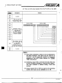
(6) Communication with otherstations in MELSECNET
The AD51 loadedonthe
communication with the
PC CPU in MELSECNET allows
other. stations.
Masterstation
(M)
-
0
0
3
E- 3€
0
E
zu
3
Local station Ztier
3 master station
(LZrn)
Localstation1
Remotestation2
(r2)
(.e 1 )
PC CPUs allowed for communication
(PC used with AD51)
(MELSECNETstationallowedforcommunication)
Station M (master station) ............. (1)Hoststation
(2) All local stations in tier 2 (Ll,
LZm)
(3) Remote 110 station used with special
(R3)
function module in tier 2
Station L (local station) ................. (1) Host station
(2)Masterstationintier2(stationM)
Station Urn (local stationher
3 master station) ..........................
(1) Host station
(2) Masterstation in tier2(station
M)
(3) All local stations in tier 3 ( 2! 1, !2 3)
(4) Remote I/O station used with special
function module in tier 3 (r2)
Station (tier 3 local station) ............ (1) Host station
(2) Master station in tier
3 (LZm)
1. INTRODUCTION
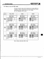
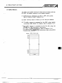
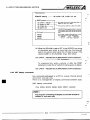
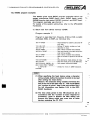
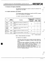
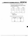
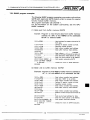
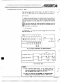
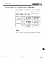
1.1 Notes on Character Sets
In thismanualsomeofthe
charactersused maydifferfromthose
which appear onthe screen, dependingonthe
character set
chosen (i.e. Japanese, English, German, Swedish).
The keyboard operations follow the standard for character
the
set
chosen, so, for example to input @ with English characters press
?
-
,n!,
"
"-1
m,
I
\
.
Key codes are given in Appendix 4, paragraph 3.
Key operations for the different character sets are shown below.
T
Character
English
German
Set
Swedish
\
Japanese
I
I
Ll
IO
\
§
f
#
#
#
$
$
0
$
In this manual, all examples use the Japanese character set.
1-6
IB INAI 66189A
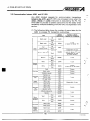
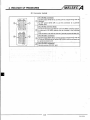
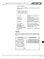
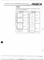
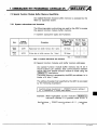
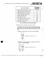
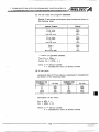
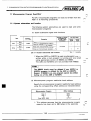
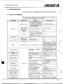
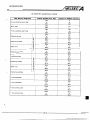
2.3 Peripheral Equipment
-
The following table lists the peripheral equipment suitable for
use
with the AD51
Intelligent
:ommunication module
EP-ROM
Battery
TY P
Remarks
AD5143
Main unit
RAM support battery supplied
8KROM
16Kbvtes. for channels 1 and 2
1GKROM
32Kbytes, for,channels 1 and 2
241( bytesavailable to AD51
Fordetails,refer to Section 3.4.2
For CRAM supportandreal
AGBAT
time clock
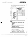
3 Consists of the following models:
I
I
Intelligent GPP
I
Type
AGGPP
Rmarks
Programming unitwith CRT.
Equippedwith ROM writer, FDD,andprinterinterfacefunctions.
ISW[:I-GPPAEE/EGI disk systemseries
AGGPPE-SET
I
I
AC30R4
I
I
Kseriessystemdisk
SW[:]-GPPKEVEG
SW[:I-GPPU
A
I
Userdisk(3.5inch,
formatted)
Cableconnection
for AD51
ofand
AGHGP,
ACPU,
AJ71C24-S3
Note: -EE;
Englishversion,
I
EG; Germanyversion
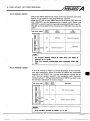
3 Consists of the following:
4..
r
....
1
Handygraphic
programmer
AGHGPE-SET
I
1
TYP
AGHGP
Remarks
Programming unitwith LCD.
Equipped with FDD and printer interface
functions.
S@:I-HGPA€EIEG
Aseriessystemdisk
SWI-HGPKEEEG
Kseriessystemdisk
SW[:I-GPPU
AC30R4
I
inch, (3.5 disk User
formatted)
Cable forconnectionofAD51andAGHGP,ACPU,AJ71C24S3
Note: -EE;
Englishversion,
EG; Germanyversion
~~
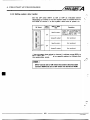
System software package for the AGGPP or AGHGP
(back-up copy provided)
Systemdisk
Userdisk
SWO-GPPU
Compositevideocable
AClOMD
Userdisk(already
formatted) for storingprograms.
Optionalcable for GPP external monitor lm(3.28ft) length
General-purpose
110 console
VT-220
Display control codesequivalent to VT-220.
Printer
KGPRE
K7PRE
For program hard copy and data print out
KD51PR
For printing data
RS-422cable
AC300R4
CablebetweenAD51
and AGGPP
3m(9.84ft)length
RS-232C cable
AC30R2
ConnectioncablebetweenAD51
and printer and for VT-220.
3m(9.84ft)length
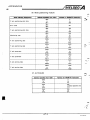
Table 2.1 SystemEquipment List (Continue)
I
I
2. SYSTEM CONFIGURATION
Ink ribbon
Printer paper
KIPR-R
Ink ribbonfor KGPRE
K7PR-R
Ink ribbon forK7PRE
KD51PR-R
Ink ribbon forKD51PR
KGPR-Y
Printer paper for KGPR
KD51PR-Y
Printer paperfor KD51PR
.*-
L,
~
Interface connector
232-CON
Connectorfor
RS-422 and RS232C interfaces
Table 2.l System Equipment List
C
..
, ..
I
4. PRE-START UP PROCEDURES
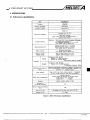
3. SPECIFICATIONS
3.1 PerformanceSpecifications
kern
Processor
HD641W.
Programlanguage
GPC-BASIC
Number of tasks
Maximum 8
~~
Taskstart conditions
Internalmemory
~
-~
Power on
Interrupt from PCCPU
Real time interrupt
to 9.99 seconds in
units
of
second.
0.01
[ Set in the range0.01
1
Two 16KROMs loaded
*Fordetails,refer to Section 3.4.
General-purpose 110
General-purpose input : 13 points
General-purpose output: 10 points
*Fordetails,refer to Section 3.6.
Buffer memory
3K words (6Kbytes)
*Fordetails,refer
to Section 3.7.
Memory protect
addressrange
4FOO to 4FFF (systemdataarea)
8000 to DFFF (channel1 to 4)
RS-422
Interfaces
RS-232C
Conforms to EIA.RS-422.
Channel1: D shell connector.
Channel2:Terminalblock
Transmissiondistance:
5500n
Conforms to EIA.RS-232C.
Channel 3, 4: D shell connector.
Transmissiondistance:
d15n
4rithmetic and logic unit
MU)
Performs high-speed processing of BASICs intrinsic func
ex
tions (trigonometric,inversetrigonometic,logarithm,
ponential, 6,
absolutevalue).
Clock element
Year, month,
day,
hour,
minute,
second
Readwrite
24 hour mode, automaticleapyearcompensation
'ower failure compensation
Internal memory,
lithium battery for back-up of real time clock
Totalback-up time: 130days
years
: 5
Battery life
Console
AGGPP,AGHGP,A6PHPVT-220
Number of
48
rternalcurrentconsumptior
(5V)
1.3A
I/O points occupied
Size mm (inch)
Weightkg
1.1(2.42)
(Ib)
Tabk 3.1 AD51 Performance Specifications
3-1
IB INAJ 6 6 1 8 9 A
4. PRE-START UP PROCEDURES
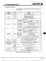
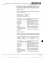
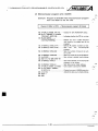
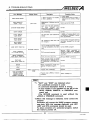
3.2InstructionSet
TheAD51 is programmedin GPC-BASIC.
In addition to the BASIC commands a series of subroutines are
available which can be called from the BASIC program.
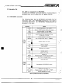
3.2.1 GPC-BASIC commands
The followingtableliststhe
GPC-BASIC commands. For full
information refer to the "GPC-BASIC Handbooks". The graphics
commands described in the "GPC-BASIC" Handbooksare not
available on the AD51.
Command
I
Function
AUTOAutomaticgeneration
I
BYE
Returns to BASIC program address
data
screen.
COMPILE
I
DELETE
Compilesmultitaskexecutable
program
Deletes program from specified line number
number
to specified
line
Correctsstatement in oneline
EXECUTE
Run
Key
:ornmand
I
of program after
"RUN"
"COMPILE"
or
Displays program on screen
i
I
1
I
LLIST
NEW
RENUM
Executes
C
I
Resumes program run after BREAK
CONT
1
of line number
I
1
A
RUN
-
1
I
Prints out program
Erases program
I
Renumbers line numbers
I
program
Displays I/O console
Deletes line
BREAK
Resumes
I
I
program run after
stop
and
"CONT"
Callsmachinelanguage
program
Clears CRT screen
Program
:ommand
Closes specified RS-232URS-422 channel.
CLOSE
I
FOR...NEXT
I
Moves
GOT0
of
Declares
end
program run
Repeats program run from "FOR" to "NEXT"
to
number
specified
line
Table 3.2 BASIC Command List (Continue)
3-2
I
I
I
n
b
n,
I
IB INAl 66189-A
4. PRE-START UP PROCEDURES
Is equalto
Is notequalto
<
>
<=
>==
Darison
operator
Is less than
than
Is greater
than greater Is not
Is not less than
#
Neaation (NOT)
8
Logicalproduct (AND)
I
Y
Logicalsum
(OR)
Exclusivelogicalsum
(EXOR)
Table 3.2 BASIC Command List
Where
commands
have
several
options
(indicates
shaded (
) maybe usedon the AD51.
I
as
etc.)
only
those
4. PRE-START UP PROCEDURES
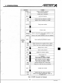
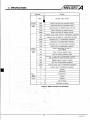
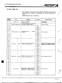
3.2.2 System subroutines
System subroutines are machine code programs used for special
AD51 functions (for example PC CPU transactions etc.). They are
already written in channel 0 of the AD51 at specified address
locations.
System subroutineoperation is initiatedbyusingthe
"CALL"
command in the BASIC program.
Systemsubroutines on the AD51are shown in Table 3.3.
m
-
,n
8
,
L'
[Initializingthesystemsubroutine]
1) The system subroutine is called from the GPC-BASIC program
usingthe"CALL"command.
2) The format of the
I
CALL statement is as follows.
r
1
A=CALL (variable1,variable 2, [variable 3, variable 41)
-
Variable 1:Always 0. All systemsubroutines are located in
channel 0.
Variable 2: Head address of system subroutine in channel 0
(see table 3.3)
Variable 3: Variable for system subroutinestoredin(D)(E)
registers.
Variable 4: Variable for systemsubroutinestored
in(B)(C)
registers.
3) For informationonvariable
GPC-BASIC Handbooks.
3 andvariable
i
n
. ...
4, refer tothe
4) Before executing the CALL command, transfer variables to the
work area.
Function
Y
1
I
I
SA1
I
BIN
~
ASCIISAN
3
BIN SNA
4
5 ASCIISAF
6 Real
-
ASCII (hexadecimal)
SFA
-
-
0
SFIXD
32-bit
2
SDB4
I4
SDB6
1
o
0
I
I
I
8060~
8063~
ASCII (decimal)
0
8075~
-
0
8066~
0
8069~
-
real number
ASCII
real number
integer
-
I
I
0
0
I
I
806C~
806F~
I
I
0
~ODEH
32-bit
integer
0
80E1~
0
8042~
BIN
0
8045~
-. 6-digit BCD
0
8048~
0
8048~
-
number
-
4-digit BCD
6-digit BCD
-
BIN
r
I
point number
4-digit BCD
BINSBD6 I3
I
I
I
Address
8072~
-. 32-bit
floating
floating
point
1 BIN SBD4
I
BIN
I
0
number
32-bit
integer
Channel
BIN
(decimal)
Integer
SFLTD
-
ASCII (hexadecimal)
Real number
9
I
m
-.
-,
,
Table 3.3 System Subroutine List (Continue)
Y
36
IB (NAI 6618SA
4. PRE-START UP PROCEDURES
1
Function
Channel
I
Address
BIN addition (24 bits)
~~
~
~~
~
subtraction
BIN
SBS 16
BIN
SBM
17
1181
SBW
bits)
I
bits)(24
multiplication
(24
BIN division (24 bits)
Write to clock element
(year,month,day,
hour, minute, second)
I
0
8051H
0
80%
0
I
803C11
Read from clock element
(year, month, day, hour,minute,second)
SCB
805711
803F~
0
8078~
CPU run/stop check
0
8030~
SKR23
Remote run of programmable controller CPU
0
8033~
SKP
24
Remote
ofstop
0
8036~
SRB
25
Receives specified byte length of
specifiedchannel
SPC21
Discrimination of programmable controller CPU
SKC22
SWB
Programmable
controller
26
SRC
J28j
SRF
1
1
programmable controller CPU
datasent to
Sends specified byte length
of data from specified channel
Reads the number of bytesofdatareceived
byspecifiedchannel
Reads the number of vacantbytes
in receivebuffer of specifiedchannel
8009~
0
I
1
0
0
I
1
1
SR2
I3l
SAE
1321
SEA
(331
STC
1 4
SRP
I
I
I
I
35
SADR
SADW
1381
(391
No codeconversion of sendreceive data
ofspecifiedchannel
Reads the number of remaining bytes
in sendbuffer of specifiedchannel
Reads status of specified
channel
I
1
1
1
Readsdata from buffer memory
SW2 36
1371
Converts all sendheceivedata
specified
of channel
to EBCDIC code
SADT
I
I
I
Writesdata to buffermemory
Readsdata from data memory
of programmable controller CPU
Writesdata to datamemory
of programmable controller CPU
Randomly
writes
data
to data memory
of programmable controller CPU
Entersdata randomly read from data memory
800F11
801211
801 5~
byXon/Xoffcodes
by DR terminal
800C11
1
I
I
Table 3.3 SystemSubroutine List (Continue)
0
0
0
0
1
I
I
I
801811
801En
802111
8016~
802711
0
8000~
0
8003~
0
0
0
I
1
I
807E11
8081~
80%
4. PRE-START UP PROCEDURES
N
(41
Subroutine
S-m
SADMl
I
I
I
I
SAAR
42
1 4
SAAW
44
SAPR
45
SAPW
1461
SAPS
48
SIR
49
sc2
1501'l SAER
I
Readssequence program
sequence
Writes
I
program
0
80934
Analysis
of
request
programmable
controller CPU parameters
~ _ _
~ _ _
~~
Sets S R ~ S Wretry
~ time
I Reads datafromextension
tile registers
of
PC CPU
Defines PC
CPU
extension file registers
to be monitored
Monitors PC 'W extension file registers
data
specified In monitorentry
55 *2 SAMR
Reads microcomputer program from PCCPU
56 ' ~ S A M W
Writes microcomputer program to PC CPU
SACW
59
SATR
1
Reads comments from
CPUPC
I
0
Readsdata from special function module
buffer memory
0
0
I
-I
I
0
I
I
1
Writescomments to PCCPU
Writesdata to special function module
buffer memory
a
O
0
52 '1 SAET
58
I
I
Interruption to &egrammable controller CPU
Randomly writes data to extension file registers
of PCCPU
SACR
WDH
Writes programmable controller CPU parameters
Writesdata to elrtension file registersof PC CPU
1571
I
809011
Reads error code
I
0
808Au
0
51 'l SAEW
1531' SAEM0
I
0
CPU parameters
Reads programmablecontroller
1
-
Randomly
reads
data
from data memory
of programmable
controller CPU
.
-
I
I
1471
SIT
Function
1
O
O
0
0
0
802A~
I
I
8024~
800611
I
~ B D H
8 x 0 ~
I
I
1
8x311
8ocCH
800211
80D511
0
80Dh
1
I
I
I
I
~ODBH
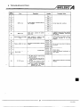
Table 3.3 SystemSubroutine List
Wheresystemsubroutineshaveseveraloptions(indicated
maybeused
on the AD51.
shaded (
Systemsubroutinesindicated
books.
as
arecoveredinthe
as
f
\
~ C F H
0
0
I
W
onlythose
GPC-BASIC Hand-
System subroutines marked *1 may only have access to the
A3ECPU, ABCPU,
A3NCPUand A3HCPU.
System subroutines marked *2 may only haveaccess to the AlECPU, AlCPU,
A1 NCPU, NECPU, A2CPU, A2NCPU. ABECPU, ABCPU, A3NCPU and A3HCPU.
U-v
IB (NA) 66189A
4. PRE-START UP PROCEDURES
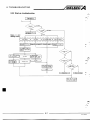
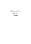
3.3 SoftwareConfiguration
The followingshows
a blockdiagram
configuration indicating how the various
of the AD51 software
areas interact.
Multitask executed
I
L-----,
os
Storage of user program
anddata onto disk.
Storage of user program
and data onto ROM.
User program
Operation is enabled only in offline
mode (when multitask or BASIC
program -is not being executed).
Fig. 3.1 SoftwareConfiguration
(1) As shown in Fig. 3.1, a maximum of 8 user programs may be
processed in parallelunder
thecontrol
of the real time
monitor.
(2) "Power on", "interrupt from ACPU", and "real time interrupt"
are available as starting conditions for the user program.
(3) Each task can only be written in BASIC.
-.
3-9
IB INAI 661ESA
A
4. PRE-START UP PROCEDURES
3.4 Memory
. ,
. .
fl
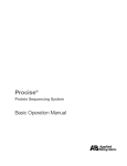
3.4.1 Memory configuration
The AD51 is a 2-80based system. Toexpand the memory size
from 64K bytes the second 32K bytes are duplicated in additional
channels as shown in Fig. 3.2 below.
POINT
OOOOH
I
~FFFH
os
RAMuserworkarea.
I
On board
RAM or ROM
On board
RAM or ROM
I
Memory channel
OS
0
F
RAM or ROM
On board
RAM or ROM
Flfl
inputs
*2: Channels 3 and 4 become available
When ROM is loaded
On board
On board
M M or ROM
1
outputs
8oooH to ~ ~ F (2K
F Hbytes)
FFFFH
kw
Bytes with the following head addresses in the
User Work area are used for direct accessing of
the Goner8l-Purpow 110 aSsQned to tha AD51
using the PEEK and POKE eommands (see Section 7.1.1):
Common
area
32K bytes
Channel
area
32K bytes
f4..
On board
On board
On board
1
2
RAM
RAM
3
4
User memory area (Max. 112K bytes)
0
to
BFFH
U
*3: Buffer memory
(16 bit)
Fig. 3.2 Memory Map
POINT
I
*(1) The RAM user work area, (addresses 6000n t o 67FFn)
is in the common area and can be accessed by the
user programs in any of channels 1 t o 4.
*(2) The memory area may be expanded by adding ROM
t o channels 1 and/or 2.
*(3) Thebuffer
address rangeis OOOn t o BFFn which
represents 3K words (6K bytes) of buffer memory.
Each buffer memory address represents 1 word. (i.e.
16 bits)
P
3-10
IB lNA1 66189A
4. PRE-START UP PROCEDURES
POINT
I
.
'
I
(1) The installation of a ROM shifts the corresponding
RAM address range t o a different channel. (e.g.
Installing 8K of ROM at channel 1 addresses 8 0 O O n t o
BFFFMmoves the RAM area t o channel 3 addresses
8 0 0 0 n t o BFFFn.
(2) Two shorting pinsare used t o SQoPify RAM or ROM i n
channels 1 and 2. The RAM area is moved as follows
dependimg OR the pin se#ing in each channel.
RAM position
ROM position
W
R
O
M
WithoUtaoM
RAM and ROM 8man
COrrvGt
coincide.
correct
Th.FaMH.rch#gsr
channels as though
ROM was t l l i t a h d .
(3) Only 24K bytes are valid (addresses 8oooa t o DFFFn)
when feKROM is used.
The-% bytes from E W to FFFFnare used in the RAM
area andtheprogram
in this ROM address range
cannot be executed.
(4) FOFRAM area memory protect, refer t o Section 4.3.1.
/MELSEC
a SPeClflCAnONS
4. PRE-START UP PROCEDURES
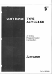
3.4.3 Storing system data on ROM
,,-.
Systemdata
(e.g. multitask set data)requiredforprogram
execution of eachtask may be stored to ROM.
The system data located in the common area is stored to the first
256-byte area of the ROM installedonchannel 1.
Common
area
\
Channel 0
8000~
Channel 1
8 0 0 0 ~ t o80FFn
(Systemdata)
ROM area
to
FFFFH
FFFFH
RAM area
(1)Afterthe systemdataisstored
on ROM, addresses 81OOH to
FFFFH are used as a user memory area and 8O0OH to 80FFH
cannot be used as a user area (program area, work area).
(2) After the systemdata is stored on ROM, the RAM area of
channel 4 can be used
as a program area but that ofchannel 3
may only be used as a work area.
(3) With the system
data transfer switchON, multitask is executed
after the system data is transferred from 8O0OHto 80FFH of
channel 1to thesystem dataarea (~FOOH
to 4FFFH)at power on.
3-13
IB (NAJ 6 6 1 W
4. PRE-START UP PROCEDURES
3.5 InterfaceSpecifications
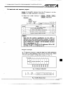
3.5.1 RS-422 connector specifications (CH1)
kern
ConnectedUnit
_
_
_
_
_
~
~
~
~
~
~
~~
_ _ _Specifications
.
AGGPP, printer with
~
~~
~
RS-422, personalcomputer,
Transmissionsystem
Conforms to EIA. RS-422.
Synchronous system
Asynchronous system
Baudratesetting
USART mode setting
(300,600, 1200,2400, 4800, 9600 BPS selectable)
Parityabsent
-EParity
Parity bit setting
<Stop
topbitsetting
etc.
present
Stop bit
bit
1
G
d
parity
d parity
Character data
bit setting
Data' 7 bits
-Data 8 bits
-&
Communication
control setting
XON/XOFF control
ontrol with DTR terminal
Connector pin outs.
20
30
40
50
'O
loo
'lo
lZc
13 0
0 1 4
0 15
0 16
0 17
0 18
h
0 19
0 2 0
0 21
0 2 2
0 23
0 24
0 25
*Connect pin 21 to thesignal ground of theexternalequipment.
(1) The maximum transmissionspeed from the AD51is
9600 BPS, the maximum receiving speed is 4800 BPS.
(2) When channel 1 has been set as an I10 console (DIP
switch 16set to ON), the AD51 operating system
automatically sets the USART mode:
4800 BPS,even parity,stop bit 1, character data 8
n
-*
4. PRE-START UP PROCEDURES
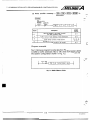
3.5.2 RS-422 terminal blockspecifications (CH2)
Specifications
Item
AD51, personalcomputeretc.
Connected Unit
Transmissionsvstem
Conforms to EIA. RS-422.
Synchronous system
Asvnchronous svstem
r B a u d ratesetting (300, 600, 1200,2400,
USART mode setting
i
t
Parity bit setting
Parity
absent
-IParity
present
<Stop
Stop bit setting
k h a r a c t e r data
Data
setting
bit
Stopbit 1
bit
4800, 9600 BPS selectable)
veri
S
d
parity
d parity
__c Data 78 bits
bits
Terminalblockpinouts.
Terminal
Block
SDA
I
Diagram
Number
I
I
Signal
Didon
Remarks
I
Send data
(SDB)
I
FG
1
Signal
ground
(SG)
Frame
ground
The maximum transmission baud rate from the AD51 is
9600 BPS. The maximum receiving baud rate is 4800 BPS.
4. PRE-START UP PROCEDURES
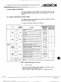
(CHa and 4)
3.5.3 RS-232C connectorperformancespecifiostions
Specifications
Item
ConnectedUnit
Console(CH3
only), computerwith RS-232C interface,personalcomputer,
printer,modem, etc.
Transmissionsystem
Conforms to EIA. RS-232C.
Transmissionspeed
300, 600, 1200, 2400, 4800,9600 selectable
Synchronous system
Asynchronous system
F B a u d ratesetting (300, 600, 1200,2400,
USART mode setting
t
Stop bit
bit
Stop bit setting-&op
Character data
setting
bit
L
4800, 9600 BPS selectable)
1
Data 7 bits
-+
8 bits I
Data
Communication
control
setting
ontrol
with
XON/XOFF control
__cc
*Set CH3 with the front
DTR terminal
DIP switches (SWl to 8).
Connectorpinouts.
SignalDirection
Signal
Insideoutside
Abbreviation Number
Pin
I
POINT
Description
1
FG
2
SD
+
Senddata
3
RD
c
Receivedata
4
RTS
+
Reauest to send
5
CTS
c
Clear to send
6
DSR
t
Dataset ready
7
SG
20
I
DTR
Frame ground
I
-
Signal ground
1 Data terminal
ready
I
(1) The maximum transmission speed from the AD51 is
9600 BPS, the maximum receiving speed is4800 BPS.
(2) When channel 3 has been set as an I10 console (DIP
switch 16 set to OFF), the AD51 operating system
automatically sets the USART mode:
4800 BPS, parity absent, stopbit 1, character data bit8
I
4. PRE-START UP PROCEDURES
3.6 I/O Interface with Programmable Controller CPU
The digital I/O bus may be used for communication between the
PC CPU and the AD51. The following table indicates the function of
each signal. The drive number will vary depending on the AD51
slot location; in the table the
AD51 is assumed to be in slots 0 and
1 of themain base unit.
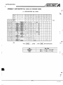
(1) There are 48 input signals to thePC CPU (X00 to X2F) from the
AD51.
x 10
Address 6940~
x 11
87 B6 85 841B31821811BO
L L L L J
x 12
Address 6 9 2 0 ~
87 B6 85 B4 83 82 B1 BO
L
L
L
X13
X1 4
Switched
onloif
by
the BASIC program
X15
contacts
the
and
X16
L
usedinthe
sequence
X17program.
(Known as Generalpurpose
inputs)
X18
I
x19
I
-
indicate
X1
D AD51
an
X1 E
CPU fautt
Unused
X1 F
I
Switched on to
I
3-17
IB INAI 661ES-A
4. PRE-START UP PROCEDURES
(2) There are 48 output signals from the
output
PC CPU to the AD51.
I
Address
Description
Number
YO0
to Unused
YOF
Y10Maybeused
by
to the
PC CPU as extra
Y1F
internalrelays(MI.
Y20
87 B6
Y21
Y22
y23
y24
y25
Address 6800~
Address 6820~
85 84 83 B2 B1 BO
A
L
Switched odoff in
the sequence program
andread by
the BASIC program
(known as Generalpurpose outputs)
1
Y22
Y23
Y26
Y24
I
Y 27
8
Y28
L
Y27
This output may be
Y29
/El
Y25
Y26
L
Y28
used to start one task
in the AD51
designated as an
interruptprogramby
its task start condition.
Unused
POINT
I
(1) Input X1D is switched on when an error is detected by
the AD51 hardware. This signal may be used
as an
interlock in the PC sequence program t o control PC
accessing of the AD51 buffer memory (i.e.
instructions).
(-I
(2) Switching output Y29 on will start the task whichhas
its start condition specified
as 'interrupt from ACPU".
The startconditionisdefinedduring
"mutti task
setting".
(3) Output signals Y2A t o Y2F are used by the operating
system and must not be switched on or off.
3-18
IB (NAI €6189-A
4. PRE-START UP PROCEDURES
3.7 Buffer Memory
The AD51 uses a buffer memory fordata communication with the
PCCPU. (The buffer memory is not battery
backed.)
(1) Buffer memory addresses are OOOH to BFFH (3K words).
See the memory map in
Section 3.4.
(2) Buffer memory data is made upof
16 bits peraddress.
(3) The buffer memory is accessed by the AD51 using system
subroutines (SR2, SW2). For details, refer to Section 7.2.1.
(4) Thebuffermemoryis
accessed bythe PC CPU usingthe
and
application
instructions.
For readand write procedures, refer to Section 7.2.2.
For details of the
instructions, refer to theACPU
ProgrammingManual.
1-1
v)i%-]
3-19
IB lNA1 ffi18SA
4. PRE-START UP PROCEDURES
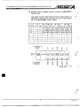
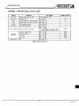
3.8 Communication between AD51 and PC CPU
Any AD5,l initiated requests forcommunication
transactions
time taken to process a system subroutine and the delay times
caused by multiple accessing of the PCCPU are explained in this
section.
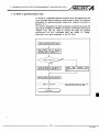
(1) The following table shows the number of scans taken by the
AD51 t o process PC transactionsubroutines.
Batchread
Batch write
*li
Bit
I
SADR
Word
SADW
Bit
(random write)
Device
memory
arameter
I
Bit
I
Bit
Word
Read
Main
I
1
Sub
Read
Batch write
1 scan for device "R" only
(Independent of scan
for otherdevices.)
SADMl
1 scan
1 scan
'
I
I
2 scans
(1 scan for T/Cset value)
sAAw
SAPR
SAPW
I
I
Analysisrequest
arameter
(PC)
Buffer
memory
Remote run
SKR
Remotestop
SKP
PC type mode
I
I
I
Batch write
I
I
read
Batch
Batch write
ixtension
file
register
Microomputer
Irogram
:omment
Special
module
buffer
nemory
. .
1
SAER
SAET
SAEMO
E
Write
Independent of scan
I
I
SAE W
Monitor
Main
Sub
l
SAPS
1 scan
SR2
sw2
Random write
Read
2 scans
SPC
Monitor data entry
'
2 scans
2 scans
readBatch
C
(2 scans 1
forscandevice'R")
SADMO
Sub
Write
Number of Scans
ReauiredforProcessinn
Independent of scan
Word
Monitor
ktquence
program
I
SADT
Word
Monitor data entl
SAAR
System
Subroutine
SAEMl
SAMR
SAMW
Batchread
2 scans
I
1 scan
1 scan
2 scans
2 scans
Batchread
Batch write
3-20
SAW
1 scan
IB INAI 66189-A
4. PRE-START UP PROCEDURES
1
POINT
I
System subroutines SRZ and SW2 (buffer memory read,
write) allow m u . 3K words (6K bytes) to be transferred
between the PC CPU and AD51 at one time independently
of the [END!,
or
instruction execution in the
sequence program.
1
m\ W
I
1
(2) Requests for communication transactions with the PC CPU may
also come from other sources, these are listed below and are
processed in the same way as AD51 transaction requests. Only
one transaction may be processed per PCCPU scan so that a
delay of 1 to 5 scans is possible before the AD51 transaction is
processed if severalof these requests overlap. The following list
gives the transaction requests inpriorin/ order.
1. Programmablecontroller CPU OS program
2. Peripheral equipment (e.g.A6GPP)
3. Optical or coaxial data linkunitincorporated
in CPU
module
4. Optical or coaxial data link module in 3 hierarchy system
AJ71 P22JR22
5. Processing request from AJ71C24-S3 or second AD51
Hence, if continuous processing requests are received from
the A6GPP and AJ71C2443,communicationbetweenthe
AD51 and PCCPU is only madeonceeverythree
scans.
(3) When a system subroutine is called which
accesses the PC
CPU there is a delay while the PC CPU prepares the appropriate data. During this delay time, the AD51 switches tasks to
optimize scan time. In the example shown below, threetasks
are executing subroutine which access the PC CPU. Task one
provides the first processing request to the PC CPU which
prepares the requested data. Duringthis delay the AD51
switches to task 2 which isunable to pass its processing
request to the PC which is still dealingwith the one from task
1. The AD51 therefore switches to task 3 for which the same
situation exists. Onlyafter task 1s requesthasbeen
fully
processed can task 2s request be dealt with. Similarly task 3
must wait untiltask 2 been processed. For details of othertask
switching, refer to the GPC-BASIC Handbook.
END
END
END
PC CPU
END
END
AUXSS completed
Task 3
I
I
16 lines
16 lines
16 lines
16 lines
completed
ndmiu
Unabla to Qiva processing
r q u a l m d wait,
16 l i n n mmphted
3-21
I6 INN 6 6 1 6 9 4
--
4. PRE-START UP PROCEDURES
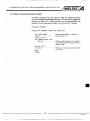
3.8.1 Transmission time in MELSECNET
Transmissiontime (TI) is calculated as follows if data transmission
is madeto thespecified PC CPU which is not used with the
AD51 in
MELSECNET.
Master station
-
localstation
,n,
b
F]
+
Transmissiontime (TI) = ((periodequivalentto
instruction processing time) (1 scan time of station used
with AD51)) X &
Masterstation
-
remotestation
+
Transmissiontime (TI) = ((periodequivalentto
instruction processing time) (1 scan time of MELSECNET
masterstation)) X &
Read "2" marked
as "3" whencommunication is
made to the corresponding station for the first time after
power on or CPU reset.
Read "2" as "1 " from the second communication on when
the number of stations communicating
is 64 or less.
-
Factorof
C
transmission time (TI) delay
Transmission time obtained from
anyof the aboveexpressionsshould be doubledifthecommand
executed
requires two scans for transmission (e.g.device " R " write).
Transmission time shouldbe multiplied by the (number
of
stations monitored
1) the
if other
link
stations
are
monitored by the A6GPP.
*For moreinformationon
data link, see the DataLink
System User's Manual.
r )
9.-
Example:Readinglocalstation
device memorywiththe
AD51
loaded on the MELSECNET masterstation
(Conditions: L < LS < M, M = 80ms, a 1 = 10ms)
+
a 1X 4
Transmission time (TI) = ( M X 4
= (80 X 4
10 X 4 i- 80) X 2 = 880
+
whereM
= MELSECNET masterstation
+ M) X 2
scan time
a 1 = MELSECNET master station link refresh
time
LS = link scan time
L = MELSECNET localstation
POINT
scan time
I
On some conditions, a considerable delay
will occur for
data transmission to the PC CPU which is not used with
the AD51 in MELSECNET.
Transmission time can be reduced by performing communication only between the AD51 and the PC CPUs used
with the AD51 (PC No. FF.) and using MELSECNET data
link (6, W) for communication.with the other PCCPUs.
3-22
IB INAI 66189-A
r
-
/MELSEC
4.
UP PROCEDURES
8. PRE-START
SPECIRCATIONS
3.9 AD51 Communication
Data communication between theAD51 and external devices(e.$
computer, I/O console, printer) is madeusing
RS-232C and
RS-422.
Data communication is made via the transmission and receive
OS of the AD51. The
bufferswhicharecontrolledbythe
transmission and receive buffers are controlled individually for
channels 1 to 4.
Externaldevice
AD51
Transmission
buffer
User program
h
0
Transmission
(such as
computer,
110 console,
printer)
(BASIC program)
0
Receive
~
Fig. 3.3 AD51 Communication
(1) When the transmission command (PRINT,LPRINT, SWB) is
executed inthe user program,transmissiondataisstored
to
thetransmissionbuffer.
If theempty area of transmissionbufferis
less thanthe
transmission data length, the transmission command execution is stoppedafter as much data is storedto the transmission
buffer.
The remaining transmission data is stored when
an empty
area is made in the transmission buffer by data transmission
to the external device.
Transmission
buffer
Transmission
buffer
Transmission
data
~~
...
..
As transmission data cannot
be stored to the transmission
buffer,
transmission
commandexecutionisstopped.
1
I
3-23
IB (NAI 6618SA
U
4. PRE-START UP PROCEDURES
(2) Data is transmittedinthe
same order as stored 30 the
transmission buffer when the external device is enabled
to
receivedata
by communicationcontrol
(DTR controlor
XonlXoff control).
(3) Data received from the external device is stored to the buffer
memory.
Whentheempty
area of the receivebufferis
reduced,
communication control alerts the external device to receive
disable.
(4) Execution of the receive command (INPUT, INKEY, SRB) in the
user program transfers data from the receive buffer touser
the
work area.
teceive buffer
buffer
Receive
-
n
-
/MELSEC
smwmnQus
4.
3. PRE-START UP PROCEDURES
3.10CommunicationControl
The AD51 has two types of communication control, DTR control
andXon/Xoffcontrol.Communicationcontroldefaultsto
DTR
control.
Either control may be selected by executing the corresponding
system subroutine as follows:
DTR control ...........*Execute SHD.
Xon/Xoff control-.....Execute SHX.
a
Channel 2 (RS-422 terminal block) is not allowed for communication control change.
(1) AD51 transmission
The AD51 sends data after confirming that the externaldevice
isready to receive.
The external device used must
be capable of alertingthe AD51
to receive disable when there is an empty area of 5 or more
bytes in the receivebuffer.
(2) AD51 receive
TheAD51 receivebufferhas
511 bytes.
The AD51 notifies the externaldevice of receive disablewhen
the empty area of the receivebufferis 7 bytes or less.
The AD51 alerts the external device to receive enable when the
empty area of the receivebufferis 32 bytes or more.
External Device Receive Control
AD51 Remive Conttol
(Receive disable)
(Receive enable)
AD51 receive buffer
AD51 receive buffer
External device
receive buffer
bytes
3
7 bytes
orless
I
POINT
,
I..
3
Alerts the AD51 to receive disable when there is a 5 or more
byte empty area.
1
The external device connected to the AD51 must have a
receivebufferand
be capable of alerting the AD51 to
receive disable when there is 5 bytes or more left as an
empty area.
Any external device that performs communication handshake in units of 1 byte cannot be connected to theAD51.
3-25
I6 INAJ €61&2-A
4. PRE-START UP PROCEDURES
3.10.1 DTR control
,-
Performscommunicationcontrolusingthe
signal.
notice
ready
terminal
and
signal
datadeviceready
-
,-!
RS-422 : RSNRSBand CSNCSB
RS-232C:
DSR and DTR
(a) The data device ready signalis switched onto send data from
the transmission buffer to the external
device.
The datadevicereadysignal
is switchedofftostopthe
transmission.
(b) The terminal readynoticesignal is switched off when the
empty area of the receive buffer has become 7 bytes or less.
The terminal readynoticesignal
is switchedonwhenthe
receive bufferempty area increases to 32 bytes ormore after
the receive command (INPUT,INKEY, SRB) is executed in the
user program.
F
i.
3.10.2Xon/Xoffcontrol
Performs communication control using the Xon
Xoff code (13H).
device.
external
code (1114 and
(a)TransmissionisstoppedwhentheXoffcodeisreceived
during transmission of data from the transmission buffer
to
the
TransmissionisresumedwhentheXoncodeis
received.
-
A
r7 5'
(b) When the receive buffer empty area is reduced to 7 bytes or
less, the AD51 sends the Xoff codeto alert the externaldevice
to receive disable.
The AD51 sends the Xon code to notify the external device of
receive enable when the empty area increases t o 32 bytes or
more after the receive command (INPUT,INKEY,SRB)
is
executed in the user program.
3-26
IB INAI 6 6 1 8 9 A
,r
-
/M.ELSEC
4. PRE-START UP PROCEDURES
4. PRE-START UP PROCEDURES
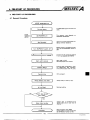
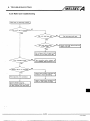
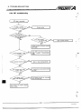
4.1 GeneralProcedure
I
AD51E systemstart-up
t
I
I
Connectbattery
AD51E
hardware
setting
SetRAM/ROMpin
Set DIP switch
1
I
I
I
I
The memory map depends on
RAMlROMassignment.
Select 110 console channel andmultidrop terminal resistance.
Before writing or correcting a program, set the M-PROTECT switch to
OFF.
Turn M-PROTECT switch off
[connect VO console to AD51E
For RAM data support and real
time
clock.
I
Connect the 110 console to channel
1 or 3 as selected with SW18.
I
GPP,HGP or PHP
General-purpose VO console
Start up 110 console
Software design
1
Examine task configuration, memory assignment, CRT indication,
and communication with PCCPU.
Programming
I
Write program.
1
Alwayskeep a back-upcopy.
Set multitask
setting
Multitask
ontoROM?
Systemdata
is transferred from
systemdataarea
to userareaof
channel 1
4- 1
Write programs onto ROM.
Specify memory protect ranges and
setM-PROTECT switch to ON.
IB INAJ 6618SA
*
/MELSEC
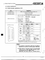
4. PRESTART. U,P PROCEDURES
(1) Switchdetails
"RUN" LED]
@
On......During multitasking
Off*.***.AD51 is not multi tasking. (Will remain off when a single task
is RUN.)
I "RUN-STOP-RESET" switch I
I
RUN/STOP......
0
AD5I-S3
@
d
d
RESET
............
Set to RUN to enable multi tasking to be started
from the input console.
Set to RUN to enablea single task to be started by
typing RUN during
BASIC programming, debuggingetc.
Set t o STOP to stop program execution.
Used to reset an error or to initialize multi tasking.
Error indicator
error code
"INDICATOR RESET" switch
Resets the error code display after the error has been removed.
The error code will remain if the error has not been cleared.
When several errors have occurred, pressing the reset switch will
display consecutive error numbers in the order that they occured.
"M-PROTECT" switch
@
I
as appropriate.
I
Memory protect for system data (the data entered during multi
tasksettingand
BASIC programming) and the user memory.
The memory protect range depends on the
DIP switch settings on
the front of the unit.
For DIP switchdetails,refertoSection
4.3.
/MELSEC
4.. FRE-START UP PROCEDURES
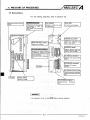
4.3 Hardware Settings
I
.-
4.3.1 Memory protect range
The maximum user program memory capacity is 114K bytes (48K
bytes for ROM
66K bytes for RAM). 48K bytes of theRAM area
may be memory protected in units of
8K bytes.
The system data area (for multitask setting data etc.) may alsobe
memory protected.
To set memoryprotectiontotherequired
area,use the DIP
switches on the front of the unit
as described below:
+
(1) Memoryprotect area
Areas
marked
memory protected.
YHn
1
7FFFn
Channel
0
in the
memory
maps below can
be
Common area
~ F F F H(system data area)
0 4FoOt1 to
6oo(k to 6 7 F h (user workarea)
Channel
1
User memory area
Channel
2
Channel
3
Channel
d
FFFFn
RAM area when ROM is installed.
(1) The memory protect DIP switch number is shown as
memorymap.
0to 0 in the above
(2) Thememory protect DIP switch numbers for a given RAM address range
remain unchanged when ROM'is loaded although the channel number has
changed from channel 1 to 2 or from 3 to 4.
4-5
IB (W 6 6 1 6 9 4
4. PRE-START UP PROCEDURES
(2) Memoryprotect range
-
,-
Protected
RAM
address
ranges
are shownbeloy. The WP
switch is on when the lever points to the right, this is marked m
on the switch cover.
I
DIP Switch Details
.
,
Number
sw1
to
- SW6
- sw7
to
- sw12
- SW13
to
- SW18
Memory addresa
1
SW2
*
Memory Protect Range
sw3
sw4
I
SW5
SW6
sw7
1
1
3
1
4FOOu to 4FFFu
8000~to 9FFFH
1
3
AOOOu to BFFFu
1
3
COOOH to DFFFu
2
1
4
I
8000~to 9FFFu
2
4
AOOOu to BFFFu
2
4
COOOH to DFFFu
I
I
SW8
sw9
SW10
~
SW11
Unused
sw12
SW13
(1) BASIC program address data and multi task setting
data is stored in the system data area 4FoOn t o 4FFF"
(256 bytes).
Setmemoryprotect
with SW1 afterstartingmulti
tasking.
I
'b
(2) SW1 must be set to OFF when the system data area
data has been stored to ROM.
(3) Switching the memory protect keyt o ON protects all
areas defined by the DIP switch settings.
(4) Keep the memory protect switch
program writing and editing.
OFF during BASIC
(5) The RAM areas marked @ and @ on the preceding
pageand the user work area cannotbememory
protected.
-
n
W
4. PRE-START UP PROCEDURES
4.3.2 Consolechannel
DIP switch SW16 determines which of thetwo channels, CH1 and
CH3 is to be used for the programming console.
When the VT-220 is used SW16 should be switched OFF defining
CH3 (RS-232C)as theprogramming console port.Whenthe
GPP/HGP is used the switch is generally switched
ON defining CH1
(RS-422) as the programming console port. (RS-232C may also be
used)
>IPSwitchDetails
CHl
(RS-422)
SW16
m
CH3
(RS-23X)
General-purpose port
VT-220 (GPP/HGP)
POINT
I
The console settingswitch is valid after the AD51 is
powered up or reset.
When the console settine,bs
beenchanged,reset
the
..
AD51.
I
4.3.3 terminal resistor
A terminal resistor is fitted to prevent distortion of the transmission signal waveform. When a number of AD5ls are connected
togethervia anRS-422 link, the two endstationsshouldbe
set
with"terminal resistor present", theremainderwith"terminal
resistance absent." DIP switches SW14 and SW15 are used to set
the terminal resistance as shown below.
DIPSwitchDetails
SW14
SW15
Position Position
ON
OFF
SW15
OFF
POINT
I
Bothswitchesshould
4-7
Description
With terminal resistor
ON
SW14
5
1
Without terminal resistor
beeither onor
off.
IB (NA) 66189A
4. PRE-START UP PROCEDURES
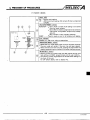
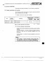
4.3.4 Setting system data transfer
A
1
Set the DIP switch SW17 to ON or OFFas
indicatedbelow
depending on whether or not the system data is transferred from
the ROM of channel 1 to the systemdata area at power on.
lswIl
DIP Switch
Podon
sw17
8oo(k to
D.tr
8oosw
...
n/
Description
Specificpattern
Systemdata is transferred from
channel 1 addresses 8000~to
~ O F F Hto
system
data
area
addresses ~ F W to
H ~FFFH.
Unspecificpattern
Not transferred.
Specificpattern
Not transferred.
Unspecificpattern
Not transferred.
OFF
When the system data exists in channel 1 address range 8O0OHto
~OFFH,
data in 8O0OHto 8004~ in
isa specific pattern to indicate that
the system data exists.
I
SW17 must be set to ON when the system data has been
stored on ROM and set to OFF when not stored on ROM.
4-8
I
IB INN 661S3-A
4. PRE-START UP PROCEDURES
IMPORTANT
I
'
:
-r
i
I",,.:
(1) Before ROM is installed, the shortingpin must beset in
accordance with the ROM type used.
(2) After ROM has been installed, setting the shortingpin
t o RAM may clear the battery backed data.
(3) ROM installation
ROM should be installedafter setting the shortingpin
in accordance with the ROM type used.
(4) ROM removal
After ROM has been removed; the shorting pin should
be set t o RAM.
POINT
1
(1) RAM isbuilt into theunit, there is no need
to loadRAM
into either socket.
(2) The correctdirectionofthe
"blip" on the ROM is
indicated on the ROM socket.
(3) ROM may be loaded into either
socket and ROM sizes
(27128, 27256) may be mixed providing the address
ranges are noted.
(4) WhenROMisinstalledsome
RAM address ranges
change.(For details, refer to Section 3.4.)
(5) Cover the EPROM window .after it hasbeen
rammed.
prog-
(6) Ensure that ROMs are correctly stored and protected.
(7) Keep the ROM away from static electricity-use antistatic foam where possible.
(8) The shorting pin is factory-set t o RAM (RAM.A and
RAM.6 connectors).
(9) Channel 1 shortingpins
channel 2, RAM.6.
4-10
are marked RAM.A and
IB lNAi 66189A
4.,
,
._.
4
,..,.,. - .
I...
-..-.
.
.
,.
..
,
.,
.
.....
,_"I
4. PRE-START UP PROCEDURES
4.3.6 Loading the battery
The battery is disconnected before leaving h e factory to prevent
unneccessary battery consumption. The battery plug should be
connected to pins CON7 on the circuit board before the AD51 is
used.Thered
wireispositive
and theconnectoriskeyed
to
prevent wrong connection.
4-7 1
IB iNAl 66189A
5. WIRING
5. WIRING
5.1 Wiring Instructions
All AD51 external wiring.shouldbeprotected
against noise.
(1 ) Keep cables carrying data at least lOOmm(3.94inch) away from
maincircuitwiring,highvoltagecablesand
PC input and
output wiring.
(2) Ground shield wires or cable shields
(3) Use M4 solderlessterminals
terminal block.
at one point only.
for connection to the RS-422
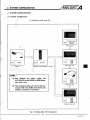
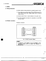
5.2 RS-232C Connection
RS-232C connection
AD51
External
equipment
FG
1
Fig. 5.1 RS-23X Connection Diagram
A maximum of 32 stationsmay
be included inthe
multidrop
system
with an overall link distance of
-
-
",
,
.. ./.-,
,
I. ._-.-..
. . -. .. ..
. .
.
1..
. , ., .
"
., .,.
*.
5. WIRING
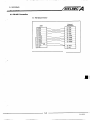
5.3 RS-422 Connection
(1) RS-422 connector
External
equipment
AD51
...
.
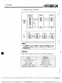
5. WIRING
(2) RS-422 multidrop connection.
I
equipment
I
I
AD51
I
I
AD51
External
equipment
as
master
station
c
AD51
as
master
station
I
POINT
I
A maximum of 32 stations may be included inthe
multidropsystemwith
an overall
link
distance
of
500m(547Yd).
RS-422 multidrop cabling should conform
I
1
to the following specifications.
Item
!5peiitionr
Cable type
Shieldedcable
Conductorresistance(20.C)88.0Q/km
resistance
Insulation
strength
Dielectric
Electrostatic capacity (1kHz)
Characteristicimpedance(100kHz)
I
I
C
or less
10,000MQ.km or less
500V DC for 1 minute
GOnFlkm or less on average
110
f 1on
I
I
I
A
-
6. AD51 PROGRAMMING NOTES
6. -1.
BROORA"
NOTES
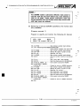
6.1 BASIC Progrpm Address Data
i
The following information must be specified before a GPC-BASIC
program can be written: program number, programhead address,
program last address, additionalprogram head address, work
area head address, and channel. For further details on setting the
data, refer to AD51 OperatingManual.
The following table indicates the function of each of the addresses. Before the
BASIC program can be written a BASIC text area must be defined as well as an
interpreter work area. The operating system automatically asigns the additional
program head address dependingon how much of theBASIC text area is vacant.
kern
Description
Programnumber
BASIC text number (1 to 8 )
Programheadaddress
The first address of the BASIC text area ( 8 0 0 0 ~onwards)
The last address of the BASIC text areaProgramlastaddress
I
Additional program
headaddress
Headaddressofvacantarea
in BASIC text area.
(Automatically set by the O S . )
work Blea head addreJs
Workareaused
I
Channel
for BASIC interpreter.Fixed to 256 bytes.
(Not available for user)
Channel for the BASIC text
(1) Direct variables (A to
work area.
Z)are allotted in the BASIC interpreter
(2) Use the address range DOOOH to FEFFH for @ array variables
andindirectvariables.
The hatched areas intheexample
below may not be used.
Example:
Channel 2 (8O0OHto FFFFH) data has been set as follows:
1.address
Program
head
8000~
2. Program last address
CFFFH
3. Additional
program
head
address
AOCBH
4. Work area address
head
FFOOH
5. Channel
2
BASIC text area
E:;$1
-+-
FFOOH ,
FFFFH
I
BASIC interpreter
work area
6. AD51 PROGRAMMING NOTES
-
(3) The work area must comeafter the textarmand theworkarea
head address must have 00 in the two least significant digits.
256 bytes are usedfor theBASIC interpreter wortarea starting
workat the
area
address.
head
(4) When two or moretasks are written in thesame channel make
sure that the program areas and BASIC interpreter workareas
do not overlap each other.
a) Program data will becorrupted
areas.
in overlappingmemory
b) Multitasking results will be invalid if the BASIC interpreter
work area for a given task is overlapped by program data
from adifferent task. Independent runningofthat
task
however is valid.
BASH: Rogrcnn Addresses
Correct
example
Task
Programheadaddress
Programlastaddress
Additional program head address
Work area headaddress
Channel
TASK 1
TASK 2
1
2
8000~
BOOOH
AFFFH
DFFFH
A ~ ~ C H-51 H
FOOOH
F800n
1
1
Memory Map
BASIC text area (task1)
BASIC text area (task 2)
DFFFH
BASIC interpreter
work area (task
1)
BASIC interpreter
work area (task 2)
FOOon
FFFFH
Overlapping
program
area
Overlapping
interpreter
work
area
Task
Programheadaddress
Programlastaddress
Additional program head address
Work area headaddress
Channel'
1
8000~
AFFFH
A74Cu
FOOOH
1
1
Task
8oooH
Programheadaddress
AFFFH
Programlastaddress
Additional program head address A74Cn
H)wH
Work area head address
1
Channel
2
8m
AOOOH
DFFFH
8851H
F800~
1
BASIC text area (task1)
Overlapping area
BASIC text area (task 2)
BASIC interpreter
work area (task1)
BASIC interpreter
work area (task 2)
2
BoooIl
DFFFH
-51 H
ff
BASIC text area (task 1)
DFFFH
H)OOH
1
FFFFH
BASIC text area (task 2)
BASIC interpreter
work area (task1)
BASIC interpreter
work area (task 2)
._*
n
.-
/MELSEC
&AD51 PKOGRAMMING NOTES
6. AD51 PROGRAMMING NOTES
(5) When the system data is stored onto ROM, the program head
addressmustbe
81OOH or a subsequentaddressbecause
addresses 8O0OHto 80FFH of channel 1 are used as a system
dataarea.
Setting the program head address between 8O0OHand 80FFH
will corrupt the BASIC program and disable normal program
execution.
System data area
User memory area
to
FFFFH
L
I
Channel 1
6. AD51 PROGRAMMING NOTES
Witiuns
6.2.._
*,
a
.
There
are
4 types. ofeBASK program
execution
formats:
(I)
Program runs .once after power on.
( 2 ) Program runs continuously after power on.
(3) Programruns after an interrupt signal from the
(4) Programruns at presetintervals in real time.
PC CPU.
6.2.1 Program runsonce after power on
Write the BASIC program so that "END" is executed as the final
instruction and set the task start condition to "POWER ON".
Task
runs
once after
on
power
I
Set rnulti
task
start
"POWER ON".
c
condition to
I
BASIC program
1
END
6.2.2 Program runscontinuously afterpower on
Writethe
BASIC programusingthe
"GOTO" commandto
continue program execution and set the task start condition to
"POWER ON".
e
rnultitaskstart
"POWER ON".
conditionto
BASIC program
Executionreturns
toline
6-4
XXX.
IB INAI 6618S-A
C
-
6. AD51 PROGRAMMING NOTES
6.2.3 Program runs after an interrupt signal from
the fX CPU
Set the task start condition to "CPU INT" ( W U interrupt). The
program is then run when the rising edge of the AD51 interrupt
signal is received from the PC CPU.
For programming information see Section 7.4.
(1) Write the BASIC program so that "END" is executed as the
final instruction. When '!END" is executed the AD51 interrupt
condition is reset. The interrupt program will not run
again
until the rising edge of the AD61 interrupt signal is received
from the PC CPU.
signal from
CPU
"PC
CPU
PC
multi task start condition to
interrupt".
BASIC program
+
END
PC CPU interrupt reset
(2)Only one task may be defined as PC interrupt start. More than
one will generallylead to "ORST" error.
6.2.4 Program runs at preset intervals in real time
Select starting condition "REAL TIME INT" (real time interrupt).
The real time interrupt interval (i.e. the time between interrupt
signals) should be.tonger than the total time taken for the interrupt
program to reach the END instruction including the time required
by other tasks. An "ORST" error is detected if a second real time
interruptsignal isgivenbeforetheinterruptprogram
has executed its END command.
POINT
1
For tasks other than the one started by the interrupt signal
from the PC CPU (Section 6.2.3), any system subroutine
must not be executed t o access the PC CPU within five
seconds after the PCCPU is run.
A PC down error will occur if the system subroutine is
executed within five seconds.
r--
6-5
I6 lNAi 56189-A
A
6. AD51 PROGRAMMING NOTES
6.3 Notes on the Use of BASK Commands
6.3.1
n
Key input mnmands
Key inputs (INPUTand INKEY commands) to the AD51 via one
channel (asspecified bythe ZlDV command) should onlybe made
to one task.
Since tasks are executed
in order of task numbers, any data keyed
in to a task canonly be readat certain intervals.If a key is pressed
and more than one task is waiting for data from the specified
channel, onlythefirst
task to execute the INKEY or INPUT
instruction will read the key input.
The other tasks will then continue waiting until a key is pressed
while they are being run.
Task 1
Task 2
100
REM
"TASK 2"
to
500 ZlDV 1
510
B=INKEY
"TASK 1"
to
200 ZlDV 1
210 A=JNKEY
to
n
L"'
100
REM
to
Example: When both task 1 and task 2 are waiting for key input
from channel 1, pressing a key will only write data to
one of variables A
or B.
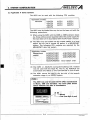
6.3.2 Printing commands
The printingcommands are"PRINT"
-7
and "LPRINT".
(1) Differencebetween PRINT and LPRINT commands
[PRINT]
r
i
Used when the printer is connected to the console channel
(channel 1or 3 set With'DIP switch16) or thechannel specified
with ZODV.
[LPRINT]
Used when the printeris connected to thechannel specified in
the printer setting.
(2) Sharing of a single printer between
'
tasks.
When severaltasks are sharingthe use ofa printer ensure that
interlock flagsare provide4
'._
in the workarea to prevent two or
more tasks attemptingto access the
printer
simultaneously.
6-6
h
IB INN 661ESA
/MELSEC
6. AD51 PROGRAMMING NOTES
4 AD51 .PROGRAMMING NOTES
(3) Note that with printers that use the CR code (ODH)to initiate
printing (KGPRE, K7PRE etc.), writing a comma (,I after the
statement in the PRINT or LPRINT command, stops the AD51
from sendingthe CR code.
Printing is thereforenotinitiated.
(4)Notes on the
use of the KD51PR
The KD51PR may beconnected to either of the two AD51
RS-232C ports. When using the KD51PR note the following:
(a) The KD51PR will print
if data is sent from the AD51
while it is printingorduring
paper feed. This may be
avoidedbyusingtheprogramshown
in Example 2.
Example 1 shows a program which repeatedly prints the
letters "ABCDE" andtheresultant
KD51PR printout.
'I?"
____
L P R l ~ T~ABCDE,,
I
I
I
I
I
I
I
I
I
8
I
!
I
r
110 LPRINT
120 GOT0
1
Print
>i: S 03,------
control code 0 3 is
~ sent from AD51.
I
1-
i
!
I
I
I
L--UDon execution of line 120. execution I
returns toline 100. Data is continuously i
written to the KD51PR while it is still
printing.
I
,
I
!
I
I
data and control codes (CR code, LF
code)are sent fromAD51.
ABCDE
?A?B?D?
?
?E?
?E??D?
?D?E??A?C?E?
6-7
IB INN ffi1ES-A
6. AD51 PROGRAMMING NOTES
(b) When the2K buffer isset to OFF in theKD51PR, any string
of characters sent which is more than one line long will
lead to an overrun error when the LF code is given. (The
receive .buffer is 32 characters long). See below:
100LPRINT
"ABCDEFGHIJKLMNOPQRSTUVWXYZABCDEF"
23(characters)-
Toovercome this, write a comma (,) after the PRINT
statement to stop theLF code from being given as below:
-
n-
'
I
4
100 LPRINT "ABCDEFGHIJKLMNOPQRSTUVWXYZABCDEF,"
6.3.3 CRT displaycommands
Any commands addressed to a CRT on a given channel should
come from one task only.
There is no management of display commands between
tasks.
[CRT display commands]
r
CLS,ZCON,ZCOFF,ZNOR,ZCRV,PRINT,LOCATE
POINT
Any program controllingthe display on oneCRT should be
written in onetaskonly.
6-8
IB INAi 66189-A
r
-
6. AD51 PROGRAMMING NOTES
6.3.4 OPEN and CLOSE commands
Note the following precautions when using the
OPEN and CLOSE
commands.
(1) The channel specified as that for the console by DIP switch
SW16 and the channel selected for the printer on the printer
setting screenare automaticallyopenedbythe
AD51 OS.
The communication mode f o r other channels must be set in
the user programusingthe
OPEN command. These two
channels default to closed.
(2) The OPEN command is used to specify the communication
control at the RS-232C or RS-422 port. 'It'also initializes the
AD51 sendandreceivebuffers.
Executing this command thereforere-defines the communication mode for the specified portand clears both AD51 buffers
at that port.
(3) The CLOSE commandinitializesthe
AD51 communication
control and buffers in the same way as the OPEN command
however in this case the port is left in a read/write disable
state.
r
I POINT I
Before
using
the CLOSE command, ensure thatthe
transmit buffer is empty be using subroutine "STC". Data
will be lost if the buffer is initialized whileit still contains
data.
_ _ _ _ _ _ _ _ _
~
(4) OPEN and CLOSE commands are common to all tasks.
Therefore, any channel opened
by one taskcanbe used in
subsequent tasks without having t o repeat the OPEN command.
6.3.5 2 commends
The ZMOV, ZRD1,ZRD2, ZWRland ZWR2 commandsarenot
available for AD51, PC CPU transactions.
Access to the PC CPU data is via system subroutines.
For details refer to Section 3.2.2.
..
_,.
6-9
IB INAl 66189A
6. AD51 PROGRAMMING NOTES
6.4 Transmission Commands to External Device
,n
r
The PRINT, LPMNT andSWB commands are used to transmitdata
the
external
device.
from
AD5l’s
RS-422 or RS-232C to
1
,T
d
Any transmission command is complete when transmission data is stored to the transmissionbuffer.
Use system subroutine
STC to check that thetransmission
data hasbeensent to the external device.
6.4.1 PRINT command
(1) The channel used is determined by the console channel (set
with DIP switch 16) or ZODV command.
f
(2) Data transmitted depends on thePRINT command designation
form as described below:
P r d n g
Designation
Value of expression(variable)isconvertedintoa
6-digitdecimal
ASCII codeandtransmittedtothe
externaldevice.
Expression
(variable)
Value of expression(variable)isconvertedintoa
4-digit hexadecimal ASCII code and transmitted to the
externaldevice.
$ expression
(variable)
(variable)
. expression
Value of expression (variable) is converted into a real
ASCII code and transmitted to the external device.
(variable)
Value of expression(variable)isconvertedintoa
decimal ASCII code of specified digits and transmitted
to the external device.
# expression
*
n
Value of expression(variable)isconvertedintoa
2-digit hexadecimal ASCII code and transmitted to the
externaldevice.
? expression
____
L
(variable)
Value of expression (variable) is regarded as an ASCII
codeandtransmittedunchangedtotheexternal
device.
expression
(variable)
(Character string
variable)
Data stored in character string variable is regarded as
an ASCII codeandtransmittedunchanged
to the
externaldevice.
(3) The PRINT command maybe used with ASCII codes OOHt o FFH.
Note that OOH and ODH are transmitted as indicated below:
Whentransmissiondatais
When transmission data is
OOH, ODH is sent.
ODH,
ODH and OAH are sent.
The following program should be written when sending
ODnor ODn and OAn by the PRINT command.
ODn: PRINT
*O,
OD., O h : PRINT
$D
*
6-10
IB (NAJ 66189A
/ME~SEC
6. AD51 PROGRAMMING NOTES
6. AD51 PROGRAMMING NOTES
6.4.2 LPRINT command
i
.
(1) Transmitsdata
fromthe
channelspecifiedontheprinter
setting screen.
The LPRINT and LLIST commands cannot be used if NOTHING
hasbeen selected for the printer type.
(2) Data transmitted in accordance with the LPRINT command
designationis as indicated in Section 6.4.1.
(3) Data transmitted by the LPRINT command is as indicated in
Section 6.4.1.
(4) The LPRINT command is not controlled on
a task basis.
6.4.3 System subroutine SWB
(1)Transmits
channel.
data ofthespecifiedlengthfromthespecified
(2) The transmission time can be set in incrementsof 10ms.
A time-outoccurs if transmission is not completed(data is not
stored tothetransmissionbuffer)withinthetransmission
period.
The error status and untransmitted data byte length can be
read.
(3) Transmission data is storedto the AD5l’s commonarea 6O0OH
to 67FFH.
Data in OOH to FFH is regarded asanASCII
unchanged.
6-11
codeandsent
IB INN 661-
6. AD51 PROGRAMMING NOTES
6.5 AD51 and PC CPUReset
m
The following explains theeffects of resetting theAD51 and thePC
CPU.
_.
rn
\._
(1) AD51reset
J
operation
1) The AD51 processes its programsas though the powerhas
beenswitchedon.
With multitask start alreadyset.... Executes multi task.
Withoutmulti task start *.*............Displays themode
select menu on theconsole.
2) All the AD51 general-purposeinputsareswitched
3) During reset, there is no
off.
accessing of the PC CPU.
r
j
.-
4) There is no signal by which the PC CPU can know that the
AD51 hasbeen reset.
5) Any
or
(TO] instructionsexecutedbythe
whenthe AD51 is reset will be invalidated.
PC CPU
(2) PC CPU reset operation
1) Allthe
AD51 general-purpose outputs are switched off.
2) Resetting the PC CPU disables access by theAD51 to thePC
CPU for about five secondsafter the PC CPU is set to RUN.
If the PC CPU is accessed during this period, "PC DOWN
ERROR" or"TIME OUT ERROR" isdetected.
6.6 Notes onBASIC Programming
(1) Before making additions or corrections to the BASIC program
or changing the program to its final format with the
RUN or
COMPILE command, set the "M-PROTECT" switchto OFF.
(2) Beforeexecuting
commands.
multi task, remove all STOP and BREAK
(3) Always RUN or COMPILE the BASIC program after it has been
completed.
The RUN or COMPILE commands change the program into a
format suitable for multitasking. If the program is not formatted the CPU may misoperate. Remember to RUN or COMPILE
programs before writing them to
ROM.
n
q-*
w
7. COMMUNICATION WITH PROGRAMMABLE CONTROLLER CPU
I .
7. COMMUNlCATlON WITH PROGRAMMABLECONTROLLERCPU
The AD51 occupies 48 I/O points and is provided with 13 digital
inputs and10 digital outputs as well as a 3K word buffer memory.
The following section describes communication between the PC
CPU and the AD51. It is assumed that the AD51 is located a t slot 0
and 1 of the mainbase unit andthat any BASIC program is written
in channel 1.
7.1 General-Purpose I/O Readwrite
The AD51canaccess the general-purpose I/O immediately and
continuouslyusingthe
"PEEK" and "POKE" commands.This
eliminates the need to use the data memory read/write system
subroutines which are only processed when the "END" or "COM"
instruction is executed in the PCCPU.
Output Y29 from the PC CPU can be usedas an interrupt signal to
the AD51,see Section 7.9.
7-1
IB lNAl 6618SA
7. COMMUNICATION WITH PROGRAMMABLE CONTROLLER CPU
7.1.1 General-purpose I/O addremas
The general-purpose UO assigned tothe AD51 are accessedvia the
following addressesin the userworkarea:
1
L
Bit ConRgumth Command
Address 6 9 4 0 ~
8 7 B6 8 5 84
I!
Address 6 9 2 0 ~
I
Input
POKE
1
-q.c
I
x19
XlA
I
+
X16
x1c
v
6800~
Address
6820H
Address
8 7 B6B5 84 8 3 8 2 B1 BO 1B71661B51841B31B21BllBO[
A
Reserved for
the OS.
PEEK
3utpu1
111
-
L
I
\-
Y26
Y27
Y28
Y29
Table 7.1 General-Purpose I/O Data Configuration
7-2
IB INN 66169-A
7. COMMUNICATION WITH PROGRAMMABLE CONTROLLER CPU
7.1.2 Write to general-purpose input
.
To wrote to a specified general-purpose input the appropriate bit
in the relevant byte of memory must beset or reset. The memory
addresses for general-purpose inputs and outputs
are given in
Section 7.1.1.
This section describesthe direct accessing of general-purpose
110
data using thePEEK and POKE commands. The system subroutine
"SADR" may alsobeused
to access this data but system
subroutines are only processed after the "END" or "COM"
instruction has beenexecuted in the PC CPU.
Write to general-purpose inputs
1
Read ONlOFF data of generalpurpose inputs from user memory
addressesgiven in Section 7.1.1.
1
1
1
+
Switch input on?
Logical OR operation with appropriate bit of 'dummy" byte set to 1.
Logical AND operation with
appropriate bit of 'dummy" byte set
Write to general-purpose input area.
L
-
-
-
I - - --When
r------J
-Write
- -to- workarea.
&
general-purpose I/O data is required for use in the work area.
Completion.
7-3
18 lNAl66183-A
7. COMMUNICATION WITH PROGRAMMABLE CONTROLLER CPU
[Programexample]
m
Inputs X13 and X1B are turned on and off respectively and the
resultant on/off condition is stored in head addresses 6O0OHand
m1H.
I
c,
.
>
I
(1) Program to switch on X13
100 A=PEEK( $ 6000) ....... Reads address 600011from the common
area (This
byte is all 'Os).
110 B=Aj $ 08 ................Executesalogical
OR operation with address
6000~ and
a "dummy" byte containing the binary
representation of 8 as follow:
Bit pattern
Address 6000~
82
OR result
The result
120 POKE S692O.B
00000000
00001000
00001000
is written to variable E.
f\L
......... Variable
B is written to address 6920~ (i.e. the
user work area reserved for accessing the general-purpose VO).
130 POKE $6000, B ......... The result is also written to address
600011.
140END
switch
to
(2) Program
off X1B
-f
W
100 A=PEEK( $ 6001)....... Reads address600111from the commonarea (This
byteisall '0's).
110 B=A&$ F7 ............... Executes a logical AND operation with address
6000~ anda dummy byte containing the binary
representationof F7 as follows:
Bitpattern
6000~ Address
result
00000000
F72
11110111
00000000
AND
Theresultiswrittenintovariable
E.
.........Variable
B is written to address 6940~ (i.e. the
user work area reserved for accessing the general-purpose 110).
130 POKE $6001, B .........The result is also written to address 6001~.
140END
120 POKE $6440,B
*: X1D to 1F cannot beturnedon/offinthe
BASIC
program. Thevalue marked * in line 110 of (2) may also
be 17" (bits 5 to 7 = 0 ) . If AND operation is performed,
the sameresult is obtained.
7-4
IB (NAI ffi184A
7. COMMUNICATION WITH PROGRAMMABLE CONTROLLER CPU
7.1.3 Read from general-purpose output
A similar procedure may be used to read the general-purpose
outputs using thelogical AND operation. The work
area addresses
are given in Section 7.1 -1, Note that bits2 to 7 of address 6820Hare
reserved for the operating systemand should bemasked.
[Programexample]
Program for ON/OFF monitor of Y20 to 27
100 A=PEEK( $6800)................... Reads address 6800~to variable A.
110B=1 ....................................
Variable B set t o 1.
120 FOR 1=0 TO 7
130 IF (A&B)#O PRINT "ON" ;
GOTO 150 ............................
Performs AND operation of variable A
140PRINT "OFF"
150 B = B * ~ ...............................
160 NEXT I
170 END
7-5
and variable B, and if relevant bit is on,
displays"ON".
Shifts the contents of variable B one bit
to the left.
IB (NAl 6618SA
~
.....
... -
.....
7. COMMUNICATION WITH PROGRAMMABLE CONTROLLER CPU
7.2 ReadMrite of Buffer Memory
The buffer memory can be accessed by both the BASIC program
and the sequence program.
A maximum of 3K words can be transferred with one instruction.
7.2.1Read/writewith
-
n
BASIC program
-
The following system subroutines are used to access the buffer
memory.
For details refer to the GPC-BASIC Supplementary Handbook.
Read from buffer memory
SR2
Write to buffer memory
sw2
Read/write retry time
sc2
C
1
-
The buffer memorv cannot be
accessed bv the AD51 if the PC CPU is alreadv
or
instruction:
this
Incase
the
AD51
will
ret;
executing a
communication according to its retry time setting.
The retry time is set at 10ms unless changed using the SC2 system subroutine.
[Programexample]
( 1 ) Program to read 256 words from buffer memory head address
200H to AD51 memory headaddress FOOOH.
100 A= $ EO00 ............................
110 A(O)= $200..........................
120 A ( 1 ) z $ FOOO ........................
130 A(2)= $ 100 ..........................
140 B=CALL(O, S 8000, 1, A) .........
150 IF S#O PRINT"ERROR",
B; GOTO 140.........................
160 END
4
.
Indirect variable head address
Data source
buffer
memory
head
address
Datadestinationheadaddress
Number of words
System subroutine SR2 reads buffer
memory.
Checks for errors in
T
L
SR2 execution.
(2) Program to write data from work area addresses E700~to
E 7 7 L in theBASIC program to buffer memoryaddresses 3 5 0 ~
to 38F~.
100 C= $ E100 ............................
110 c(o)= $ 350 ..........................
Indirect variable head address
Data destination buffer memory head
address
Data
source
buffer
memory
head
address
0............................
130 c ( 2 ) = $ 4words
data
of Number
140 D=CALL(O, S 8003, 1, C) ......... System
subroutine
SW2
writes
data
to
buffer memory.
150 IF D#O PRINT "ERROR",
D; GOTO 140 ........................
Checks for errors in SW2 execution.
120
c(1)=
160 END
$ ~ 7 0 0........................
7-6
.4
kr
'
-
IB IN&! 661ES-A
7. COMMUNICATION WITH PROGRAMMABLE CONTROLLER CPU
7.2.2 Readlwrite with sequence program
Access to the buffer memory from the PC program is via the
and (TOI application instructions.
(m]
Symbol
Description
Usable
DevicoS
nl
16th VO address of theAD51 omitting
the least significant digit.
K. H
n2
Buffer memory headaddress of datasource.
K. H
D
Headdevice number of data destination.
n3
Number of words of data to be read
POINT
T, C,D.
W, R
K, H
I
Notethatthelocationspecificationforthe
AD51 is
different from other special function modules. To specify
the slot location
use the number representing the 16th
I/O
point, omitting the"modules". (So for example, I10 point
120His represented as 1 2 4
Hence, if the AD51 is located atI/O addresses. X60 t o X8F
and Y60 t o Y8F, nl is defined as H7.
[Programexample]
Fig. 7.3 shows a program to read the data from buffer addresses
5OOH to 54FHto data registers Dl00 to Dl79 in thePC CPU. When
X13 turns with system configuration shown in
Fig.7.2.
I
Slot number
6
50
14
2
3
1
I
7
I
A62P
A3
cpu AXlOAXllAX41AX40
Aq51
AY41
AY41
I
X00 X10 X30 X50 X60 Y60 Y90 YE0
to to to to
to
to
to to
YOF X2F X4F X5F X8F Y8F YAF YCF
Fig. 7.2 Module Configuration
.I
I
Fig. 7.3 Buffer Memory Read
7. COMMUNICATION WITH PROGRAMMABLE CONTROLLER CPU
Description
nl
n2
I s I
n3
16th
UO address of the AD51 omitting
the least significant digit.
K, H
Buffer memoryhead address of data destination.
K. H
Head device number of data source
Number of words of data to be written
C
K. H
[Program example]
Fig. 7.4 shows a program to write data from PC data registers0200
to D263 to buffer addresses looHto 13FHwhen X1F turns on with
thesystemconfigurationshowninFig.7.2.
1
I
,
I
I
Fig. 7.4 &rtfer M m o r y Write
t
7-8
.
.
IB (NA) ffi18SA
7. COMMUNICATION WITH PROGRAMMABLE CONTROLLER CPU
7.3 Device Memory ReadMrite
This section explains how the AD51 communicates with the PC
CPU device memory to read present value data and to write new
values.
7.3.1 System subroutines and deviceranges
The following system subroutines are used by theAD51 to access
the PCCPU devicememory.
(1) System subroutine types andfunctions
I
I
Syrtem
Item
Bit
SADR
Word
Bit
Batch
write
Device
nemor
SADW
Word
Bit
Test
During
random
write
1
SADT
Word
Bit
Monitor
data
entry
Monitor
Word
Word
transaction.
Reads data from bit device (suchas Y and M) (for
1 point).
256 points
Reads datafrom bitdevices (suchas Y and M) (for
16 points).
32 words
(512 points)
Readsdata from word device (such as D and R)
(for 1 point).
points
Write data to bit device (such as Y and M) (for 1
point).
160 points
Writes datato bitdevices (suchas Y and M) (for16
points).
10 words
(160 points)
Writes datato worddevice (suchas D and R) (for 1
point).
64 points
Setshesets any specifiedbit device (suchas Y and
M) anddevice number (for 1 point).
2o points
Setshesetsanyspecified
number ofblocksof
sixteen bit devices (such as Y and M) and device
number (for 16 points).
(160 points)
words
Writes data to any specified word device (suchas
Y and M) anddevice numby (for 1 point).
points
Defines the bit device (such as Y and M) to be
monitored (for 1 point).
points+
Defines the word device (such as D and R ) to be
monitored (for1point).
Monitors thedevicespecified
entry.
SADMl
w
PC CPU, AD51
Defines the bit devices (such as Y and M) to be
monitored (for 16 points):
SADMO
Bit
M
Processing
Subroutine
Batch
read
Number of points PC CPU State
in monitor data
STOP
During During
RUN
0
0
0
0
0
0
20 words*
(320 points)
'
2o points
Tabb 7.2 System Subroutines and Functions
Key,
0 : indicatesavailable.
*: When theAl(E), A2(E), A3(E),A l N , A2N or A3NCPU is used, half the number of
points shown above is processed for device X.
When the AOJ2orABHCPU
is used, there is no restriction like above.
7-9
16 INA) f f i 1 8 9 A
7. COMMUNICATION WITH PROGRAMMABLE CONTROLLER CPU
(2) Valid device ranges for device memory transactions are given
below:
The device range depends on the PCCPU module used. See
the corresponding CPU User‘s Manual.
I
word WkeS
Bit Devices
~~~
I
I
Input X
X0000 to XO7FF
Hexadecimal
Timer (presentvalue)
T
TNOOO to TN255
Decimal
Output Y
YOOOO to YO7FF
Hexadecimal
Counter
(present
value)
C
CNOOO to CN255
Decimal
Internal
relay
M
Latch
relay
L
Linkrelay B
relay S
I
I
MOOOO to M2047
Loo00 to L2047
Boo00 to BOBFF
I
I
Decimal
]
I
Decimal
FOOOO to F0255
Specialrelay M
M9000 to M9255
Timer (Contact) T
TSOOO to TS255
Timer (Coil) T
TCOOO to TC255
Counter(Contact) C
CSOOO to CS255
Counter (Coil) C
CCOOO to CC255
Link
register
W
Fileregister R
Hexadecimal
SO000 to S2047Step
Annunciator F
Data register D
Specialregister D
I
1
DOOOODl023
to
Woo00 to WO3FF
ROOOO to R8191
D9000 to D9255
I
I
Decimal
Hexadecimal
Decimal
Decimal
Decimal
Table 7.3 Valid Device Ranges
POINT
I
(1) Bit devices and word
follows.
devicesare
differentiated as
.-..-..X, Y, M, L, S, 6, F, T (contact), T (coil),
C (contact), C (coil)
Word device -.-.T (present value), C (presentvalue), D,
Bit device
W, R
(2) When reading 16 consecutive
bit devices as word data,
the bit device number must be a multiple of 16.
(3) The “0” in the most significant digits of the device
number may be specified
asspaces (204
(4) M and 1 ranges arespecifiedin the PC CPU parameters
however AD51 device memory transactions regard the
two as the same.
(5) Different device ranges apply when using
the AD51
with the AOJXPU. (See A N 2 Programming Manual)
7-10
IB INAJ 6 6 1 8 9 A
7. COMMUNICATION WITH PROGRAMMABLE CONTROLLER CPU
...
(3) Bitlword specification
(a) When a systemsubroutine has been called with "bit"
processing specified, one byte of AD51 memory is used
per bit. This is illustrated below, the least significant bit
indicates the state ofthe specified bit device forboth
reading and writing.
I
1
I
Data to lm
87 B6 B5 84 83
82
I
Read
B1 BO
All turn to "0".
Data to lm Written
87 B6 85 84 83
82
'4
L[l:ON
I
0 : OFF
B1 BO
B1 to 87 data is
ignored.
' +
L[1: ON
0 : OFF
(b) When a system subroutine has been called with "word"
specified, andbit devices are to be processed (i.e. in
batches of 16 devices) then one word of AD51 memory is
used per 16 bits.
This is illustrated below. The head device number is X10
and state of thisdevice is indicated by the
least significant
bit. The states of the next 15 bits are stored i n consecutive
bits from Bit B1 to Bit B15.
815
814
813
612
611
610
B9
X1F X1E X1D X l C
7-1 1
88
67
66
65
84
83
82
X15 X14
X16X13
X17
B1
X18
BO
X10
X19
X11
X1A
X12
X16
IB (NAJ 6 6 1 W
7. COMMUNICATION WITH PROGRAMMABLE CONTROLLER CPU
7.3.2 BASIC program examples
-
h
This seoticm gives some BASIC programexampleswhich
use
system subroutines SADR (batch read), SADW (batchwrite),
SADMB (monitor data entry), SADMl (monitor), and SADT (test).
The programexamples use channel 1.
For details of the system subroutines,
refer to the GPC-BASIC
Handbooks.
'-
(1) Batch readfrom device memory (SADR)
[Programexample
11
Program to read data from 16 points, X100 to XlOF, to AD51
addresses EOOOH to EOOFH as individual bits.
C
100 A= $ FOOO ............................
110
120
130
140
150
160
170
180
190
200
210
Head address for system subroutine INPUT data.
A:O)= $ FF............................
Defines PC station number as host.
A:l)=-"B".............................
Specifiesbitread.
B= $ FOO2 ............................
Sets indirectvariableheadaddress.
$ = " x o 1 w " .......................
Sets head device to be read using character string variable.
c= $ ~ 0 0 7............................ Setsindirectvariableheadaddress.
C(O)=l6 ...............................
Sets the number of points to be read as
16.
C ( l ) = $ E m ........................
Sets
destination
head
address
for
data.
C(2)=60 ...............................
Sets time check period to 60 (600msec).
Z=CALL(O, $8078, 1, A) ......... Calls system subroutine SADR.
IF Z#O PRINT "ERROR",
2; GOTO 190.........................
Checksforerrorsin
SADR execution.
END
LPOINT
I
(1) Whenspecifying the headdevice using acharacter
string variable, define the number of points
t o be read
after setting the head device.
(Reason: The character string variable ovenwrites the
bits at the end of the data
with "0". This would delete
the "number of points" data if this was written first.)
For fullinformation, see Section 2.4.4 in the GPCBASIC Handbook.
(2) The time check period in line 180 should be set in
accordance with the "number of scans required for
processing"given
in Section 3.8 aftertakinginto
account any delays which may
occur due t o other
devices accessing the PCCPU.
h
W
,?
7. COMMUNICATION WITH PROGRAMMABLE CONTROLLER CPU
21
example [Program
. -.
Program to read data from 16 points, X100 to XlOF to AD51
addresses EOOOH to EOOIHin wordunits. (i.e. batches of 16 bits)
100 A= $ FOOO ............................
110 A:O)= $ FF ............................
120 A : l ) = " W " ............................
130 B= $ FOO2 ............................
140 8 $ = " X O ~ O O.......................
"
150 c= $ ~ 0 0 7............................
160 C(O)=1 .................................
170 c(1)= $ EOOO ........................
180 C(2)=60 ...............................
Head address for system subroutine INPUT data
Defines PC station number as host.
Specifies word read.
Sets indirect variable head address.
Sets head device to be read using character string variable.
Setsindirectvariableheadaddress.
Sets the number of points to be readas
1.
Sets destination head address for data.
Sets time check period to60 (600msec).
190 Z=CALL(O, S 8078, 1, A ) ......... Calls system subroutine SADR.
200 IF Z#O PRINT "ERROR",
Z; GOTO 190 .........................
Checksforerrorsin
SADR execution.
210 END
When "bit read" is specified, one byteof AD51 memory is required per bit of data.
8 bits of data.
When "word read" is specified, one byte of AD51 memory contains
See below:
Bit U n b (Exampto 1)
Word Units (Example 2)
87
87 B6 65 84 83 82 B1 BO
XlW
EOOOH
EWH
EW~H
x101
EW2H
x102
EW3H
XlOF
EWDH
X1 OD
EWEH
XlOE
EWFH
All turn to 0.
P-
L ( 10:: ON
OFF
E001~
B6
E5
84
83
82
B1
BO
X104 X103
X105 X102
X106X101
X107
X1
XlOE XlOD XlOC
XlOF
X109 X1
XlOA
X106
7. COMMUNICATION WITH PROGRAMMABLE CONTROLLER CPU
(2) Batch write to device memory
(SADW)
m
[Programexample 11
Program to write on/off data to Y80 to Y9F from the AD51 as
individualbits.
-'
Switch on Y80 to Y8F
Switch off Y90 to Y9F
100 A= $ E800 ............................
110
120
130
140
A:O)= $ FF............................
A:l)="B" .............................
B= $ ~ 8 0 ............................
2
B $ ="y0080" .......................
150 C= $ E807 ............................
160 c(o)=32 ...............................
170 c(1)= $ EOOO ........................
180 c(2)=30 ...............................
1
NEXT
I
Head address for system subroutine INPUT data
Defines PC stationnumber as host.
Specifies bit write.
indirect
Sets
variable
address.
head
Sets
destination
head
device
using
character string variable.
Sets indirectvariableheadaddress.
Sets the number of points to be written
to 32.
Sets sourcedataheadaddress.
Sets time check period to 30 (300msec).
$ EO00
190
D=
200 FOR 1=0 TO 15
data to
be
written
to
addres................ Generates
210 D:l)=l
ses EWOH to EO~FH.
220D:1+16)=0
230
I
240 Z+CALL(O, S W7E, 1, A) .........Calls system subroutine SADW.
250 IF Z#O PRINT "ERROR",
2; GOTO 240 ......................... Check for errors in SADW execution.
260END
1
7-14
-
r
P
L
rn
d
l
IB (NA) 6 6 1 8 9 A
7. COMMUNICATION WITH PROGRAMMABLE CONTROLLER CPU
[Programexample 21
Program to write on/off data to Y80 to YSF from the AD51 as
individualbits.
i
Switch on Y80 to Y8F
Switch off YSO to Y9F
100 A= $ E800 ............................
110
120
130
140
A:O)= $ FF ............................
A : l ) = " W " ............................
B= $ ~ 8 0 2
............................
B $ ="y0080" .......................
Head address for system subroutine INPUT data
Defines PC station number as host.
Specifies word write.
Setsindirectvariableheadaddress.
Sets destination head device using char-
150 C= $ E807 ............................
160 C(0)=2 .................................
acterstringvariable.
Setsindirectvariableheadaddress.
Sets the number of words to be written
170 c(1)= $ EOOO ........................
180 c(2)=30 ...............................
to 2.
Sets sourcedataheadaddress.
Sets time check period to 30 (300msec).
190 @( $ E000)= S FFFF
200 @( S E002)=0
1
.............Generates data to be written to addres-
ses EOOOH
E003~.
to
210 Z=CALL(O, $807E, l.A) ......... Calls system subroutine SADW.
220 IF Z#O PRINT "ERROR",
z; GOTO 210 ......................... Checks for errors in SADW execution.
230 END
When "bit write" is specified, one byte
of AD51 memory is required per bit of data.
When "word write" is specified, one byte of AD51 memory contains 8 bits of data.
See below:
87
87 E6 85 B4 83 82 E1 BO
EOOOH
1
B6
85
B4
83
82
E1
BO
EOOOH
E m l ~
EW2n
E003H
EO~CH
E01DM
w
EO~EH
E01 FH
0 or1
L { 1 : ON
0: OFF
'Only BO is valid and E1 to 87 areignored.
L
7-15
I6 lNAl ffi189-A
A
7. COMMUNICATION WITH PROGRAMMABLE CONTROLLER CPU
(3) Data write to any PC devicedata
memory (SADT)
-
[Program example 11
Program to write on/offdata
devices:
m
to the following random bit
n.
L,
Switchon Y115, switch off M340.
Switch off B24C,switchon
L875.
100 A= $ EO00 ............................
110
120
130
140
150
160
170
180
190
200
210
220
230
240
250
260
270
FOR 1=0 TO3
A(I)= $ E100+1*6
I
Head address for system subroutine INPUT data
character
string
variable
head
.............. Sets
address for destination device.
NEXT I
C= $ E100 ............................
Sets indirect variable head address.
A $ (o)=l'yo1 15" ................... Sets device name "YO1 15".
c:5)=1 ................................
Source data for Y115.
A $ (1)="M0340" .................. Sets device name "M0340".
C:11)=0 ...............................
SourcedataforM340.
A $ (2)="8024C"................... Sets device name "B024C".
c:17)=0 ...............................
Source data for
B24C.
A$(3)="L0875" ................... Sets device name "L0875".
c:23)=1 ...............................
Sourcedatafor
L875.
B= $ E200 ............................
Sets indirect
variable
head
address.
B:O)= $ FF ............................
Defines PC stationnumber as host.
B:l)="B" .............................
Specifies "bit write".
8(1)=4 .................................
Specifies 4 pieces of data to be written.
B(2)= $ E100 ........................
Setssourcedataheadaddress.
8(3)=70 ...............................
Sets time check period to 70 (700msec).
P.
.?\-
"-'I'
280
290 Z=CALL(O, S 8081, 1, 6) ......... Calls system subroutine SADT.
300 IF Z#O PRINT "ERROR",
2 ; GOTO 290 ......................... Checks for errors in SADTexecution.
310 END
.IF'
A
7. COMMUNICATION WITH PROGRAMMABLE CONTROLLER CPU
[Program example 21
Program to write numericaldata
word devices.
D567
W187
--
--
0
R882
751, C49
I
100 A= $ E000 ............................
/
,,.-
0
to thefollowingrandom
1234
Sets indirect variable head address.
110 FOR 1=0 TO3
Character stringvariableheadaddress
..............fordestinationdevice.
120 A(I)= S ElOO+l*7
130NEXT I
0
Sets indirect variable head address.
140 c= $ ~ 1 0 ............................
150 A S (0)="D0567" ................... Sets device name "D0567".
160 @(C+5)=0 ...........................
Setssourcedata
for D567.
170 A $ ( l ) = " R 0 8 8 2 " ................... Sets device name "R0882".
Sets source data for
R882.
180 @(c+12)=1234 ....................
190 A $ (2)="WO187" .................. Sets device name "W0187".
200 @(C+19)=751 ......................
Sets source data for W187.
210 A $ (3)="CN049" ..................Sets device name "CN049".
220 @(C+26)=0 .........................
Sets source data for
CN49.
230 B= $ E200 ............................
Sets indirect variable head address.
240 B:o)= $ FF ............................
Defines PC station number as host.
250 B : l ) = " W " ............................
Specifies"wordwrite".
260 B(1)=4 .................................
Specifies 4 pieces of data to be written.
270 B(2)= $ E100 ........................
Setssourcedataheadaddress.
280 ~ ( 3 ) = 7 0...............................
Sets time check period to 70(700msec).
290 Z=CALL(O, S 8081, 1, B) ......... Calls system subroutine SADT.
300 IF Z#O PRINT "ERROR",
z; GOTO 290 ......................... Checks for errors in SADT execution.
310END
I - I I
I6 INA) 66189.A
7. COMMUNICATION WITH PROGRAMMABLE CONTROLLER CPU
I
REMARKS
1
The data is stored in the
AD51 in the following formats depending on whether
"bit" or "word" hasbeenspecified.
Bit (Example 11
I
E102n
Word (Example 2)
ElOln
IDevice name
E103n
Devicename
E1 0 3 ~
'1"
Data to be Written
K
A
E105n
t
'6"
'7 "
o
I1
Data to be written
Devicename
Data to be Written
E~ODH
"OCH
j
Data to be written
E1l
E
E113n
1l
&
2~
Devim name
ill%
E116H
E117n 0 0 0 0 0 0 0 1
Sets data to be written to
(1 : ON, 0 : OFF).
,
.
7-18
Devim name
Data to be written
E119n
Data to be written
IB INAI 6618S-A
7. COMMUNICATION WITH PROGRAMMABLE CONTROLLER CPU
(4)Definingdevicenumbers
tobemonitored.(Before
a given
device can be monitored using the SADMlsubroutine, it must
bespecified and "entered" using the following
procedure.)
[Programexample
11
Program to specify the following bit devices for monitoring
(i.e. monitor data entry)
X7D Y201
B3A0,T46 contact, C85 coil
I
Sets indirect variable head address.
100 A= $ FOOO ............................
110 A $ = " X 0 0 7 D Y 0 2 0 1 M 0 1 7 8 B 0 3 A O T S 0 4 6 C C 0 8 5 " ~ ~ ~ ~ ~ ~ ~ ~ ~ ~ ~ ~ ~ ~ ~ ~ ~
..... ...........................................
Stores device numbers into work
area.
Sets indirectvariableheadaddress.
120 B= $ E800 ............................
Defines PC station number as host.
130 B:O)= $ FF ............................
Specifies "bit entry".
140 B : l ) = " B " .............................
Sets indirectvariableheadaddress.
150 C= $ E802 ............................
C(0)=6
.................................
Sets the number of points to be entered
160
to 6.
C
(
l
)
=
A
................................
Sets"entry"datahead
address.
170
Sets time check period to50 (500msec).
180 c(2)=50 ...............................
190 Z=CALL(O, $8084, 1, B) ......... Calls system subroutine SADMO.
200 IF Z#OPRINT "ERROR",
Z; GOTO 190.........................
Checks for errors in SADMO execution.
210 END
[Programexample 21
Program to specify the following worddevices for monitoring
(or bit devicesentered as16 consecutivedevicenumbers).
X60 to X6F,T80 to T95 contacts, C183 present value
, w175
R700
D260
I
100 A= $ FOOO ............................
Sets indirect variable head address.
110 A $ ="X0060TS080CN183D0260W0175R0700" .................
..... ............................................ Stores device numbers into work area.
Setsindirectvariablehead
address.
120 B= $ E800 ............................
Defines PC station number as host.
130 B:O)= $ FF ............................
Specifies "wordentry".
140 Bal)="W" ............................
Sets indirectvariableheadaddress.
150 C= $ E802 ............................
Sets the number of points to be entered
160 C(O)=6 .................................
to 6.
Sets "entry"dataheadaddress.
170 c ( l ) = A ................................
Sets time check period to 70 (700msec).
180 c(2)=70 ...............................
190 Z=CALL(O, $8084, 1, B) ......... Calls system subroutine SADMO.
200 IF Z#O PRINT "ERROR",
Z; GOTO 190 .........................
Checks for errors in SADMO execution.
210 END
7-19
...
.
-- . . . . . . . . . . . . .
IB lNAi 6 6 1 8 9 A
-.
__ ..
-
7. COMMUNICATION WITH PROGRAMMABLE CONTROLLER CPU
POINT
I
The SADMO system subroutine (Monitordataentry)
is
used for both bit and word device and, once entered, is
valid for all tasks. Thesesystem subroutine enter the
devices specifiedinto theOS area where theyremain valid
until new ones are entered.
(5) Monitoring of devices (SADM1) specified by the monitor data
entry (SADMO)
[Programexample
11
Program to specifyand
monitor the following bit
devices:
X7D , Y201
B3A0, T46 contact, C85 coil
100 A= $ FOOO ............................
Setsindirectvariableheadaddress.
110 A $ ~ " X 0 0 7 D Y 0 2 0 1 M 0 1 7 8 B 0 3 A O T S 0 4 6 C C 0 8 5 " ~ ~ ~ ~ ~ ~ ~ ~ ~ ~ ~ ~ ~ ~ ~ ~
..... ........................................... Stores device numbers into work
area.
120 B= $ E800 ............................
Sets indirectvariableheadaddress.
130 B:O)= $ FF ............................
Defines PC station number as host.
140 B:l)="B" .............................
Specifies"bitentry".
150 C= $ E802 ............................
Setsindirectvariableheadaddress.
160 C(O)=6 ................................. Sets the number of points to be entered
to 6.
170 C(1)=A ................................
Sets "entrydata"head
address.
180 c(2)=50 ...............................
Sets time check period to 50 (500msec).
190 Z=CALL(O, $8084, 1, B) ......... Calls system subroutine SADMO.
200 IF Z#O PRINT "ERROR",
Z; GOTO 190.........................
Checks for errors in SADMO execution.
210 D= $ E900 ............................
Sets indirectvariableheadaddress.
220 D:O)= $, FF............................
Defines PC station number as host.
230 D : l ) = " B " .............................
Specifies"bitmonitor".
230 D(1)= $ EA00 ........................
Data destinationheadaddress.
240 D(1)= $ EA00 ........................
Data destinationheadaddress.
250 ~ ( 2 ) = 5 0...............................
Sets time check period to50 (500msec).
260 Z=CALL(O, $8087, 1, D) .........Calls system subroutine SADM1.
270 IF Z#O PRINT "ERROR",
Z; GOTO 260 .........................
Checks for errors in SADM1 execution.
280 END
..
7-20
IB (NAI €6189-A
7. COMMUNICATION WITH PROGRAMMABLE CONTROLLER CPU
[Programexample 21
..
-I
Program to specify and monitor the following bit
devices (and
bit devices entered as 16 consecutive device numbers).
I
1
X60 to X6F, T80 to T95 contacts, C183 present value
D260
, w175
, R700
100 A= $ FOOO ............................
Setsindirectvariableheadaddress.
110 A $ ="X0060TS080CN183D026OWOl75R0700" .................
.................................................. Stores device numbers into work area.
120 B= $ E800 ............................ Sets indirect variable head address.
130 B:o)= $ FF ............................
Defines PC station number ashost.
140 ~ : l ) = " w "............................
Specifies "word entry".
150 C= $ E802 ............................
Setsindirectvariableheadaddress.
160 C(O)=6 .................................
Sets the number of points to be entered
t o 6.
170 C ( l ) = A ................................
Sets "entry"dataheadaddress.
180 c(2)=50 ...............................
Sets time check period to 50 (500msec).
190 Z=CALL(O, $8084, 1, B) ......... Calls system subroutine SADMO.
200 IF Z#O PRINT "ERROR",
Z; GOTO 190.........................
Checks for errors in SADMO execution.
210 D= $ E900 ............................
Setsindirectvariableheadaddress.
220 D:O)= $ FF ............................
Defines PC stationnumber as host.
230 ~ : l ) =$ 57 ............................
Specifies"wordmonitor".
240 ~ ( 1 ) =$ EAOO........................
Datadestinationheadaddress.
250 ~ ( 2 ) = 5 0...............................
Sets time check period to 50 (500msec).
260 Z=CALL(O, $8087, 1, D) ......... Calls system subroutine SADM1.
270 IF Z#O PRINT "ERROR",
Z; GOTO 260 .........................
Checks for errors in SADM1 execution.
280 END
The data is stored in the AD51 in the following formats depending on whether
"bit"or"word"hasbeenspecified.
Bit (Example 1)
Word (Example 2)
'
87
87 86 05 E4 83 82 B1 BO
E*ooH
X7D
EAOOH
EA01H
Yml
EAOM
EAOlH
M178
EA02H
EA03H
BJAO
EAOBH
EADW
T48 contaci
W
E A W
c 8 5 coil
EAOSH
H
E A W
EA07H
EAMH
86
85
E4
83
82
81
BO
I
X60 IO XSF
I
I
lDm
l
W lo 195
contacts
C183 present value
)wm
EAOSH
EAOAH
7-21
IB iNAi 66189A
7. COMMUNICATION WITH PROGRAMMABLE CONTROLLER CPU
7.4 ExtensionFileRegister
ReadIWrite
The following procedures are used to access the extension file
registers from the AD51.
7.4.1 System subroutinesandfunctions
The following system subroutines are used by the AD51 to access
the PC CPU extension file registers.
(1) System subroutine types and functions
ttem
System
Subroutine
Number of Points
Procebsed per
PC CPU, AD51
Transaction
Processing
SAER
Reads data from extension file register (for
point).
1
Batch
write
SAEW
Writesdatatoextensionfileregister(for
point).
1
Test
(during
random
write)
SAET
Writesdatatoanyspecifiedextensionfile
register(for 1 point).
Batch
read
Monitor Defines the extension file register to be moniSAEMO
data entry tored.
Monitor
SAEM,
Monitors the device specified in monitor data
entry.
PC CPU State
STOP
During
RUN
0
0
0
0
10
0
0
20
0
0
0
0
64
\
Key
0:
During
Indicatesavailable.
Table 7.4 SystemSubroutines and Functions
(2) Extension file registers
The empty area of the memory cassette has been defined for
use as extension file registers in groups of 8K points (16K
bytes).
Touse this area as extension file registers, the SW[IIGHPUTLPC-FN1 utilityprogrammust
be stored tothemicrocomputer program area of the memory cassette.
The utility program automatically defines the empty area in
blocksof 8K points as extension file registers.
For full information on the utility program,
see the SW[IIGHPUTLP-FN1 OperatingManual.
I
7-22
IB INN 6618SA
(3) Extension file registerblocknumbers
When the empty areaisdefinedasextensionfileregisters,
block numbersareautomaticallyallocatedingroupsof
8K
points in accordance with the used CPU, memory cassette,
program capacity,etc.asshown
below:
T
Parameter
T K set value
Sequenceprogram
Microcomputer program
-
Empty
M e m o qI
cassettc?
capacinI
Block n
Extension
file
register
Memory cassette
empty area
8K points X
9 blocksmax.
to
Block 2
Block 1
-
Sampling trace
Statuslatch
Fileregisterblock
0
Comment
Block 28
Extension
file
register
to
Block 11
Block 10
For more information, see Section 4.8.2 in the SW[:IGHP-UTLP-FNl OperatingManual.
7-23
IB INAJ6 6 1 8 9 A
7. COMMUNICATION WITH PROGRAMMABLE CONTROLLER CPU
(4) Validblock
numbers
m
The following block numbers may be usedin accordance with
memory
the
cassette and CPU used.
-.
n
-.e
Memory
Valid
Cassette
I
A3NMCA-0
A3MCA-0
A3NMCA-2
A3MCA-2
I
16K bytes
Invalid
I
A3HCPU
I A2iE).
. .. A3iE)CPU
. .
Invalid
Invalid
Invalid
Invalid
Block 1only
I ASNMCA-16 I
I ABNMCA-24 1
I AQNMCA-40 1
A3MCA-18
I
I
16K bytes
Block Numbers (RAM/ROM operation)
AZN, A3NCPU
A3NMCA-56
I
I
1
96K bytes
144K bytes
I
~
-
I
I
1
I
Invalid Block Numbers
Invalid
Block 1only
Up to block 3
Up to block 3
Up to block 5
Up to block 5
Up
Blocks
to block
10, 11
5
Up to Mock 5
Blocks 10,11
Up to block 5
Blocks 10,11
Up to block 9
Up to block 9
Up to block 9
I
Blocks 10,11
Blocks 10 to 28
Up to block 9
144K bytes Blocks
Up to 10
block
to 12
9 Blocks 10 to 12
up to
block
A2(E),A3(E)CPU : Blocks lOto 28
A2N,
: Blocks 13to28
A3HCPU
Up to block 9
144K bytes Blocks
Up to 10
block
to 20
9 Blocks 10 to 20
up to
block
A2(E), A3(E)CPU : Blocks 10 to 28
A2Nr
: Blocks21 to28
A3HCPU
Up to block 9 Up to block 9
144K bytes Blocks
10 to 20 Blocks 10 to 20
up to
block
A2(E), A3(E)CPU : Blocks 10 to 28
A2N,A3NCPU : Blocks 21 to28
1
I
Valid
Table 7.5
Block Numbers
m
(a) As the A3NMCA-12 is processed as the A3NMCA-16, and
the A3NMCA-18, A3NMCA-24 and A3NMCA-40 processed
as the A3NMCA-56, specifying an invalid block number
does not lead to an error but the execution result of the
systemsubroutineisinvalid.
-t
1 7 , -
(b) Block 9 may be accessed from the AD51 but cannot be
accessed
the
by
sequence program.
7
'L
(c) The AD51 is allowed to access all valid register blocks but
the sequence program is onlyallowedto
access the
number of file register points set in the parameters.
7-24
i
IB INAl 6618SA
(5) Relationbetween fileregisters and blocknumbers
To access the file register in any block, specify the required
block number and file register device number, then execute
therequiredsystemsubroutine.
Block 0
Block 2
Block 1
RI
402
302
R2
102
R8191
R8191
-.-
Parameter setting
RO inblock 0
100
RO inblock 1
300
RO in block 2 4 400
( 6 ) Relationbetweendevice
numbersand set values
Device Number
Set Value
RO
ROO00
to
to
R8190
R8191
R8190
R8191
R1
7 -25
ROO01
IB (NAI 66189-A
7. COMMUNICATION WITH PROGRAMMABLE CONTROLLER CPU
7.4.2 BASK -tam examples
Some BASIC program examples are givenbelowwhich
use
system subroutinesSAER (batetkread), SAEW (batch write),SAET
(test), SAEMO (monitor data entry) and SAEMl (monitor).
The program examples use channel 1.
Full informationonthe
systemsubroutinesisgiven
in the
GPC-BASIC Handbook.
(1) Batch read fromextensionfile
registers (SAER)
Example: Program to read data from 16 points, file registers
RlOO to R115 in block 2, to addresses EOOOH to
E01FH.
100 A= $ FOOO ............................
110
120
130
140
AZO)= $ FF............................
A:1)=2 ................................
B= $ FOO2 ............................
B $ ='R0100" .......................
............................
150 c= $ ~ 0 0 7
160 C(O)=16 ...............................
170 c(1)= $ EOOO ........................
180 C(2)=60 ...............................
Head address for system subroutine INPUT data.
Defines PC stationnumber as host.
Specifiesblock 2.
Sets indirectvariableheadaddress.
Sets head device to be read using character string variable.
Sets indirectvariableheadaddress.
Sets the number of points to be read as
16.
Sets destination head address for data.
Sets time check period to
60(600ms).
190 Z=CALL(O, S 80BD, 1, A) ........ Calls system subroutine SAER.
200 IF Z#O PRINT "ERROR",
2;GOTO 190.........................
Checks for errors in SAER execution.
210END
POINT
I
(1) Whenspecifying the headdevice using a character
string variable, define the number of points
t o be read
after setting the head device. (Reason: The character
string variable overwrites the bits at the end of the
data with "0". This woulddeletethe"numberof
points" data if this was written
first.)
L
(2) The time check period in line 180 should be set in
accordance with the "number of scans required for
processing"given
in Section 3.8 aftertakinginto
account any delays which may
occur due t o other
devices accessing the PCCPU.
7-26
IB INN 6 6 1 8 9 4
7. COMMUNICATION WITH PROGRAMMABLE CONTROLLER CPU
(2) Batch writeto extensionfileregisters
(SAEW)
Example: Program to write data from addresses EOOOH-EOIFH
to file registersR200-R215inblock5
(16 points).
fm A=
$MOO............................
110 A:O)= $ FF............................
120 A:1)=5 ................................
130 B= $ FOO2 ............................
140 B $ ="R0200" .......................
Head address for system subroutine INPUT data.
Defines PC station number as host.
Specifiesblock 5.
Setsindirectvariableheadaddress.
Sets destination head device using char-
acter string variable.
Setsindirectvariableheadaddress.
Sets the number of points to be written
as16.
c ( 1 ) = $ EOOO ........................
Sets sourceheadaddressfordata.
C(2)=60 ...............................
Sets time check period to 60 (600ms).
Z=CALL(O, $ 80C0, l . A ) ......... Calls system subroutine SAEW.
IF Z#O PRINT"ERROR",
Z; GOTO 190 .........................
Checks for errors in SAEW execution.
END
150 c= $ ~ 0 0 7............................
160 C(0)=16 ...............................
170
180
190
200
210
(3) Data writeto any specifiedextensionfileregisters
(SAET)
Example: Program to write 246 to file register R l O O in block 5
and1234 to R8191 in block 7.
A= $ FEOO ............................
~ : 0 ) = 5................................
A:8)=7 ................................
B= $ FEO1 ............................
B $ ="R0100" .......................
$ ~ ~ ............................
0 9
C $ ="R8191" .......................
D= $ ~ ~ ............................
0 6
D(0)=246 .............................
~ ( 4 ) = 1 2 3 4...........................
E= $ FOOO ............................
E:O)= $ FF ............................
F= $ Fool .............................
230 F(O)=2 .................................
100
110
120
130
140
150
160
170
180
190
200
210
220
Setsindirectvariableheadaddress.
Specifiesblock 5.
Specifies block 7.
Setsindirectvariableheadaddress.
Sets file register
R100.
Setsindirectvariableheadaddress.
Setsfileregister
R8191.
Setsindirectvariableheadaddress.
Sets data written to
R100.
Sets data written to
R8191.
Setsindirectvariableheadaddress.
Defines PC station number as host.
Setsindirectvariableheadaddress.
Sets the number of points to be written
as2.
..
240 F( 1) = $ ~ ~ 0 0.......................
Sets destination head address for data.
250 ~ ( 2 1 ~ ...............................
60
Sets time check period to
60(600ms).
260 Z=CALL(O, $8OC3,1, E) ......... Calls system subroutine SAET.
270 IF Z#O PRINT "ERROR",
Z; GOTO 260 .........................
Checks for errors in
SAET execution.
280 END
c=
7. COMMUNICATION WITH PROGRAMMABLE CONTROLLER CPU
procedure.)
(4) Definingfile registers to be monitored. (SAEMO) (Before a
givenfile
register can
be
monitoredusingtheSAEMl
subroutine, it must be specifiedandenteredusing
the
following
P
Example: Program to specify file register R50 in block 1 and
RlOO in block 7.
100 A= $ FEOO ............................
110 A:0)=1 ................................
120 B= $ FEO1 ............................
130 B $ = " ~ 0 0 5 0 " .......................
1 4 A:6)=7 ................................
0 7
150 c= $ ~ ~ ............................
,160 C $ ="R0100" .......................
170 D= $ ~ 0 0 0
............................
180 D:O)= $ FF............................
190 E= $ Fool ............................
200 E(0)=2 .................................
210 E ( l ) = $ FEOO.........................
220 E(2)= 60 ...............................
-
.-
Sets indirect variable head address.
Specifiesblock 1.
Sets indirect variable head adtlress.
Sets file register R50.
Specifies block 7.
Sets indirect variable head address.
Sets file register R100.
Sets indirect variable head address.
Defines PC station number as host.
Sets indirect variable head address.
Sets the number of points tobe entered
r
as 2.
Sets destination head address for data.
Sets time check period to
60 (600ms).
230 Z=CALL(O, $8OC6, 1, D).........Calls system subroutine SAEMO.
240 IFZ#O PRINT"ERROR",
2; GOTO 230 .........................
Checks for errors in SAEMO execution.
250 END
(5) Monitoring of file registers (SAEM1) specified by the monitor
data entry (SAEMO)
Example: Program to specify and monitor the file
enteredbyusingtheprogramin
(4).
m
u
p,
-..
registers
1
100 A= $ FEOO
to
Monitor data entry in accordance with
230 Z=CALL(O, $80C6,1, D) ....
"ERROR",
240 IF Z#O PRINT
2 ; GOT0 230
250 F= $ ~ 0 0 .............................
7
Sets indirect variable head address
Defines PC station number as host.
260 F:O)= $ FF ............................
Sets indirect variable head address.
270 G= $ FOO8 ............................
280 G(O)= $ F100 ........................
Sets destination head address for data.
Sets time check period to 60 (600ms).
290 ~ ( 1 ) = 6 ...............................
0
r
-
J
300 Z=CALL(O, $80C9, 1, F) ......... Calls system subroutine SAEM1.
310 IF Z#O PRINT"ERROR",
2; GOTO 300 .........................
Checks for errors in SAEM1 execution.
320END
c
,n
7-28'
-
.
IB INN 6 6 1 8 9 A
7.5 Special
Function
*_
Module Buffer Memory
ReadMlrite
Any special function
module
buffer
memory
AD51 as explainedbelow:
. .
is accessed
theby
7.5.1 System subroutinesandfunctions
The following system subroutines are used by theAD51 to access
the special function module buffer memory.
(1) System subroutine typesandfunctions
PC CPU State
Number of Points
Processed per
PC CPU, AD51
Transaction
STOP
During
RUN
Reads data from buffer memory (for 1 byte).
128 bytes
0
0
Writes data to buffer memory(for
128 bytes
0
0
System
Subroutine
Processing
Batch
read
SATR
Batch
write
SAW
Item
1 byte).
Table 7.7 SystemSubroutines and Functions
Key,
0:
Indicates available.
(2) Special functionmodutes andbuffermemory
,....
During
addresses
Any special functionmodulebuffermemory
has16 bit(1
word)locations peraddress. Data communication between
the PC CPU and special function module is made using the
H
T
I
O
instructions.
)
The buffer memoryis accessed by theAD51 per address, i.e. in
blocks of 8 bits (1 byte).
The address (hexadecimal) specified by the
AD51 is calculated
by the following expression:
I
Specified address (hexadecimal) = { (FROM/TO instruction address X
211 in hexadecimal 4- module head address
I
Wflm]
Example: AD61 high-speedcountermodule's
instruction address = 0 (presentvalue of CH. 1)
Specified address
82n
-
FROM/TO instruction address (= 0) X 2
OH
+
head address
8 2 ~
,-
7-29
.
,
.
18 (NAI 66184A
-A
7. COMMUNICATION WITH PROGRAMMABLE CONTROLLER CPU
Special F u n ~ ~ eModule
m
I
n
Buffer Memory
Head Address
(Hexadecimal)
A68AD analog-to-digital converter module
80H
A62DA digital-to-analog converter module
1O H
AMAD analogldigital converter module
1O H
ADGl(S1) high-speedcountermodule
8 2 ~
AD71(S1) positioningmodule
200H
I
AD72
module
positioning
'-
/?
I
200H
AD51 intelligentcommunicationmodule
800~
AJ71C24-S3 computer link module
1OOOn
A81CPUPID
2001.1
controlmodule
Table 7.8 SpecialFunction Module Head Addresses
(3) Special functionmodulesandmodulenumbers
The special function module number (hexadecimal) specified
by the AD51 is the first two digits of the three-digit final I/O
address of the special function module with respect to the PC
CPU.
......Special function
n
..-d
Module occupying one slot (such as AD61,A68AD)
Special
function
n
module number '01~"
points
00
to
1F
Module occupying two slots and using the first slot
empty (e.g. AD72, A84AO)
as
z0 = '1
I Special
v)
$
' function ...
module ,..Special
W
1
I
16
points
:
00
to
OF
I
function module number
'oh"
32
points
10
to
2F
7-30
IB (NAI 6 6 1 8 9 A
7. COMMUNICATION WITH PROGRAMMABLE CONTROLLER CPU
(c) Module occupying two slots and using the second slot as
1
I
Special
(
;
function I
module
I
I
-
-
2
v,
f
W
"01~"
-
points
points
00
20
1F
2F
to
......Special function module number
to
(d) Module occupying two slots as a special function module
and an input module (A81CPU)
I
I
I
Special I
function;
module,
......Special function module number
I
00
to
3F
40
to
7F
Module Number
of Module on
Slot 0
Special Function Module
I
I
I
"03~"
A M A D analog-to-digital converter module
01n
A62DA digital-to-analog converter module
01H
A84AD
analog/digital
converter
module
02H
~~
~
~
ADsl(S1) high-speed counter module
01H
AD71(S1)positioningmodule
01H
AD72
positioning
module
0214
AD51intelligentcommunicationmodule
02H
AJ71C2463 computer link module
01n
A81CPU PID control
module
03~
I
Table 7.9 Special Function Modules and Module Numbers
/-
7-31
IB I N N 6 6 1 8 9 A
-
7. COMMUNICATION WITH PROGRAMMABLE CONTROLLER CPU
(4) Module number of special function module onMELSECNET
remotestation
- I
The module.number of the special function module used on a
MELSECNETremotestationdependsonthelinkparameters
set to the MECSECNET masterstation.
,--
.-"
I - I - I - I - 1 - 1 - 1 - 1 -
I
I
I
-
I
-
I/O addresses of
remote I/O
station
Remote 110
-tion 1
I
1
Power
supply
module
-
1
-
Y
00
to
1F
Output
32
points
41F
I/O addresses
set in link
parameters
Y
400
to
44F
1
-
Y
20
to
7F
2F
1
-
x/y
30
to
4F
1
-
Y
50
to
1
-
Y
70
to
8F
n
a-
Special
Output function output output
module module
module module module
16
points
Y
420
to
42F
32
32
points
32
points
wy
430
Y
450
to
46F
Y
470
to
48F
points
to
,Y
Special function module
number "H44"
!
7-32
IB INAi 6618C-A
P
L
7. COMMUNICATION WITH PROGRAMMABLE CONTROLLER CPU
7.5.2 BASIC program examples
The following BASIC program examples use system subroutines
SATR (batch read) and S A W (batch write) to access the special
functionmodule buffer memory.
The programexamples use channel 1.
For fullinformationonthe
systemsubroutines, see the GPCBASIC Handbook.
(1) Batch read from buffer memory (SATR)
Example: Program to read 4-byte data from buffer memory
address loH (W)
of the A68AD at I/O addresses
~ O H - ~ to
F Haddress E000H.
100 A= $ FwO ............................
110
120
130
140
A:O)= $ FF............................
A : l ) = $09............................
B= $ FOO2 ............................
B(o)= $ 94 ............................
Head address for system subroutine INPUT data.
Defines PC station number as host.
Specifiesmodulenumber.
Sets indirect variable head address.
Sets buffer memory head
address.
150B:2)=0
160 c= $ ~ 0 0 5............................
170 c(o)=4 .................................
180 C(1)= $ EO00 ........................
190 C(2)=60 ...............................
Sets indirect variable head address.
Sets the number of
bytes to be readas 4.
Sets destination head address for data.
Sets time check period to
60(600ms).
200 Z=CALL(O, $8008, 1, A) ........ Calls system subroutine SATR.
210 IF Z#O PRINT "ERROR",
2; GOTO 200 .........................
Checks for errors in SATR execution.
220END
(2) Batch write to buffer memory ( S A W )
Example: Program to write 4090 to buffer memory address OH
(loH, 1lH)
of the A62DA at I/O addresses OAH-OBH.
100 A= $ EEOO ............................
110 A(O)=2000 ...........................
120 B= $ EO00 ............................
130 B:o)= $ FF ............................
140 ~ : 1 ) =$ O B ...........................
150 C= $ E302 ............................
1&J C(O)= $ 10 ............................
170 C:2)=0
180 D= $ E m 5 ............................
190 D(O)=2 ................................
Sets indirect variable head address.
Setsdata"2000"
to be written.
Setsindirectvariableheadaddress.
Defines PC stationnumber as host.
Specifiesmodulenumber.
Setsindirectvariablehead
address.
Setsbuffermemoryheadaddress.
Sets indirect variable head address.
Sets the number of bytes to be written
as
2.
200 D(1)= $ EEOO ........................
Sets source head address for data.
210 D(2)=60 ...............................
Sets time check period to 60 (600ms).
220 Z=CALL(O, $80DB, 1, B) ........ Calls system subroutine S A W .
230 IF Z#O PRINT "ERROR",
Z;GOTO 220......................... Checks for errors in S A W execution.
240END
7-33
18 lNAi 6518SA
7. COMMUNICATION WITH PROGRAMMABLE CONTROLLER CPU
7.6 ReadMrite of Sequence Program and T/C Set Values
This section describes procedures for reading and writing
PC CPU
sequence programs and TIC set values from the AD51.
7.6.1 System subroutines and
functions
The following systemsubroutines are used to readandwrite
sequence programs and T K set values.
(1) Systemsubroutinesandfunctions
Key :
Table 7.2 System Subroutines and Functions
0 Available
X Unavailable
For T/C only
* A subprogram may be written while a main program is running
and vice versa using appropriate control of M9050 and M9051.
The A3N and A3HCPUsare not provided with M9050.
POINT
I
(1) Sequence programs should be read and written
in the
rangeset in the parameters. PCCPU datamaybe
corrupted if programs are writtenoutsidetheset
range.
(2) An input data error is returned if the specified parameter read/write capacity
is outside the allowed range
(16 bytes in the AOJZCPU, 3K bytes in the Al(E), A2(E),
A3(E), AlN, AZN, A3N, and A3HCPUs).
7-34
IB (NA! 6 6 1 8 9 A
A
7. COMMUNICATION WITH PROGRAMMABLE CONTROLLER CPU
(2) T/C set valuesand program addresses
Specify T K set values and program step numbersas shown in
the following table.
Address
Sequence Program
r
TO set value
T1setvalue
to
T255setvalue
FEOOH
FEO1H
to
FEFFH
CO set value
FFOOH
FFO1H
to
FFFFH
C1 setvalue
to
C255 set value
Step 0
Step1
to
Step30719 (30K)
Calculation of specified address:
TimerTm = FEOOH -k n
Counter Cm = FFOOH in
where, m = device number
n = hexadecimalvalueofdevicenumber
(3) T/C set value
Read/write data of T K set values is expressed in hexadecimal
as shown in the following
table.
to
to
~FFEH
~FFFH
K32766
K32767
to
to
81 FCH
81 FEH
D l022
D l023
Calculation of set value:
Km = OOOH i- n
Dm = 8O0OH i- 2n
where,m = device number
n = hexadecimalvalueofdevice
. ...
.
-.
7-35
number
IB I N N 66189A
c
A
a
7. COMMUNICATION WITH PROGRAMMABLE CONTROLLER CPU
7.6.2 Read and write p r d u r s s
I
_.
Parameterdata should not be separated fromthe sequence
program when it is read or written by the AD51. Use the following
procedures:
..&.-
_
J
(1) Sequence programread
Readsequence program from PCCPU.The
program mustberead
steps.
I
in blocks of 64
(2) Write of sequence programs
CPU
Set PC
to stop.
..........Refer to 1 -
to PCCPU.
Writesequence
POINT
I
program to PC
CPU.
The program must be written in blocksof
64 steps.
u,
I
When reading or writing sequenceprograms, always,
ensure thatthe parameters match the program. Mismatches of parameters and progiams will result in misoperation.
E
7-36
IB INAI 6 6 1 W
A
7. COMMUNICATION WITH PROGRAMMABLE CONTROLLER CPU
7.6.3 BASIC program example
This section gives the procedure for transferring sequence programsand T/Cset values between the PC CPU and the AD51.
(1) Sequence program read (SAAR,SAPR)
[Programexample]
Program to read the PCCPU main program to the following
AD51 memory areas.
Sequenceprogram (2K steps)
Parameter (3K bytes)
-.
--*
Channel 2 EOOOH to EFFL
Channel 2 DOOOH to DBFFH
100 Z z Z W R l ( 2 , $ F800, $ FF) ............ Defines PC station number as host.
110 Z=ZWRl(2, $ F801, $ 4 0 ) ...........Sets main, “M”, sequence program.
120 Z=ZWR2(2, $ F804,64) ...............Sets the number of steps to be read to
64.
130 Z=ZWR2(2, $ F808,60) ...............Sets time check period to 60 (600m
sec).
140 A= $ EO00 ................................. Sets data destination head addresst o
variable A.
150 FOR 1=0 TO2047 STEP 64
160 Z=ZWR2(2, $ F802, I) .................Sets head step number of sequence
program to be read.
Z=ZWR2(2,
$
F806,
A)
................
Sets
data destination head address.
170
180 Z=CALL(O, $ 808A, 2, $ F800) ......Reads sequence program.
185 IF Z#OPRINT “ERROR”,
z; GOTO 180.............................. Checks for errors in S M R execution.
190 A=A+128 ................................. Adds 128 (64 steps) to head address
200
210
220
230
240
250
260
270
280
285
290
300
of area to be read.
NEXT I
Z=ZWR1(2, d F810, $ FF) ............Defines PC station number as host.
Z=ZWR2(2, $ F814, 128). ............Sets read byte length to 128.
60
Z=ZWR2(2, $ F818,60) ...............Setstimecheckperiodto
(6OOmsec).
$80
FOR 1=0 TO S BFFSTEP
Z=ZWR2(2, $ F811, I) ..............
Setsparameterreadheadaddress.
Z=ZWR1(2, S F813,O)
Z=ZWR2(2, $ F816, $ D000+1) ....Sets data destination head address.
Z=CALL(O, $8090,2, $ F810) ......Reads parameters.
IF Z#O PRINT ”ERROR”,
z; GOTO 280 .............................. Checks for errors in SAPR execution.
NEXT I
END
I
7-37
IB INA) 6 6 1 8 9 A
. .
.
m
7. COMMUNICATION WITH PROGRAMMABLE CONTROLLER CPU
(2) Sequence programwrite
example]
[Program
.-
Program to write the main sequence program and parameters
from the AD51 to the PC CPU.
I
Channel 2 E O O O H to EFFFH -. Sequenceprogram (2K steps)
Channel 2 wod to DBFL -. Parameters (3K bytes)
-.~
F
i
100 Z=CALL(O, $ 8 0 3 0 , $ FF, 70) ........Checks PC CPU RUN/STOP status.
110IFZ=1
LOCATE 5,1O;PRINT
“CpU RUN”; GOTO 100...............Indicates whether theCPU is running.
120 IF Z#O GOT0
:TGGrGr-pr&-&ngT....................
L - - - - - - - J
Detects any error in SKC execution
r
and moves to a suitable part of the
program.
130 Z=ZWRl(2, $ FOOO, $ FF) ............ Defines the PC station number
as
host.
128.
140 Z=ZWR2(2, $ F004, 128) .............Sets byte length to be written to
150 Z=ZWR2(2, $ F008,70) ...............Sets time check period
70
to
(700msec).
160 FOR 1=0 TO $ BFFSTEP $ 8 0
170 Z=ZWR2(2, $ FOO1, I) ............
..Sets parameter
write
head
address.
m
180 Z=i!WR1(2, $ F003,O)
.
A
.... sourcedataheadaddress.
190 Z=ZWR2(2, $ F006, $ D000i-I)Sets
,-.<
parameters.
200 Z=CALL(O, $8093,2, $ FOOO) ......Writes
b*‘
210 IF Z#OPRINT “ERROR”,
z; GOTO 200 .............................. Checks for errors inSAPW execution.
220 NEXT I
230 Z=CALL(O, $8096, $ FF, 70) ........ Parameter analysis request.
240 IF Z#OPRINT “ERROR”,
2; GOTO 230 .............................. Checks for errors in SAPS execution.
250 Z=ZWR1(2, $ F010, $ FF) ............Defines the PC station number as
r
host.
260 Z=ZWR1(2, $ FO11, $ 4D) ...........Sets main, “M”, sequence program.
270 Z=ZWR2(2, $ F014,64) ...............Sets the number of steps to be written
to 64.
280 Z - m R 2 ( 2 , $ F018,70) .................Sets time check periodto70
I
.-
290 A= $ E000 .................................
(700msec).
Setsdatasourceheadaddress
variable A.
to
300 FOR 1=0 TO2047 STEP 64
310 Z=ZWR2(2, $ FO12, I) .................Sets head step number of sequence
program to be written.
320 Z=ZWR2(2, $ F016,A) ................Sets data source head address.
330 Z=CALL(O, $8080,2, $ FOlO).... ..Writes sequence program.
340 IF Z#OPRINT ”ERROR”,
z; GOTO 330 .............................. Checks for errors in SAAW execution.
350 A = A + ~ 28.. ............................... Adds 128 to sequence program write
360NEXT
370END
head address.
I
-,
(<
W
fi
‘GI
7 -38
IB (NAI 66189A
. . .
,
,
..
I
.
_-._
.....--
i
_*/.-
.......
, ,,..., ,
................
,-_
___
7. COMMUNICATION WITH PROGRAMMABLE CONTROLLER CPU
(3) T/C set values read.
[Programexample]
Program for readingset values of TO to T31 and C64 to C79 to
memory addresses BOOOH to B O ~ F Hand W
O
n to B O ~ F Hin
channel 2.
100
110
120
130
140
150
160
170
180
190
200
210
220
$ E700, $ I T ) ............ Defines PC station number as host.
$ E701, $ 4 D ) ...........Sets main, "M", sequence program.
$ E702, $ FEOO) ........Setsreadheadstepto
TO.
$ E704,32) ...............Sets the number of points to be read
to 32.
Z=ZWR2(2, $ E706, $ 8000)........Sets data destination head address.
Z=ZWR2(2, $ E708,50) ...............Setstimecheckperiodto
50
(500msec).
Z=CALL(O, $808A, 2, $ E7001......Reads TO t o T31 setvalues.
Z=ZWR2(2, $ E702, $ FF40) ........Sets read head step to
C64.
Z=ZWR2(2, $ E704,16) ...............Sets the number of points to be read
t o 16.
Z=ZWR2(2, $ E706, $ 8040)........Sets data destination head address.
Z=CALL(O, $808A, 2, $ E7001......Reads C64 to C79 set values.
IF Z#O PRINT "ERROR",
Z; GOTO 200 .............................. Checks for errors in SAAR execution.
END
ZzZWRl(2,
Z=ZWR1(2,
Z=ZWR2(2,
Z=ZWR2(2,
7-39
I6 (NAJ 661ESA
.
7. COMMUNICATION WITH PROGRAMMABLE CONTROLLER CPU
7.7 Microcomputer Program Read/Write
m
PC CPU microcomputer programs are read and written from the
AD51 inthefollowingprocedures.
-'
4 -
.-
7.7.1 System s u b m M n e s and.functions
The followingsystemsubroutines
microcomputer programs.
are used to read andwrite
(1) Systemsubroutinetypesandfunctions
1
I
ttm
Processing
Number of Points
Processed per
I
PC CPU State
I
Transaction
Read
Write
Main
Sub
Main
Sub
SAMR
SAMW
Reads main microcomputer program.
Reads sub microcomputer program.
Writes main microcomputerprogram.
0
0
X *
C
128 bytes
Writessub microcomputer program.
Table 7.11 SystemSubroutinesand
0
Key,
Functions
0:
Available
* When the A3CPU or A3ECPU is used, a subprogram may be
writtenwhile a main
program
is runningand vice versa
usingappropriatecontrolof
M9050 and M9051.
The A3N and A3HCPUs are not provided with M9050.
-
,n
kd
The M9050 circuit must be deleted if anyA3CPUor
ABECPU program is utilized for the A3N orASHCPU.
Reason: If "50
is on, any program cannot be written
during run of the A3N or ABHCPU.
r
L
(2) Microcomputerprogramread/writeheadaddress
Specify the microcomputer program read/write head address
using the corresponding offset address
as indicated below:
Microcomputer
Program
Step 0
Step 1
Step 59391 (58K)
*: This
address
Offset Address
0001H
E~FFH
assumes that the
microcomputer
program
capacity has been set to 58K bytes in the parameter.
/-
L
n
7. COMMUNICATION WITH PROGRAMMABLE CONTROLLER CPU
The (head address)4- (number of bytes processed) should be
((microcomputer program capacity
set in parameter)- 1 byte)
max.
(Headaddress) i- (number ofbytesprocessed)
computerprogramcapacity
set inparameter)
POINT
-
S ((micro1 byte)
1
When reading orwriting microcomputer programs,always ensure that the paraheters match the programs.
Mismatches bf patameters and programs may corrupt the
PC CPU data.
7.7.2 BASIC program examples
The following program examples transfer microcomputer programsbetweenthe PC CPU and AD51.
(1)Microcomputerprogram
read (SAMR)
Example:Program to read PC CPU mainmicrocomputer
program to the following
AD51 memory area:
Microcomputerprogram (4K bytes) --c Channel 2 EOOOH to E F F L
$ F800, $ FF)............Defines PC stationnumber as host.
main,
"M", microcomputer
$ F801, $ 4D) ...........Sets
program.
120 Z=ZWR2(2, $ F804,64) ...............Sets the number of bytes to be read
as 64.
130 Z=-ZWR2(2, $ F808,60) ...............Sets time check period to 60 (600ms).
140 A= $ EOOO ................................. Setsindirectvariableheadaddress.
150 FOR 1=0 TO 4095 STEP 64
160 Z=ZWR2(2, $ F802, I) .................Sets head address of microcomputer
programtobe
read.
170 Z=ZWR2(2, $ F806,A) ................Sets data destination head address.
180 Z=CALL(O, $80CC, 2, S F800)......Calls system subroutine SAMR.
"ERROR",
190IFZ#OPRINT
Z; GOTO 180.............................. Checks for errors in SAMR execution.
200 A s A 4 - 6 4 .................................. Adds 64 todatadestinationhead
address.
210 NEXT I
220END
100 Z=ZWR1(2,
110 Z=ZWR1(2,
7-41
IB (NAI 6 6 1 8 9 A
7. COMMUNICATION WITH PROGRAMMABLE CONTROLLER CPU
(2) Microcomputer program, write (SAMW)
n
Example: Program to write the main microcomputer program
the
from
AD51
the to
PC CPU.
Channel 2 EOOOH to EFFFH
-.
w
/.-
Microcomputer program (4K bytes)
1QO Z=CALL(O, $ 8 0 3 0 , $ FF, 70) ........Checks PC CPU RUNETOP status.
1-tQ IF Z=1 LQCAfE 5, 10;PRiNT
"CPU RUN:,; W T - Q 100 ...............Indicates whether theCPU is running.
-
120 IF -z#o
- - -GOTO
- - - - -I ................
To errorprocessingl..
Detects anyerrorin
SKC execution
L -- of the
and moves to a suitable part
program.
130 Z=ZWR1(2, $ FOOO, $ FF) ............Defines PC station number as host.
140 Z=ZWR1(2, $ FOO1, $4D) ...........Sets main, "M", microcomputer
program.
)
Sets the number of bytes to be writ150 ~ = f ~ ~ 2 $( ~20 ,4 , 6 4...............
I
-- -
r
ten as 64.
160
170
180
190
Z=ZWR2(2, S FOB, 60) ............... Sets time check period 60
to (600ms).
A= $ EO00 ................................. Sets indirectvariableheadaddress.
FOR 1=0 TO 4095 STEP 64
Z=ZWR2(2, $ FOO2, I) .................Sets head address of microcomputer
program to be written.
source
head
address.
200 Z=ZWR2(2, $ F006,A) ................Sets data
210 Z=CALL(O, $80CF, 2, $ FOOO) ......Calls system subroutine SAMW.
220 IF Z#O PRINT "ERROR",
z; GOTO 210 .............................. Checks for errors inSAMW execution.
230 A=A+64 .................................. Adds 64 to data source head address.
P
,
.,-+
q
240 NEXT I
250 END
7-42
t
18 (NAI ffilE9-A
-
7. COMMUNICATION WITH PROGRAMMABLE CONTROLLER CPU
7.8CommentReadIWrite
Comments are read andwritteninthefollowing
procedures:
7.8.1 System subroutinesandfunctions
The following system subroutines are used to read and write PC
CPU comments from the AD51.
(1) Systemsubroutinetypes
Item
System
Subroutine
Processing
Batchread
SACR
Reads comments.
Batch write
SAW
Writes comments.
Table 7.12 SystemSubroutinesand
(2) Comment readwrite head
and functions
Number of Points
PC CPU State
Processed per PC CPU, AD51
During
STOP
RUN
Transaction
128 bytes
Functions
0
0
0
0
Key,
0 :
During
Available
address
Specify the comment read/write head address using the offset
address.
The (head address) -t (number of bytes processed) should be
equal toor
less thanthecomment
capacity set in the
parameter.
(Head address) -I- (number of bytes processed) 5 (comment
capacity)
When reading or writing comments, always ensure that
the parametersmatchthecomments.Mismatches
of
parameters and comments may corrupt the PC CPU data.
,-
7. COMMUNICATION WITH PROGRAMMABLE CONTROLLER CPU
7.8.2 BASIC program examples
>-
CPU
The following program examples transfer comments between the w
PC
and AD51.
n
'_.
(1) Comment read (SACR)
Example: Program to read PC CPU comments to the following
AD51 memory area:
192 commentpoints (4K bytes)
100 Z=ZWRl(2,
110 Z=ZWR2(2,
-
Channel 2 8ooOn to 8FFFH
$ F800, $ FF) ............Defines PC stationnumber as host.
$ F803,64) ............... Sets the number of bytes to be read
as
64.
120 Z=ZWR2(2, $ F807,60) ...............Sets time check period to 60 (600ms).
130 A= $8000 .................................
Sets indirect variable head address.
140 FOR 1=0 TO4095 STEP 64
150 Z=ZWR2(2, $ F801, I ) .................Sets head address of comments to be
read.
160 Z=mR2(2, $ F w 5 , A) ................Sets data destination head address.
170 Z=CALL(O, $80D2,2, $ F800) ......Calls system subroutine SACR.
180IF Z#O PRINT "ERROR",
z; GOTO 170 .............................. Checks for errors in SACR execution.
190 A=A+64
.................................. Adds 64 to datadestinationhead
-
P
address.
200 NEXT I
210END
I
,
7-44
-..
I
IB INAl 6 6 1 W A
,
7. COMMUNICATION WITH PROGRAMMABLE CONTROLLER CPU
*_
(SACW)
write
(2) Comment
Example: Program to write comments from the AD51 to the
PC CPU.
I
Channel 2 8O0OH to 8FFFH
-.
192 commentpoints
(4K bytes)
I
100 Z=ZWRl(2, $ FSOO, $ FF) ............Defines PC station number as host.
110 Z=ZWR2(2, $ F903,64) ...............Sets the number of bytes to be written as 64.
120 Z=ZWR2(2, $ F907,60) ...............Sets time check period to 60 (600ms).
130 A= $8000................................. Sets indirectvariableheadaddress.
140 FOR 1=0 TO4095 STEP 64
150 Z=ZWR2(2, $ F901, I) .................Sets head address of comments to be
written.
160 Z=ZWR2(2, $ F905,A) ................Sets data source head address.
170 Z=CALL(O, $8005,2, 0 W O O ) ......Calls system subroutine SACW.
180 IF Z#OPRINT "ERROR",
z; GOTO 170.............................. Checks for errors inSACW execution.
.................................. Adds 64 to data source head address.
A=A+W
190
200 NEXT I
210 END
745
.
.
18 INAI €6189-A
7. COMMUNICATION WITH PROGRAMMABLE CONTROLLER CPU
7.9 Interruptfrom PC CPU to AD51
The interrupt signal from the PC CPU to the AD51 is valid on its
rise (i.e. the AD51 waits for the leading edge of the
signal).
[How t o use]
To enable the interrupt facility, therelevant task should be set to
"start at interrupt from PC CPU" on the multi task setting screen.
The AD51 will then run that task when it receives the interrupt
signal.
Once it has been started the interrupt task will operate until the
END instruction is executed. The interrupt is re-enabled after the
END instructionis executed.
El
[Programexample]
The following P.C. program will call the designated interrupt task
when X01 turns on.
Slot
number
0
1
2
3
7
46
5
poL-q
X0 X10 X20 X30 Y40 X50 X60 Y80
to to to to to to
to to
XOF X1F X2F X3F Y4F X5F X7F Y8F
Y50 Y60
to to
Y5F WF
AD51interruDt
Fig. 7.5 SystemConfiguration and Sequence Program
n 9 (Interrupt output)
AD51 OS interrupt flag
(Used by OS. only)
Interrupt task processing
I
Fig. 7.6 liming Chart
I POINT 1
I
(1) Any interrupt signalgiven
to the AD51 while an
interrupt program is running (Le. interrupt flag is ON)
will be ignored (See area Ain Fig. 7.6.)
(2) Only one task may be specified as "interrupt start".
Setting any more generally leads to ORST error.
7-46
IB (NAI 66169-A
/'
/
7.10 Interrupt from AD51 to PCCPU
System subroutine "SIT" causes the AD51 to interrupt thePC CPU
and allows AD51 interrupt sequence programs to be executed.
The AOJ2CPU cannot be interrupted by the AD51.
The PCCPU has interrupt pointers, 116 to 123, which are assigned
tointerruptsignals
generated by special functionmodulesin
order of I/O allocation.
For details, refer to theCPU Unit User's Manual and Programming
Manual.
In the system configuration shown in Fig. 7.7, when AD51 No. 1
interruptsthe PC CPU, theinterruptprogram
designatedby
pointer 116 is executed. When AD51 No. 2 interrupts the PC CPU,
interruptprogram 117 is executed. (116 has higherpriority.)
Slot
number
0
1
2
3
4
75
6
Interrupt
X0
X10
X20
X30
X40
X60
X70
Y90
to
to
to
to to to
to
XOF
X1F
X2F
X3F
X5F
X6F
X8F
YSF
Y30 Y40 Y60 Y70
to
to
to
to
No. 1
[
X30 to X5F,
Y30 to Y5F
[
X60 to X8F.
Y60 to Y8F
No. 2
to
Y3F Y5F Y6F Y8F
I
I
Fig. 7.7 System Configuration and InterruptPointers
,
...
1 I
116
]I I
117
7. COMMUNICATION WITH PROGRAMMABLE CONTROLLER CPU
7.11 Remote RUN/STOP of PC CPU
ThePC CPU- can be switched betweenRUN and STOP by theAD51
using)the folhwing system subroutines.
System Subroutine
ttem
RemoteRUN
PCCPU
SKR
Remote STOP
(1)Precautions forremote
Processing
Requests remote RUN of PC CPU.
Requests remote STOP of PC CPU. SKP
RUN/STOP
1) Note that a "remote error" is flagged if a remote RUN (or
STOP) signal isgivento
a PCCPU which has already
received a remote STOP (or RUN) signal from a separate
unit, e.g. AJ71C2463.
r
I
2) Remote RUN/STOP commands from theAD51 are valid as
follows for different CPU key switchpositions:
L.
'v
PC CPU Key Switch Position
RUN
STOP
PAUSE
STEP-RUN
~
RemoteRUN
Command
from AD51
PAUSE STOP
RUN
STEP-RUN
Remote STOP
STOP STOP STOP STO
3) The clearing of data memories on receiving a remote run
instruction depends on the states of special relays M9016
and M9017.
SpecialRelay
M9016
~
I
1
Data Memory State
"17
~~
OFF
OFF
CPU is run without clearingdata memory.
OFF
ON
Data memory is cleared outsidethe latch range setin parameters.
(Link image is not cleared.)
ON
1
ON/OFF
I
CPU
runis
memory
data
after
cleared.
is
I
Always reset special relays M9016 and M9017 where data memory clearing
is not
required.
4) Resetting the PCCPU duringremote RUN/STOP control
(either with the keyswitch or by powering down and up)
causes the remote signalto be removed and the
PC CPU to
revert to the mode detected by its key switch.
7-48
IB (NAI €6169-A
7, C O M h U U N I C A ~WITH PROGRAMMABLECONTROLLERCPU
/MEfsc-A
(2) BASIC programexample
[Programexample]
Program for remoteRUN/STOP of PC CPU Ik0ugt.l key inputs
100 LOCATE 20, 10 ...........................
Specifies cursor position.
110 PRINT "STOP PC CPU? YIN" ........Displays message.
120 A=INKEY .................................. Waits for key input.
130 IFA#''y" GOTO 120 ...................Checkskeyinputcharacters.
140 Z=CAU(O, S 8036, $ FF, 60) ........Executes remote STOP.
145 IF Z#O PRINT"ERROR",
2; GOTO 140 .............................. Checks for errors in
SKP execution.
150 LOCATE20, 10 ........................... Specifies cursor position.
160 PRINT'REMOTE-RUN PC CPU?
Y/N" .........................................
Dislaysmessage.
170 A=INKEY .................................. Waits for key input.
180 IFA#"Y" GOTO 170 ...................Checks key input characters.
190 Z=CALL(O, $8033, S FF, 60) ........Executes remote RUN.
200 IF 2 x 0 PRINT"ERROR",
Z; GOTO 190.............................. Checks for errors in
SKR execution.
210 GOT0 100
.-
7-49
IB INAI 6618SA
8. TROUBLESHOOTING
8. TROUBLESHOOTING
n
This section lists error messages and troubleshooting procedures.
8.1 'Screen Error Messages
CANNOTSET
of
Corrective Action
Description
Display Screen
I
I
1) Invalid number hasbeenset.
2) "1" (MULTI TASK GO) or "6"
Mode select menu
(SYSTEM
DATA
TRANSFER)
has been pressed before multitask setting, or there is an error
in the multitaskdata.
1)Correct the number.
2) Set or correctmultitask data.
BASIC program
Invalid number hasbeenset.
Correct the number.
Date and time
setting
Invalid value hasbeenset.
Correct.
r
1) GPP mode
selected
GPP mode
MEMORYPROTECT
ERROR
Mode select menu
BASIC program
DATA [nl SETERROR
ERROR
Printersetting
I
Multitask setting
AD51COMMUNICATION
ERROR
AD51WRITEERROR
ADDRESSERROR
CANNOTUSEKANA!!
FILENAMEERROR
FLOPPYERROR
FLOPPYWRITEPROTECT
IDENTICALNAME
MEMORYNOTHING
NOFILE
ROMERASINGERROR
without
connecting the GPPIHGPIPHP
to CH1.
2) Invalid number hasbeenset.
Correct.
System data area is memory
tected.
Set the memory protect switch t c
OFF.
pro-
The data indicatedon themenu by Correct.
the number n is wrong.
Correct.
Valueabove"ERROR"
is wrong.
For ERROR displayed in the TYPE
START CONDITION, or INTERVAL
columns,correct the data on thc
screen.For other columns correc
the data on the BASICprogram
addresssettingscreen.
to
Usually causes by the PC
CPL
accessing the AD51 buffer memor)
too frequently orwithtoo muct
data. STOP the PCCPU.
GPPIHGPIPHP
inaccessible
AD51 buffer.
AD51BUSERROR
DISKFULL
n
.-
The following messages may be generatedduringoperation
the AD51 withits programming console.
Error Message
-
GPP mode
Communication
error
between
AD51andGPPIHGPIPHP.
Check cableconnectionand
up again.
Memory area is ROM or memory
protected.
SelectRAMareachannel
memory protect.
Address
is
range.
Correct.
not in the allowed
star
or rese
"Kana"(Le.Japanesecharacters)
in thesystemname.
Select appropriate
character
se
and use alphanumerics for system
namespecification.
FDcapacityexceeded.
Insert new FD.
Invalid file name for file directory
ordeletefunction.
Correct.
1)No FD in accessed drive.
1)Insert FD.
2) FD is write protected.
2) Set FD write protect tab to OK
FD is write protected.
SetFD write protect tab to OK.
Thesame file nameexists.
Change the file name.
3) FD is defective.
3) ChangeFD.
Invalid area number has been spe- Correct the area number.
cified.
Specified file is not on
FD.
ROMhas not beenerased.
Correct.
Erase ROM dataor use anew ROM
8. TROUBLESHOOTING
Error Message
Description
Display Screen
Corrective Action
1) CheckROM.
ROMWRITEERROR
2 ) ROM is defective.
1
SIZEUNMATCH
(ROM GPP
< FILE)
ROMcapacity issmaller than file
caDacity.
.
.
mode
Select appropriate ROM,
Invalidnamehasbeenspecified.
name
includes
(The
non- Correct.
alphanumericcharacter or blank
or the first character is nota letter.)
SYSTEMNAMEERROR
VERIFYERROR
data cannot
written,
be
change
I Correct.
unmatched.
Data
STACKERROR!
AD51STOP!
Stackhasbeenusedoutsidethe
setarea.
In BASIC, a maximum of ten levels
or FOR/NEXT instructions areallowed.
There is a BASIC statement which
cannot be translated by the interpreter.
CorrectBASIC program.
STOP commandexecuted.
Remove STOP command or
change to END,GOTO,GOSUB,
RETURN,ONGOTO orONGOSUB
command.
BREAK commandexecuted.
RemoveBREAK command.
BASIC program does notfinish
with END, GOTO, GOSUB, ONGOTO, ONGOSUB or RETURN command.
Correct.
of
BTWFERROR!
AD51STOP!
WAIT ERROR!
AD51STOP!
AD51STOP!TASKNO.
Multitask execution
STOPCOMMAND
AD51STOPTASKNO.
AD51STOP!TASKNO.
TEXTEND
AD51STOP!TASKNO.
~~
BASIC programming mode error
detected in BASIC program.
WHAT?
HOW?
SORRY
ROM OR MEMORY
PROTECTAREA!
PLEASEDONOT
CORRECTPROGRAM
*I
BASIC programming
mode
Program
area
insufficient.
Program area is ROM or memory
protected.
Correct.
1 Expand.
Alarm message x2
POINT
*1: "WHAT"and "HOW" are indicatedwhen:
1) Anundefinedcommandis
used;
2) A command description format is wrong;
3) A line number is not specified on the
left of the
GOTO,GOSUB,ONGOTO,
or ONGOSUB command;and
4) The RETURN commandis
used withoutthe
GOSUB or ONGOSUB command.
*2:Whenthis
message is indicated,nevercorrect
the
program.
Correction will corrupt the BASIC program memory
area data. With this messagedisplayed, only LIST,
LLIST and BYE commands should be used.
To allow correction of a protected program, switch
the memory protect off.
8-2
IB INAI 6 6 1 8 9 A
8. TROUBLESHOOTING
8.2 Error w
e List
-
The occurance of any errorduring AD51 operationwill cause the
appropriate error code to be displayed on the two digit annunciator.
Code definitions are as follows:
Location
Desdption
Battery is not loaded.
Batteryvoltagelow.
00
Batteryerror
10
Multi task setting error
I
Although multi task setting is wrong,
multi taskhasbeenexecuted.
I
11
Corrective Action
-
I
-
Loadbattery.
Change battery.
Re-set multi task.
1
Task
1
12
13
14
15
Task3
BASIC program error
Grammatical
error
program.
in
program.Correct
Task 5
BASH:
16
17
Task7
18
21
22
23
24
25
STOP error
BASIC
STOP command has been executed
I
I
Task2
Task
3
during multi taskexecution.
I
26
I
Task
6
27
Task7
28
Task 8
n
Remote STOP commandchange
or
to END,GOTO,GOSUB,ONGOTO,
ONGOSUB, or RETURN command.
q:
4
Task1
1 3 5 1
Task3
BREAK error
BASIC
BREAK command has been executed
during multi taskexecution.
RemoveBREAKcommand.
Task 5
36
37
Task7
38
Task 8
41
Task1
1
42
I
43
44
45
46
I
Task
2
I
Task
3
3ASIC program does not end with
END,
GOTO,
GOSUB,
ONGOTO,
3NGOSUB. or RETURN command.
Textenderror
!
;
Correctprogram.
Task6
47
Task7
Task8
8-3
. .
...
IB (NAI 66189A
/MELSEC
8. TROUBLESHOOTING
$,
TRQWW#@O.TING
Error
Number
51
Error
I
5 1
L
Description
I
I
Corrective Action
e
Task 1
I
Task 3
ORST error
A task has been re-started before
has completed.
it
Task 5
Correct task start
condition.
Task 7
60
1
Stack error
Duplex WAIT errorBTWF
error
7o
Stackusedis
stack
area.
outside the system
RAM contents for system's
task
shedule havebeen rewritten.
1 RS-422CH1 1
81
82
Receive buffer full error
83
511 bytes of received datain receive
buffer.
84
93
-
Send buffer full error
127 bytes of send datain send buffer.
Check whether the system memob
has
been
accessed
by the use1
propram.
Do not send more than 512 bytes ai
Emptytheexternalequipmentre,
RS-232CCH4
94
99
IRS-232Cl
In BASIC a maximum of ten levels 01
allowed.
are or
GOSUB
FOWNEXT instructions
I RS-422CH1 I
91
92
1 - 1
PCCPU
error
during
1) PC CPU hasbeenreset
communication.
2) Time out error has occurred during PC accessing by system subroutine.
3) PCCPU errordetectedby WDT
and communication has stopped.
-
AD51 program execution not directl)
affected.
Note: Error code 99 is sometimes
displayed after an instantaneous power failure.
8-4
IB (NAI 66189-A
8. TROUBLESHOOTING
POINT
I
(1) The AD51continues operatingin the event of "battery
error", "ORST error", "receive buffer fullerror", "send
buffer full error", or "PCCPU error".
(2) The receive buffer capacity is 511 bytes per channel.
Overflow data is ignored.
(3)When data is sentfrom one taskto thebuffer memory
and the buffer memorybecomes full, the AD51 switches tasks. After that task has run theAD51 checks the
buffer, if it is nowvacant the original task is allowed
to
continue and if it is stillfull the AD51 will switch toa
third task (where used). This checking and switching
procedure will continuefor 1 minute if thebuffer
remains full after which 1 byte of the excess data will
be deleted.
The one minute cycle isrepeated until there is no
excess data left (The 1 minute cycle time may be
charged using the SWB system subroutine.)
(4) Possible causes of send buffer full error
are as follows:
0
0
The DTR signal from the external equipment(Pin 6
of the RS-232C connector) is low.
X ON codeisnot
received fromtheexternal
equipment after X OFF has been received.
-
8. TROUBLESHOOTING
8.3Troubleshooting
I -
This section gives simple AD51 troubleshooting procedures. For
PC CPU troubleshooting refer to the PCCPU User‘s Manual.
8.3.1 Troubleshooting flow chart
Error
, *-
A
Indicator displays
Refer to error list (Section 8.1).
I
*-I code
code list
list (Section
(Section 8.1).
8.1).
Refer to
I
D-L.-
Error occurs at
GPP/HGP start-up?
YES
during A6GPP ROM
Print out corrupted?
8-6
YES
)I
4
I
See FDD troubleshooting (Section
8.3.3).
I
See ROM troubleshooting (Section 8.3.4).
YES
See rnulti task troubleshooting (Section
8.3.5).
YES
See CRT display troubleshooting (Section
8.3.6).
See print-out troubleshooting (Section 8.3.7).
IB (NAJ 6 6 1 8 4 A
8. TROUBLESHOOTING
8.3.2 Start-up troubleshooting
I
T u n p o m r on.
(POWER w i t c h ON1
.
~~
0
I
G W M G P P H P starts normal operation.
Display in error
Turn POWER switch off.
Press
and s@ POWER
switch to ON simultaneously.
I
FDD operation fault
I
I
GPPMGP failure
5RESET.
nearen sales represenla.
t ~ v ewith failure delads
8. TROUBLESHOOTING
+
8.3.3 FDD troubleshooting
Error during FDD operation
off
I
On
Displayed
"FLOPPYERROR"
-1
Check and correct fault as for startup troubleshooting in Section 8.3.2.
,..
NO
1
1
I
Insert FD into FDD to be accessed.
Not displayed
"FLOPPY WRITE ERROR"
Displayed
I
NO
I
w
/"-
SetFD to write enable.
I
YES
1
I
1
I
Specifycorrect FDD.
I
(1) Note the correct direction for inserting the disk and
never force it.
(2) Formattinga diskclears all thedataon
u-u
it.
IB iNAl 6618SA
8. TROUBLESHOOTING
8.3.4 ROM troubleshooting
n
'
u
,e
disabled Read
+
Error during ROM operation.
I
4
1
Verify disabled
readverify
ROM?
YES
I
Faulty ROM
Write disabled
&
,
Faulty ROM
L
Do anerase check.
I
I
Consult the nearest sales
representative.
Erase
or
change ROM.
I
I
Consult the
"1: Loadcorrectly.
1) Is ROM in the rightdirection?
2) Is ROM securelyloaded in socket?
3) Is ROM socketleversetcorrectly?
.
n
8. TROUBLESHOOTING
8.3.5 Multi task troubleshooting
NO
YES
Set and start multi task.
1
Correct multi task settingdataand
restart multi task.
Set memory protect of programming
data to OFF and start rnulti task.
to
Take correctiveactionrelevant
error message. (Referto Section 9.1.)
YES
L
I
Check if start condition has been set
ExamineBASICprogram.
Since access is madeto PC by several tasks, waiting time takesplace.
Check if interlock, etc. has been provided for other tasks and flags.
8-10
IB (NN 6 6 1 8 9 A
8. TROUBLESHOOTING
8.3.6 CRT troubleshooting
CRT data is corrupted.
c
I
Is AD51
Correct
correctly
beenconsole
wiring.
1
NO
with DIP switch
channel.
YES
console
Open
m
W
Specify console connection channel
with ZODV.
Is communication mode
NO
Open AD5l's connection
channel
or
console
re-set
communication
mode.
Openorstopclosingchannel.
Has consolebeenstarted
NO
The console should bestartedbefore
the AD51.
The consoleshould
from onetaskonly.
Use console with suitabledisplay
control codes.
be controlled
8. TROUBLESHOOTING
8.3.7 Print-outtroubleshooting
Print out data is corrupted.
connected to printer?
Correct wiring.
I
NO
YES
connection
channel
Open
printer connection
channel.
Specify printer connectionchannel
with ZODV.
Print with PRINT command.
I
Open printer channel or re-set printer communidtion mode.
Openorstopclosingchannel.
Is DTR control correct?
I
TheDTR signal should be switched
off by
the printer when its buffer has
5 bytesor more empty.
YES
I
- . . ?r failure.
Consult the nearest sales representative.
,
-'
6.
8-12
_.
.
..
. .. ..- ..
IB INA) 66189A
9. MAINTENANCE
9. MAINTENANCE
-
h
9.1 Battery Life
-.
When the battery voltage drops, the error indicator on the front of ,the AD51 displays "00". The error can also be read using the SIR
systemsubroutine.
After this error message is displayedthe battery has a further life
of 65 days (1560 hours).
GuaranteedValue
I
Back-up by battery
~~
I
Back-up afterbattery error
Back-up by capacitor
130
days
(3120
hours)
65days(1560
hours)
I
Actual OperationPeriod
(Av.)
300 days
(7200
11 minutes
-
hours)
I
25 minutes
Preventitivemaintenanceguide.
(1) Change the battery after four years if the total batteryback-up
time during that period hasbeen a maximum of 130 days.
(2) For back-upperiodsexceeding
years, calculate the battery life
a totalof 130 days infour
as follows:
------Example-----------------------------------------------------,
I
#
#
:
I
.
.
i
!
i
I
#
I
I
8
#
#
1
:
i
I
I
I
#
1
i
I
I
i
1
-
I
Assume thatthepower is off for 14 hours 5 days a week,
and all day for the remaining 2 days per week. Under these
conditions, thepower is off for:
:
I
i
'-
I
I
I
I
I
0
1
1
14(hours) X 5(days) = 70 hours
24(hours) X 2(days) = 4 " h o u r s
week
per 118 hours
: I
I
I
-
?
I
I
The totalbatterylifeis
week gives
: -3120
I 118 I
n
:
I
3120 hourswhich at 118 hoursper
-
I
I
26.4weeks
= Approx. 6 months.
I
Therefore,
it is necessary to change thebatteryevery
6 months.
1
I
:
I
I
n
9- 1
IB INN 66189A
9. MAINTENANCE
-
9.2 Battery ChangingProcedure
I
Fig. 9.1 shows the battery changingprocedure.
f
53
Batterychange
55Preparenewbattery.
.
Switch off PC power.
I
Unload AD51.
I
I Remove battery from holder. 1
1
Insert new batteryinto holder
and
connect
battery
connector.
1
Load AD51.
v
Battery (AGBAT)
I
'
Negativelead wire (blue)
Switch on PC power.
...-
AD51 batteryerror
indicated?
Battery fault
Finished
To prevent the loss of program
latched
and
data a capacitor is provided to give 11 minutes
RAM back up during batterychanges.
Fig. 9.1 BatteryChanging Procedure
9-2
IS INN 66189-A
9. MAINTENANCE
piiiiiq
h
The batteri/ is common to all the
MELSEC-Aseries.
5 years. Total memory back-up guarantee period
130
isdays.
Battery storage life is
Batteryusedis
as follows.
Description :
Typeandrating
Lithiumbattery
Type AGBAT (3.6V ,with plug and
:
<F
\\
\-.”
leads)
Handlinginstructions
(1)
(2)
(3)
(4)
(5)
(6)
Do notshort.
Do notdisassemble.
Do notburn.
Do not heat.
Do notsolderelectrodes.
Do not measure voltage with
9-3
an analogvoltmeter.
IB INAI 6618SA
APPENDICES
APPENDICES
I
b
APPENDIX 1 Differences between AD5143 and AD51
The AD51-S3 differs from the
AD51 in the following points:
(1) The AD51-S3 allows communication with the other stations in
MELSECNET.
The other stations can
be accessed by specifying theMELSECNET PC No. atthe set dataheadaddress
of the system
subroutine which used to access the PC CPU.
(2) In addition to the AD51 system subroutines, the AD5133 has
the following system subroutines:
I
I
1
SFLTD
32-bitinteger
2
SFIXD
32-bit floating point number
3
SAER
Readsdata
4
5
I
I
6
entry.
SAEW
SAET
I I
SAEMO
8
SAMR
7
data
SAEM1
1
1
I 9 I
I 10 1
11
I
-.
Function
13
SACR
SACW
1
SATR
SAW
from extension file
32-bitinteger
reclistersof PC CPU.
I Writesdatatoextensionfileregistersof
PC CPU.
I
1 Randomlywritesdatatoextensionfileregistersof
PC CPU. I
I
I
SAMW
-
32-bit floating point number
Defines PC CPU extension file registers to be monitored.
Monitors PC CPU extensionfileregistersspecifiedin
monitor
I Reads microcomDuter
Droaram
from
I Writes
microcomputer
program
to
1 Reads
comments
from
PC CPU.
Writescommentsto
PC CPU.
PC CPU.
1
I
I
PC CPU.
12 Reads data from sDecial function module buffer memory.
I Writesdatato
I
sDecial functionmodulebuffermemow.
I
(3) The AD51-S3 hassystemdatatransfer
mode which allows
system data to be transferred from4FOOH-4FFFH
to 8000~80FF~
of channel 1.
This mode allows systemdata to be stored onto ROM.
APP- 1
IB lNAl 66189A
annels
APPENDICES
APPENDIX 2 Special Function Module Buffer Memory Address Tables
The following tables list special function module buffer memory'addresses specified by the AD51 using system subroutines SATR
and S A W .
For full information on the buffer memory,
see the corresponding
modulemanual.
(1) A68AD analog-to-digitat converter module
Address Specified from AD51
Buffer Memory Assignment
of
I
I
Number
sDecification
Drocessina
Averaaina
CH1 averagingtime,count
CH2 averaging time, count
CH3 averaging time, count
count
CH4
time,averaging
count
CH5
time.averaaina
value
I
I
80~
82~
84H
86u
8 8 H
AH
~ C H
I
I
I
I
I
8 higher bits
81H
8 3 H
Address for FROM/TO Instruction
I
I
0
1
85~
2
87~
3
89~
8 8 ~
8 o H
4
I
I
5
6
CH7 averaging time, count
9OH
9 1 ~
8
CH8 averaging time, count
92~
93H
9
I
I
outDut
CH1 digital
value outDut
CH2 diaital
value
8 lower bits
94H
96H
I
I
95H
97 H
I
I
10
11
CH4 digital output value
AH
~ B H
13
CH5 digital output value
9CH
~ D H
14
I
outout
CH6 digital
~ E H
I
~ F H
CH7 digital output value
AOH
A IH
CH8 digital output value
A ~ H
A ~ H
Write data error code
c4H
C5H
I
15
I
I
I
I
I
I
I
16
17
34
(2) A62DA digital-to-analog converter module
Address Specified from AD51
Buffer Memory Assignment
value
I CH1 diaital
I
I
CH2 digitalvalue
CH1 voltage setvaluecheckcode
I
8 lower bits
1O H
12H
16~
I
I
8 higher bits
11H
Address for FROM/TO Instruction
I
15~
0
14~
2
17~
3
CH1 currentsetvaluecheckcode
18~
19H
4
CH2 current set value check code
1 AH
1B H
5
CH2 voltagesetvaluecheckcode
I
1
13~
I
n
APPENDICES
(3) A84AD analog/digital converter module
Buffer Memory Assignment
Unused area
I
Address sp.dfi.d kom AD51
8 lower bits
8 hgh.r bits
I
I
1OH
..
’
I
0
Averagingprocessingspecification
12H
13~
1
CH1 averagingtime,countspecification
14
1 5~
2
17~
CH2 averagingtime,countspecification
.
11H
Address for FROMITO tnstruction
16~
3
CH3 averagingtime,countspecification
18~
4
CH4 averagingtime,countspecification
1AH
Reserved area (mustnotbeused)
-
CH1 digital I/O value
24~
2511
10
CH2 digital I/O value
2611
2711
11
CH3 digital I/O value
28~
29~
12
19H
5 1 BH
CH4 digital I/O value
AH
2Bn
13
CH1 internalsettingmodeflag
2CH
~ D H
14
CH2 internal setting mode flag
~ E H
~ F H
15
CH3 internal setting mode flag
30~
3 1 ~
16
CH4 internal setting mode flag
3 2 ~
33H
17
CH1 temperaturedetectionvalue
34H
35H
18
CH2 temperature detection value
3 6 ~
37H
19
CH3 temperature detection value
38~
39H
20
CH4 temperature detection value
AH
3Bn
21
CH1 set valuecheckcode
3CH
3Dn
22
CH2 set value check code
~ E H
~ F H
23
CH3 set value check code
40~
41H
24
CH4 setvaluecheckcode
42~
43H
25
Writedataerrorcode
4 4 H
45H
26
Analog output enable signal enableldisable flao
46~
47H
27
CH1 modulecode
48H
49H
28
CH2 module code
AH
~ B H
29
CH3 module code
4CH
4Dn
30
CH4 module code
~ E H
~ F H
31
~~
~~
~~
CH1 temperaturesettingrange
(offset value)
CH1 temperaturesettingrange
(aainvalue)
P
\
\
.
I
I
50~
52~
I
I
5111
53~
I
I
32
33
~
CH2 temperaturesettingrange
(offset value)
54H
55H
34
CH2 temperaturesettingrange
(gain value)
56~
57H
35
CH3 temperaturesettingrange
(offset value)
58~
5%
36
CH3 temperaturesettingrange
(gain value)
AH
5Bn
37
CH4 temperature setting range
(offset value)
5CH
~ D H
38
CH4 temperature setting range
(gain value)
~ E H
~ F H
39
APP-3
~~
IB (NAl 66189-A
..
.
APPENDICES
(4) AD61 high-speed counter module
Preset value write (lower)
82n
C2H
Preset value write (middle)
8 3 ~
C3H
Preset value write(upper)
8 4 H
C4H
85~
C5n
86n
C ~ H
8 7 ~
C7H
Mode register
Present value read (lower)
88n
C ~ H
Present value read (middle)
8 9 ~
C9H
-Present value read (upper)
AH
CAH
8Bn
CBH
Set value readhrite (lower)
8Cu
CCH
Set value readhrite (middle)
8Du
CDH
Set value readhrite (upper)
8Eu
CEH
8Fu
CFH
-
APP-4
m
1
2
I
33
34
3
35
4
36
5
37
6
38
I
n
7
39
L.
IB INAI 66189-A
f
-
LMELSEC-A
APPENDICES
APPENDICES
(5)AD71(S1) positioning module
B u h Memory k i g n m e n t
X axispositioningstartdata
Errorreset
I
Y positioning
axis start
data
Positioningdata
speed
Positioning
..-.-0
C
0,
C
4-
v)
me
Dwell
0
n
.X
m
X
Positioningdata
m
m
20 1
458~
to
5E9~
300
to
500
2040~
to
235F~
3872
to
4271
2360~
to
267F~
4272
to
467 1
2680~
229F~
4672
to
507 1
29A0~
to
~FDFH
5072
to
587 1
~FEOH
5872
to to
6271
36 1FH
.-
3620~
to
393h
6672
to
7071
>
3940~
7072
to to
787 1
0
Q
v)
, x
m
3F7Fn
parameter
X axis
I
Y axis parameter
I
X axiszeroingdata
Y axis zeroing data
to
6272
to to
667 1
v)
'ositioningaddress
392~
393H
3300~
.-C0)
C
.-.-0
4-
h e l l time
0
to
~ ~ F F H
+I
-0
'ositioning
speed
Address fbr FFtQMTTo Instruction
200H
10
v)
Positioningaddress
Address Specified from AD51
3F80~
to
to
3FC7n
I
I
7872
to
to
7907
~FDOH
to
~FDDH
7912
to
791 7
~ F E ~ H
to
7922
to
APP-5
IB INA) 66189-A
APPENDICES
(6) AD72 positioning module
~~
~
~~~~~
~
200H
to
391~
X axispositioningstartdata
392~
393H
Errorreset
I
Y axispositioningstartdata
0
~
I
Monitoring area
to
200
201
I
458~
to
5E9~
300
to
500
6BOu
to
6BFu
600
to
607
2040H
to
PFDFH
3872
to
587 1
~FEOH
~ F ~ F H
5872
to to
7871
X axis parameter
3F80~
to
3F9Fu
7872
to
7891
Y axis parameter
3FA8u
to
3Fci'~
7892
to
791 1
X axiszeroingdata
~FDOH
to
3FDDu
7912
to
7917
Y axis zeroing data
3FE&
to
3FF1H
7922
to
7928
X axispositioningdata
Y axis positioning data
I
(7)AJ71 C24-S3
Address Specified from AD51
Address for FROWTO Instruction
1OOOH
to
11FFH
to
FFH
1200H
to
123Fu
1OOH
to(specia1application area)
11FH
1240~
to
1 FFFH
120H
to
7FFu
0
APPENDICES
APPENDIX 3 GPP/HGPDisplay
Function
Line
feed
clearScreen
1
Control
C
o
d
&
Description
Carriage return and line feed
clear
I AII screen
C d e (ASCII)
I CR,
LF
codes (ODH,
OAH)
I FF code (OCH)
XON
Enabletransfer from external device.
DC1 code ( 1 1 ~ )
XOFF
Disabletransfer from externaldevice.
DC3 code ( 1 3 ~ )
Initiate escapesequence
Escape
spaceBackspaceone back
Cursor
ESC code (IBH)
I
CursoraddressingSetcursor
position absolutely
I Character highlight stop
Character
qualification
Audible alarm
Character highlight
cursor ON
I BS code (084
I Cursor OFF
I Bell
+
I
I
I
ESC
Y (59H)
i- line specificationcode ( 2 0 ~t o ~ F H )
i- column specification code ( 2 0 to
~ ~FH)
I ESC + 0 ( ~ F H )
I
ESC i- R ( 5 2 ~ )
I ESC + S f53H)
I ESC i- T ( 5 4 1 4
I BEL code ( 0 7 ~ )
BASE Command
CLS
LOCATE
ZNOR
ZCRV
I
I
ZCON
ZCOFF
-
Display Control Code List
c
c
APP-7
IB (NAJ 66189A
APPENDICES
APPENDIX 4 GPP/HGP/PHP KeyCodes and ChrrrtcterCodes
(1) GPP/HGP/PHP key codes
-
f
HEX
c::,
*For
1-
press
Key
[I:
and
m
HEX
l simultaneously.
+
..-
Key Code
ESC
" ( " (2%) -i-"M" (4Dd
ESC -I-"(" ( 2 8 ~ ) "G" (37H)
APP-8
18 INA] 66189A
APPENDICES
.-
(2)GPP/HGP/PHP
codes character
4
-
HEX
t
HEX
(3) Selected character list
Key Code
English
APP-9
German
Swedish
Japanese
IB INAI 6518PA
APPENDICES
EscapeSequence
F
Function
1
Screenclear
Cursor addressing
1I
Code
Description
All screenerase
Character
qualification
Cursor home
Set cursorposition.
I
Characterqualification OFF
1
ESC+[+2+J
Character highlight
ESC+[+O+m
ESC+[+7+m
Movethe cursor to
home position.
*: Linespecification
*+..........
Columnspecification .......
+[
ESC
+[+H
1 to 24
1 to 80
Example: To specify linecolumn
5 and
ESC
+
ESC i- [ i(linespecification) -I-;
(columnspecification) iH (*)
10
-+ + 1 ( 3 1 ~+) 0 (30~) H
5 (35~) ;
Linespecification
Column specification
-
+
P
,
. .
APP-IO
-
,--
Note:The
LOCATE command counts the line and column,
starting at 0. If "LOCATE 0, 0" is executed, code "ESC i-I
1
;
1 i- H" is transmitted to the W220.
+ +
f
-.
,
IB (NAI 66184A
APPENDICES
APPENDIX5
/
r'
Storingthe AD51E Memory Datainto ROM Using the A6WU
The AD51E internalmemoryandbuffermemory
data can be
stored into theROM with the AGWU P-ROM writer unit connected
with the PC CPU.
For the operating procedure, see the AGWU Operating Manual.
The addresses must be setas follows when the AD51E data is
written to the ROM using the AGWU.
Addmsses Set by AGWU
AD5lE Addressee
I
Programmingdata
Common area
I
4 F 8 1 ~to 4FDon
6 0t 0
o0 ~
I
~ ~ F F H
I
CH4
1
1
Buffer memory
Data may only be stored to the
A2(E),A3(E), A l N , A2N, A3N or
.-
APP-11
I
6000~to ~ ~ F F H
8000~to FFFFH
8000~to FFFFH
Channel area
4F81~ to ~FDOH
8000~to FFFFH
10000~
to
~~FFFH
8000~to DFFFH
18000~
to
1DFFFH
8000~to DFFFH
2000014
N O H to BFFH
(0 to 3071)
I
to ~ ~ F F F H
I
I
0 to 3071
ROM if the AD51 is connected with the Al(E),
A3HCPU.
I6 INN 66189A
APPENDICES
APPENDIX 6 Extemd View
,.
RESET B
1R5-4221
CH4
U
N
4
CH2
OPTlON
(0.17)4.2
I -
-,
106 (4.17)
120 (4.72)
+(0.55)
I
75.5 (2.97)
rn
Unit : rnrn (inch)
APP-12
IB (NAI 66189-A