1
CNC - SERIES S3000
Machine Logic
Development Manual
(PLC)
DIR. EMC 89/336
DIR. LVD 73/23 + 93/68
Series S3000
General
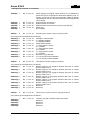
REVISIONS
Rev.#
Rev.Date
00
21/07/95
Revised pages
Second release
CMAPLC95070E
------- ---------------- --------------------------------------------------------------------------------------------------------------------01
25/08/99
Third release
CMAPLC99081E
The features described in this updating manual are fully implemented on the
S3000 Series systems with software versions after July 1999; the software
versions include in part the features described.
------- ---------------- ---------------------------------------------------------------------------------------------------------------------
Note:
Note: Pages marked by an asterisk (*) were removed, pages marked by a (+) symbol were
added, and pages without markings were modified.
Machine Logic Development (PLC) (01)
1
Series S3000
General
REVISIONS (cont.)
Rev.# Rev. Date
Note:
2
Revised pages
Note: Pages marked by an asterisk (*) were removed, pages marked by a (+) symbol were
added, and pages without markings were modified.
Machine Logic Development (PLC) (00)
Series S3000
General
INTRODUCTION
INTRODUCTION
This manual is intended for the (OEM) of machine tools and machining centers who wish to install the
SELCA series S3000 numerical controller.
This manual provides all of the information on the MACHINE LOGIC operated by the PLC integral to
the Series S3000.
The manual provides a description of the instructions used in programming the PLC, as well as
describing the system interface and the interchangeable commands. Also provided are complete
examples of real applications, form which ideas may be taken for writing custom applications.
When required, the manual calls out the differences between the Series S3000 system and the
preceding system (S1200). This information may be helpful for those who have been working with the
earlier system.
REFERENCES
In addition to this manual please refer to the following documents for further information on the S3000
system hardware and NC programming.
•
•
•
User's Manual (for Programming)
System Configuration Manual
Installation Manual
Machine Logic Development (PLC) (01)
3
Series S3000
General
SUMMARY
The manual is divided into three independent parts:
Part I
Programming language and operating procedures
This part contains descriptions of all the programming instructions, including simple
examples, as well as utilization procedures and the softkeys that control the operations in this
area.
Part II System Interface
This part describes all of the instructions exchanged by the PLC and the NC, including their
function and use.
Part III Programming examples
This part contains a few examples of actual applications which were made using the PLC
language.The contents of the individual chapters found in each of the parts is as follows:
Part I
Chapter 1 Characteristics and Usefulness
This chapter lists all of the primary characteristics of the SELCA Series S3000 and their
usefulness.
Chapter 2 Operating procedures
This chapter describes the softkeys used in the APPLICATIONS environment to execute such
programming operations as; editing, compiling, activating, and debugging.
Chapter 3 Program organization
This chapter describes the program structure as well as the format for constants and
variables used within the program.
Chapter 4 Pre-settings
This chapter contains a list of variables which must be set prior to beginning
programming. For example; inputs/outputs, impulse types, counters, logic definable
softkeys, internal variables and timers.
Chapter 5 Functions and Operations
This chapter describes the instructions used during the programming, including related
parameters and limits. The functions are subdivided into: logic, format variables conversion,
arithmetical/mathematical and string operations.
Chapter 6 Instructions for program controls
This chapter describes the functions which vary the program flux while it is running; such as,
jumps, loops, and subroutines.
Chapter 7 Special Functions
In the final chapter of Part I certain user functions are described such as; statistical
calculations, signal selection, and user messages.
4
Machine Logic Development (PLC) (00)
Series S3000
General
Part II
Chapter 1
This chapter contains descriptions of the registers, PLC/NC interface variables, including each
variable's characteristics and format. The registers are grouped by type or function.
Chapter 2
This chapter describes the functions of the registers described in the previous chapter, that is it
describes the control of the mandrels, axis movements, and tool changer control.
Chapter 3
This chapter briefly describes the modifications needed to convert a series S1200
program to an S3000 program.
Chapter 4
This chapter contains a table which summarizes the registers and associated variables
described in chapters 1 & 2. This table is particularly useful as a reference sheet for
programming.
Part III
The third part contains a single chapter which lists various program examples which may be
used on their own, or as starting points for writing programs to perform analogous work.
TERMINOLOGY AND SYMBOLS
All of the instructions and variables defined previously are capitalized and written in boldface (ex.
VARIAB), while those written in boldface and lowercase are references for generic instructions or
expressions which are to be assigned by the program (ex. operator).
In the instruction syntax all that is contained within these symbols [and], is optional and may even be
omitted.
The symbol | is used to separate choices in parameters; (for example A|B|C means either A, or B, or C
may be inserted.)
The keys of the keyboard are represented as they appear on the NC keyboard (except for the
alphanumeric keys). (es.
Note:
,
,
,
, ecc.).
The Return key is positioned vertically on the keypad (
in this manual for better use of space
). However it is represented horizontally
.
The term "set" indicates the forcing of a variable to the logic level "1" or "true".
The term "reset" indicates the forcing of a variable to the logic level "0" or "false".
S1200
T This symbol indicates the description of differences between the series S12000 and
S3000 systems. This will be particularly useful for those who have already installed or
have been using the S1200 system.
Machine Logic Development (PLC) (01)
5
Series S3000
General
INDEX
Part I
1. USES AND FUNCTIONS
1.1. MAIN CHARACTERISTICS OF THE SERIES S3000 ................................................................. 1-1
2. PROCEDURE
2.1. EDITING THE LOGIC .................................................................................................................. 2-2
Edit menu .......................................................................................................................... 2-3
Edit logic menu.................................................................................................................. 2-4
Advanced function menu................................................................................................... 2-5
Edit parameters menu....................................................................................................... 2-6
2.2. COMPILE LOGIC......................................................................................................................... 2-7
2.3. LOAD AND RUN.......................................................................................................................... 2-7
2.4. TRANSLATION OF PROGRAMS EDITED ON S1200................................................................ 2-8
2.5. LOGIC DEBUG ............................................................................................................................ 2-8
2.5.1. DYNAMIC DISPLAY .......................................................................................................... 2-8
2.5.2. GRAPHIC ANALYZER....................................................................................................... 2-10
Setting-up the graphic analyser ........................................................................................ 2-10
Trace analysis ................................................................................................................... 2-12
2.5.3. DISPLAY AND ANALYZER TABLES ................................................................................ 2-14
2.5.4. FORCED ASSIGNMENTS................................................................................................. 2-14
2.5.5. FORCED VALUES TABLES.............................................................................................. 2-15
2.5.6. RESET STATIC RAM ........................................................................................................ 2-15
2.5.7. CROSS REFERENCE GENERATION OF USED VARAIABLES .............................. 2-15
2.6. PLC TABLES MODIFICATIONS AND DIPLAYS ........................................................................ 2-16
2.7. FAST KEYS ................................................................................................................................. 2-16
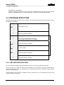
3. PROGRAM ORGANIZATION
3.1. GENERAL RULES....................................................................................................................... 3-1
3.2. PROGRAM STRUCTURE ........................................................................................................... 3-2
3.2.1. DECLARATION SECTION ................................................................................................ 3-2
3.2.2. INITIALIZATION SECTION................................................................................................ 3-3
3.2.3. PROGRAM SECTION ....................................................................................................... 3-3
Superfast logic .................................................................................................................. 3-3
Fast logic........................................................................................................................... 3-3
Slow logic .......................................................................................................................... 3-3
Superslow logic ................................................................................................................. 3-4
Synchronization................................................................................................................. 3-4
3.2.4. ROUTINES SECTION ....................................................................................................... 3-4
3.3. VARIABLES AND NUMBER FORMAT ....................................................................................... 3-4
3.3.1. VECTOR AND SINGLE VARIABLES ................................................................................ 3-5
3.3.2. STATIC AND DYNAMIC VARIABLES ............................................................................... 3-6
3.3.3. CONSTANTS..................................................................................................................... 3-6
3.3.4. CONFIGURABLE CONSTANTS FOR MACHINE LOGIC ................................................. 3-6
3.3.5. DISPOSITION OF SINGLE BITS INTERNAL TO THE VARIABLES................................ 3-7
3.3.6. ACCESS TO VARIABLE BITS .......................................................................................... 3-8
Single variables................................................................................................................. 3-8
Vectorial variables............................................................................................................. 3-8
3.3.7. ACCESS TO BITS OF ADJACENT VARIABLES ............................................................. 3-9
6
Machine Logic Development (PLC) (00)
Series S3000
General
4. INITIAL DECLARATIONS
4.1. DECLARATION OF PHYSICAL INPUTS / OUTPUTS ................................................................4-2
4.1.1. PHYSICAL INPUT/OUTPUT DECLARATION: REMOTE I/O MODULES..........................4-4
4.2. DECLARATION OF INTERNAL VARIABLES .............................................................................4-5
4.3. DECLARATION OF STRING .......................................................................................................4-6
4.4. DECLARATIONS OF EQUIVALENCES ......................................................................................4-7
4.5. PULSE..........................................................................................................................................4-8
4.6. TIMERS ........................................................................................................................................4-9
4.7. COUNTERS .................................................................................................................................4-11
4.8. LOGIC DEFINABLE SOFTKEY ..................................................................................................4-13
4.9. SOFTKEY AND MESSAGES WITH MULTILINGUAL TEXT .............................................. 4-14
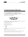
5. FUNCTION AND OPERATION
5.1. PROGRAMMING WITH ELEMENTARY LOGIC .........................................................................5-1
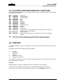
5.2. ARITHMETIC OPERATIONS.......................................................................................................5-2
5.3. FLOATING POINT MATHEMATICAL FUNCTIONS....................................................................5-3
5.4. COMPARE ...................................................................................................................................5-3
5.5. ROTATION ...................................................................................................................................5-4
5.6. FORMATS CONVERSIONS ........................................................................................................5-4
ENC - Search bit ...............................................................................................................5-4
DEC - Set bit .....................................................................................................................5-5
HI - Extracts the high byte from a word .............................................................................5-5
LO - Extracts the low byte from a word .............................................................................5-5
EXT - Conversion of a byte into a word.............................................................................5-5
BCD - Converts a binary number to BCD..........................................................................5-5
BIN - Converts a BCD number to byte or word .................................................................5-5
IFP - Converts a byte or word into floating point format ....................................................5-6
FPI - Converts floating point format into byte or word .......................................................5-6
5.6.1. COMPLEX EXPRESSIONS ...............................................................................................5-6
5.7. STRING OPERATIONS ...............................................................................................................5-7
5.7.1. NUMERICAL FUNCTIONS WITH STRING ARGUMENTS ...............................................5-7
VAL - Transforms an ASCII format to anuerical value ......................................................5-7
INSTR - Search for a string within a string ........................................................................5-7
LEN - String length ............................................................................................................5-8
STRCMP - String comparisons .........................................................................................5-9
5.7.2. STRING FUNCTIONS ON NUMERICAL ARGUMENTS ...................................................5-10
MKN$ - Converts a number into string format ...................................................................5-10
CHR$ - Generates an ASCII character .............................................................................5-10
STRNG$ - Generates a string of equivalent characters ....................................................5-11
5.7.3. STRING FUNCTIONS WITH STRING ARGUMENTS .......................................................5-11
MID$ - Extracts a small string from a larger string ............................................................5-11
LEFT$ - Extracts a string starting from the left..................................................................5-12
RIGHT$ - Extracts a string starting from the right .............................................................5-13
5.7.4. COMBINING STRINGS......................................................................................................5-13
6. INSTRUCTIONS FOR PROGRAM FLOW CONTROL
6.1. UNCONDITIONAL JUMP.............................................................................................................6-1
6.2. CONDITIONAL JUMP..................................................................................................................6-2
6.3. CONDITIONAL EXECUTION.......................................................................................................6-2
6.4. CALCULATED GOTO..................................................................................................................6-2
6.5. QUESTIONED GO TO .................................................................................................................6-3
6.6. LOOP............................................................................................................................................6-4
6.7. SUBROUTINE ..............................................................................................................................6-5
Machine Logic Development (PLC) (01)
7
Series S3000
General
7. SPECIAL FUNCTIONS
7.1. FLIP FLOP ................................................................................................................................... 7-1
7.2. MULTIPLEXER ............................................................................................................................ 7-1
7.3. TABLE SEARCH ......................................................................................................................... 7-2
7.4. MESSAGES FOR THE OPERATOR ........................................................................................... 7-3
7.5. MACHINE LOGIC PROGRAM COMMANDS .............................................................................. 7-4
7.5.1. PROGRAM COMMANDS USED DURING AUTOMATIC PROGRAM EXECUTION ........ 7-5
7.5.2. PROGRAM COMMANDS RUN FROM THE MANUAL MODE .......................................... 7-5
7.5.3. MACHINE LOGIC PROGRAM COMMANDS IN SEMIAUTOMATIC MODE
RUN............................................................................................................................. 7-5
Machine logic program commands: unit of measure ........................................................ 7-6
Machine logic program commands:functions not permitted.............................................. 7-6
Machine logic program commands: running in asynchronous mode ................................ 7-7
Part II
INTRODUCTION ......................................................................................................... 1
1. SIGNAL FLOW AND DATA EXCHANGE
1.1. NC STATUS................................................................................................................................. 1-1
1.2. AUXILIARY SYNCHRONOUS AND PREPARATORY FUNCTIONS ......................................... 1-2
1.2.1. ACQUISITION OF PLC TO NC SYNCHRONOUS INFORMATION .................................. 1-3
1.2.2. SIGNALLING COM SUBPROGRAM TERMINATION ....................................................... 1-3
1.2.3. SUPPLEMENTARY PARAMETERS I, J, K, Q ................................................................. 1-3
1.2.4. EXECUTION OF AUXILIARY FUNCTIONS “ON THE FLY” .............................................. 1-4
Auxiliar functions: notes on sending the speed................................................................. 1-4
1.3. ASYNCHRONOUS START, STOP, ALARM AND ACKNOWLEDGE CONTROLS ................... 1-5
1.4. TOOL ORIGINS AND COMPENSATION .................................................................................... 1-7
1.4.1. MANUAL TOOL CHANGE ................................................................................................. 1-7
1.4.2. TYPE S1200 MANUAL TOOL CHANGE ........................................................................... 1-7
1.4.3. AUTOMATIC TOOL CHANGE........................................................................................... 1-7
1.5. COMMANDS REGULATING AXIS FEEDS ................................................................................. 1-8
1.5.1. ENABLING AND LOCKING AXES .................................................................................... 1-8
1.5.2. AXES ALWAYS ACTIVE OR WITH LOCKING (M10 - M11)............................................. 1-9
1.5.3. AXES RELEASE (M45 - M46) ........................................................................................... 1-10
1.5.4. TRANSDUCER DISABLING.............................................................................................. 1-10
1.5.5. MANUAL MOVEMENT IN JOG ......................................................................................... 1-10
1.5.6. MANUAL MOVEMENT WITH HANDWHEEL.................................................................... 1-11
1.5.7. HOMING THE AXES ......................................................................................................... 1-11
Reference cycle using home switches.............................................................................. 1-12
Homing using the electrical zero of the transducer (marker) ............................................ 1-15
Homing using optical scales ............................................................................................. 1-16
1.5.8. MOVEMENTS IN MANUAL DURING HOLD STATE......................................................... 1-17
1.5.9. MOVEMENT IN MANUAL AND REFERENCING DURING PROGRAM
EXECUTION...................................................................................................................... 1-17
1.5.10. INFORMATION REGARDING THE AXES ...................................................................... 1-17
1.5.11. DYNAMIC COMPENSATION OF AXIS POSITION ......................................................... 1-19
1.5.12. OFFSET FOR CONTROLLED AXES .............................................................................. 1-19
Additional origin offset for controlled axes ........................................................................ 1-19
1.6. MANAGEMENT OF CONTACT MEASUREMENT PROBE........................................................ 1-20
1.7. AXIS SOFTWARE LIMITS........................................................................................................... 1-20
Controller axis software limits: de-activating error E93 ..................................................... 1-21
1.7.1. ADDITIONAL SOFTWARE LIMITS ............................................................................ 1-21
8
Machine Logic Development (PLC) (00)
Series S3000
General
1.8. SPECIAL TYPE AXIS MANAGEMENT .......................................................................................1-22
1.8.1. PARALLEL (GANTRY) AXES ............................................................................................1-22
1.8.2. PROGRAMMABLE NON - CONTROLLED AXES .............................................................1-22
1.8.3. MASTER SLAVE AXES (NC "MS" OPTION).....................................................................1-23
1.8.4. READING INPUTS AND WRITING ANALOG OUTPUTS: REMOTE I/O
MODULES .........................................................................................................................1-23
1.9. READING AND WRITING ANALOG INPUTS AND OUTPUTS ..................................................1-25
1.10. EXCHANGE OF DATA BETWEEN PLC AND PART PROGRAM ............................................1-25
1.11. NC VIDEO DISPLAY WINDOWS..............................................................................................1-26
1.12. SYSTEM DATE AND TIME........................................................................................................1-27
1.13. SIGNALS FOR COPYING AND DIGITIZING SURFACES ........................................................1-27
1.13.1. STATUS REGISTER OF COPYING AND DIGITAL PROBE .................................. 1-29
1.14. VARIABLES TO VERIFY SYSTEM EXECUTION TIMES .........................................................1-30
1.15. ERROR SIGNALS ACCESSED BY THE LOGIC ......................................................................1-30
1.16. READING AND MODIFYING AXIS CONFIGURATION PARAMETERS...................................1-31
1.17. MANAGEMENT OF NUMEROUS SIMULTANEOUSLY INTERPOLATING AXIS
GROUPS (GDA). .......................................................................................................................1-32
1.18. MANAGEMENT OF DIGITAL DRIVES FOR AXIS AND SPINDLE...........................................1-33
2. DEDICATED INTERNAL MODULES
2.1. SPINDLE MANAGEMENT MODULE ..........................................................................................2-1
2.1.1. SIGNALS AND REGISTERS FOR SPINDLE ROTATION.................................................2-1
2.1.2. SIGNALS AND REGISTERS FOR RANGE SELECTION..................................................2-2
2.1.3. SIGNALS AND REGISTERS FOR SPINDLE ORIENTATION..........................................2-3
Absolute position orientation .............................................................................................2-3
Unidirectional orientation...................................................................................................2-3
2.1.4. SIGNALS AND REGISTERS FOR SPINDLE SYNCHRONIZED SPINDLE ......................2-3
2.1.5. SIGNALS AND REGISTERS COMMON TO ALL SPINDLE TYPES ................................2-4
2.1.6. SPINDLE WITH OR WITHOUT TRANSDUCER ...............................................................2-5
2.1.7. NOTE ON THE FIXED CYCLE G84 ................................................................................2-6
Related signals and registers ............................................................................................2-6
2.2. INDEPENDENT AXIS MOVEMENT MODULE ...........................................................................2-7
New variables....................................................................................................................2-9
2.3. TOOL CHANGER CONTROL MODULE ....................................................................................2-10
2.3.1. SIMPLE DEFINITIONS ......................................................................................................2-10
2.3.2. TYPES OF TOOL CHANGER CONFIGURATION.............................................................2-11
2.3.3. CONFIGURATION OF AUTOMATIC TOOL CHANGERS .................................................2-12
Tool dispositions................................................................................................................2-12
Tool storage geometry.......................................................................................................2-12
Types of tool storage management ...................................................................................2-12
2.3.4. SEQUENCE DEFINITIONS ...............................................................................................2-13
Asynchronous tool changes ..............................................................................................2-13
Synchronous tool changes ................................................................................................2-15
PLC program implementation............................................................................................2-17
Activation of tool changer module .....................................................................................2-17
Actuation of sequencer......................................................................................................2-17
Tool length correction........................................................................................................2-18
Decoding ‘T’ program and selecting the work sequence...................................................2-19
2.3.5. SEQUENCE INTERRUPTION ...........................................................................................2-19
Integrated tool life management ........................................................................................2-20
Description of the PLC variables .......................................................................................2-20
2.3.6. DIFFERENTIATING THE TOOL FAMILY ..........................................................................2-20
2.3.7. DIFFERENTIATING TOOLS WITH DIFFERENT SHAPES...............................................2-20
2.3.8. DESCRIPTION OF PLC VARIABLES................................................................................2-21
2.3.9. TOOL TABLES...................................................................................................................2-22
Writing to tool tables from the PLC ..................................................................................2-23
2.4.SERIAL LINE MANAGEMENT MODULE FROM PLC .................................................................2-24
Machine Logic Development (PLC) (01)
9
Series S3000
General
3. ADAPTING THE PLC PROGRAM FROM S1200 TO THE S3000
4. SUMMARY OF SIGNALS AND REGISTERS
4.1. SYMBOLS AND CONVENTIONS................................................................................................ 4-1
4.2. INTERCHANGEABLE AND FLOW OF SIGNALS ...................................................................... 4-3
NC status ........................................................................................................................ 4-3
Synchronous communication with the NC ...................................................................... 4-3
Synchronous auxiliary and preparatory functions ........................................................... 4-3
Asynchronous Start, Stop, Alarmsand Aknowledge controls.......................................... 4-4
Part origins and Tool length compensation..................................................................... 4-4
Enabling and disabling axes ........................................................................................... 4-4
Axes always active or with locking.................................................................................. 4-4
Axes to be disabled ........................................................................................................ 4-4
Disabling transducers ..................................................................................................... 4-5
Manual JOG.................................................................................................................... 4-5
Manual movement with handwheel................................................................................. 4-5
Homing the axes ............................................................................................................. 4-5
Manual movement and homing during program execution ............................................. 4-5
Axis information .............................................................................................................. 4-5
Axis status ...................................................................................................................... 4-6
Control of transducers and electronic handwheels......................................................... 4-6
Dynamic compensation of axis position.......................................................................... 4-6
Offset of controlled axes ................................................................................................. 4-6
Contact probe management ........................................................................................... 4-6
Axis software limits ......................................................................................................... 4-6
Parallel axes (Gantry) ..................................................................................................... 4-7
Programmable non-controlled axes ................................................................................ 4-7
Reading and writing analog inputs and outputs........................................................ 4-7
Data exchange between PLC and part program ...................................................... 4-7
NC video display window ................................................................................................ 4-7
System date and time ..................................................................................................... 4-8
Copying and digitizing of surfaces .................................................................................. 4-8
Variables to verify system execution times ..................................................................... 4-9
Error signals accessed by logic ...................................................................................... 4-10
Reading and modifying axis configuration parameters ................................................... 4-10
4.3. DEDICATED MODULES ............................................................................................................. 4-11
Spindle rotation ............................................................................................................... 4-11
Range change selection ................................................................................................. 4-11
Spindle orient .................................................................................................................. 4-11
Synchronization between spindles.................................................................................. 4-12
Common to all operations ............................................................................................... 4-12
Fixed cycle G84 .............................................................................................................. 4-12
Independent axis movement module .............................................................................. 4-12
Tool change management module ................................................................................. 4-14
Tool tables ...................................................................................................................... 4-15
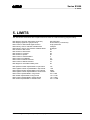
5. LIMITS
10
Machine Logic Development (PLC) (00)
Series S3000
General
Part III
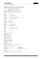
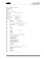
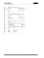
1. PLC PROGRAMMING EXAMPLES
BAS300F - Basic machine (3 axes and spindle) ...............................................................1-2
COMI3045 - 3 axis machine, slide clamps, spindle orient.................................................1-5
AXM11 - Selective axis clamping ......................................................................................1-10
AUXON - Auxilliary control logic.......................................................................................1-11
GEVOL3 - Single handwheel of X, Y, Z axes...................................................................1-12
SPIND1 - Spindle rotation .................................................................................................1-13
SPIND2 - Spindle orient ....................................................................................................1-15
SPIND3 - Range change...................................................................................................1-16
LUBMET - Lubrication based on axis travel ......................................................................1-17
LUBIN3 - Basic intermttent lubrication .............................................................................1-19
LUBMOV - Lubrication timed only when axes are moving ................................................1-20
ZERIAX - Automatichome axes cycle ...............................................................................1-21
ESRNDCU - Random tool change with load / unload in masked time ..............................1-23
SCROLLIN - Manage upto 128 messages with on screen scrolling .................................1-28
SHIFTZ - Example of compensation for Y fall as a function of Z ............................... 1-29
AXBLOC1 - Clamp axes with timed wait ...........................................................................1-30
AXBLOC2 - Clamp axes with external enable...................................................................1-31
ESSINCU - Synchronous tool change with grid ................................................................1-32
AXP2P - Control of tool storage axis from PLC.................................................................1-37
COMMUCM -Switch spindle with C axis ...........................................................................1-39
NEWFILT - Numerical filter ...............................................................................................1-41
TABUTE1 - Reorder tool position in table .........................................................................1-42
TESTAR - Indexed head moved by spindle motor ............................................................1-43
APPENDIX
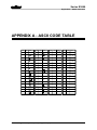
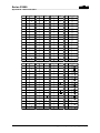
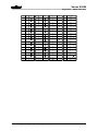
APPENDIX A – ASCII CODE TABLE ..........................................................................A-1
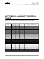
APPENDIX B - AUXILIARY FUNCTION TABLE .........................................................B-1
APPENDIX C - NEW SERIES S3000 FUNCTIONS COMPARED TO THE S1200
SYSTEM..........................................................................................C-1
C.1.1 SYSTEM MANAGEMENT ........................................................................................................C-1
C.1.2 PROGRAM DEBUGGING AND SYSTEM VERIFICATION ......................................................C-2
C.1.3 PLC PROGRAMMING...............................................................................................................C-3
APPENDIX D - DIAGNOSTIC MESSAGES.................................................................D-1
Machine Logic Development (PLC) (01)
11
Series S3000
General
12
Machine Logic Development (PLC) (00)
Series S3000
PART I
PROGRAMMING
LANGUAGE
AND
OPERATING PROCEDURE
Machine Logic development (PLC) - Part I (00)
Series S3000
Machine Logic Development (PLC) - Part I (00)
Series S3000
1. Uses and functions
1. USES AND FUNCTIONS
The Series S3000 offers a selection of controls to satisfy the growing use of machine tools and factory
automation in general.
The CNC S3045 is particularly useful for milling machines for tool makers and mold and die shops,
machining centers with multiple axes, accurate machining at high speeds and for complex surface
work.
The CNC S3040 supplies an integrated solution which is compact and cost effective for work cells, and
machining centers for production mill work and automated assembly stations for flexible high volume
production.
The CNC S3024 systems are designed for lathes, turning centers and a large number of multi-axis
work cells with slow cycles.
1.1. MAIN CHARACTERISTICS OF THE SERIES S3000
The following describes some of the characteristics and uses of the Series S3000 controls.
Considering the limited space and scope of this manual. Not all of the characteristics of each model
are described, only some of the more significant ones. For more detailed information please refer to
the technical Specifications for the particular model in question.
In the fully configured higher level systems the main features are as follows:
•
Advanced 2-D and 3-D conversational programming with interactive graphics and integrated
PROGET2 language.
•
Control of up to 16 axes, including 4 spindles.
•
Control of 8 axes simultaneously.
•
Utilizes all types of transducers (rotary and linear incremental encoders, fiber optics, absolute and
cyclical resolvers).
•
Up to 8 independent PLC programs for controlling groups of auxiliary axes.
•
Standard execution speed over 300 blocks per second, increased to 1000 blocks per second in the
P (Plus) version.
•
Integral PLC with high level language including a graphic and numeric analyzer.
Machine Logic Development (PLC) (00)
1-1
Series S3000
1. Uses and functions
•
Digital I/O: 32 inputs and 24 outputs, expandable to 384 inputs and 288 outputs.
•
Analog I/O: 24 outputs and 41 inputs, plus 8 inputs for temperature probes.
•
Tool Center Point Management function TCPM, for 5 axis machines with automatic control of tool
to work piece contact in three dimensions, with bi-rotational heads and rotating or tilting tables.
(Version P)
•
Cubic interpolation for high speed work of complex shapes (Version P)
•
Three dimensional surface scanning for digitizing and direct copying
•
Mass storage (DOS compatible hard disk, and floppy disk)
•
Interface and communication software for serial and network communication (point to point and
multi-point).
•
Expandable configuration (L and PL) allowing additional I/O and transducer and hard disk
interfaces as well as network connections.
•
Compatibility with earlier SELCA CNC models.
1-2
Machine Logic Development (PLC) (00)
Series S3000
2. Operating procedure
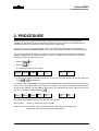
2. PROCEDURE
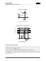
Before examining the program structure and writing instructions, it is helpful to understand the
operating procedures for the PLC machine logic programs. The procedures for the peripherals not
described herein may be found in the User's Manual for Programming.
Programs can only be run and debugged if +24V is present on the I/OMIX PC board and all of its
expansion cards (see Installation Manual). This is not a requirement for editing or compiling programs.
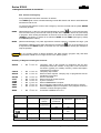
The PLC programming environment, as well as the machine parameter configuration environment
(APPLICATION) are not normally accessible to the user. To obtain access to this environment it is
necessary to follow the procedure below:
1. Press the
key
2. Press the
key
The following softkey menu appears.
NC
OPERATIONS
LOGIC
MESSAGES
PART
PROGRAMS
PERIPHER
MONITOR
SETUP
UTILITIES
TOOLS
DIAGN
TOOLS
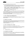
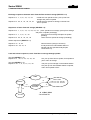
3. To access the APPLICATIONS environment for the first time after turning ON the NC, press the
keys
+
simultaneously.
The softkey LOGIC MESSAGES changes to LOGIC SYS/SETUP and remains that way until the NC is
turned OFF. The softkey menu then appears as follows. The LOGIC SYS/SETUP softkey allows
access to the machine logic described in this manual. For subsequent access it suffices to press the
(F2) key or LOGIC SYS/SETUP softkey
NC
OPERATION
LOGIC
SYS/SETUP
PART
PROGRAMS
PERIPHER
.
MONITOR
SETUP
UTILITIES
TOOLS
DIAGN
TOOLS
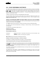
The are two modes of operation for PLC program maintenance:
EDIT LOGIC
- to write or modify an existing program
DEBUG LOGIC - to verify the the PLC program function, the integrity of the inputs and
outputs and the correct functioning of the algorithms.
Machine Logic Development (PLC) - Part I (01)
2-1
Series S3000
2. Operating procedure
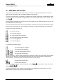
2.1. EDITING THE LOGIC
The procedures selected from this menu allow the writing of PLC programs directly on the machine
using all of the instructions and commands explained in this manual.
To write a new program it is necessary to respond to the system prompt with an alphanumeric name
with a maximum of 8 characters in capitol letters. The first character must not be a number. Then
press
.
If the program has already been stored in memory it will appear on the display otherwise a new one will
be created under the name given.
The menu functions allow the insertion and modification of text the movement and cancellation of large
blocks of text, copying text from other programs, substitution of words and automatic line numbering.
The keys for moving the cursor are:
to move up one line
to move down one line
to move to first line in the program
to move to the last line in the program
to move one page down
to move one page up
To move the cursor along a line:
to move to right of a character
to move to left of a character
+
to move to the beginning of a line
+
to move to the end of a line
All of the operator or machine dialog operations are effected by softkey and if necessary an associated
request line for parameters. These are organized within menus and are accessed by activating the
relevant softkey. The following keys are reserved to speed-up this process:
returns to the previous menu
returns to the main menu
The written program is saved automatically each time the
exited by
or
key is pressed or when the editor is
.
The functions used for writing, editing, and modifying PLC programs are reviewed below. For more
details please consult the User and Programmers Manual.
2-2
Machine Logic Development (PLC) - Part I (01)
Series S3000
2. Operating procedure
Edit Menu
To access the edit menu perform the following steps:
1. From the APPLICATIONS environment menu shown previously press the softkey LOGIC
SYS/SETUP to access the main applications menu shown below:
LOGIC
EDIT
LOGIC
DEBUG
SYSTEM
SETUP
SYS SETUP
FILES
SCREEN
CONFIG
FEEDBACK
ERR COMP
COM PROG
EDIT
PERIPHER
FLASH
MEMORY
BACKUP /
RESTORE
The softkey present in this menu, with the exception of the first two, are described in the System
Configuration Manual, which should be used for reference.
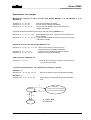
2. Press the LOGIC EDIT. Softkey to access the following menu:
MEMORY
FLOPPY
DRIVE
FLASH
MEMORY
EDIT
PLC LOGIC
COMPILE
PLC LOGIC
COMPRESS
COMP OUT
LOAD AND
RUN PLC
RENAME
PROGRAM
COPY
PROGRAM
DELETE
PROGRAM
The first three function keys (
,
,
) and the last three (
,
and
) control the same
functions as the equivalent softkeys in the NC programming environment. For details refer to the User
and Programmer's Manual.
Other softkeys function as follows:
LOGIC EDIT
Activates the logic editing environment from which it is possible to
write and maintain a PLC program.
COMPILE LOGIC
Compiles into executable instructions those programs created or
modified using logic edit.
COMPRESS
COMP OUT
Running the LOGIC COMPILER with this function enabled (default)
will obtain a shorter executable file than if it were compiled
uncompressed. In the compressed mode the compiling function takes
longer.
Note: Compiling compressed programs requires more active memory space
than normal compiling, therefore memory shortage problems may arise
when particularly long programs are compiled on systems with limited
memory.
Machine Logic Development (PLC) - Part I (01)
2-3
Series S3000
2. Operating procedure
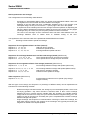
Edit Logic Menu
When the EDIT LOGIC softkey is pressed a list of all the present logic programs is displayed in the
center of the screen. One of these may be selected by moving the cursor over the desired program
useing the
or
. arrow keys. The name of the chosen program will also appear in the command
line. If a new program is desired, it is necessary to write the program name over the one present in the
command line.
After selecting or writing in a name, press the softkey EDIT LOGIC (
) or
. A new menu will
appear along with a listing of the program if already existing. A new program may be written directly
using the keyboard. To modify or delete program blocks while editing, the following softkeys should be
used:
INSERT
BLOCK
MODIFY
BLOCK
DELETE
BLOCK
STRING
SEARCH
ADVANCED
EDITING
The function of each softkey for PLC programming is as follows:
INSERT BLOCK
To insert a new program line, position the cursor on the block which comes
directly after the one which needs inserted (the INSERT BLOCK function is
active as soon as you enter this menu); write the new block then press
.
MODIFY BLOCK
Press this key to modify the line the cursor is currently positioned on. Modify
the block as it is presented within the command line box, then press
DELETE BLOCK
.
Press this key to delete the line on which the cursor is currently
positioned. A confirmation message is delivered:
Do you want to delete? (YES/NO)? Yes
Press
STRING SEARCH
.
This key starts the search for a string of characters within the program
starting from the cursor position. If a number is specified the cursor is moved
directly to that line in the program. Both the character string and line number
must be followed by a
.
ADVANCED FUNCTIONS This key activates a menu for block operations such as text copy and editing
parameters. To use all of the softkeys from this menu sufficient memory area
is needed. In the cases where available memory is limited the available
functions are limited to two.
2-4
Machine Logic Development (PLC) - Part I (01)
Series S3000
2. Operating procedure
Advanced function menu
When the ADVANCED FUNCTION softkey is selected and sufficient memory space is available, the
following menu will appear:
HIGHLIGHT
BLOCK
DELETE
BLOCK
COPY
BLOCK
MOVE
BLOCK
DELETE
FROM HERE
REPLACE
STRING
IMPORT
RENUMBER
FROM OTHER BLOCKS
EDITING
PARAMS
CANCEL
MODIF
In the case where there is insufficient memory only the following two softkeys appear:
DELETE
FROM HERE
REPLACE
STRING
HIGHLIGHT BLOCKS This key is used to highlight a block or group of blocks to be worked on. To
highlight the blocks move the cursor to the first block to be selected use
or
) keys press the softkey HIGHLIGHT BLOCK, position the cursor on
the last block to be selected and press the same key.
DELETE BLOCKS
Will delete the highlighted blocks confirm with
COPY BLOCKS
Copy blocks previously highlighted to another area in the program.
Move to the desired position for the block using the
.
or
keys,
press
to confirm. The block will be inserted on line just below
the cursor position.
MOVE BLOCKS
Move blocks previously highlighted to another area in the program.
Move to the desired position for the block using the
or
keys,
then press
. The block will be inserted on line just below the
cursor position.
DELETE FROM HERE Deletes all lines to the end of the program, starting with the line on which the
cursor is presently positioned on. The following message appears:
Delete all sucessive blocks? (YES/NO)? YES
Press
CHANGE STRING
to confirm.
Substitutes one string of characters for another by searching for the desired
string starting from the cursor position. The following message will appear:
Replace (string 1/string 2):
Write in the new string to be substituted, and confirm with
Machine Logic Development (PLC) - Part I (01)
.
2-5
Series S3000
2. Operating procedure
COPY FROM OTHER
Insert a block copied from another program into the present program
proceed as follows:
• Press the IMPORT FROM OTHER softkey for a list of programs in
memory.
• Select the program which contains the block to be extracted and press
•
Highlight the block to be copied then press
program which is to receive the block.
•
Position the cursor at the point where the block is to be inserted and press
the softkey COPY BLOCK.
twice to return to the
RENUMBER BLOCKS
Renumbers the program lines according to the edit parameters (increment,
number of spaces...). Automatic line numbering occurs only if lnew lines are
added to the end of the program.
EDIT PARAMETERS
Changes the line numbering parameters. Activates a new softkey menu from
which the parameters may be adjusted.
DELETE MODIFIC.
Deletes the last changes made using the advanced function keys (this can
only be accomplished from the ADVANCED FUNCTIONS menu).
Edit parameters menu
When the EDITING PARAMS softkey is pressed the following menu appears:
BLOCK #
FORMAT
BLOCK
START #
CHANGE SPACES
BLOCK #
INCREMENT
RENUMBER
BLOCKS
TRANSLATE
FROM 1200
This softkey controls the spacing before each block for the sequence
number. The valid numbers are between 3 and 8. Press
completed.
CHANGE FIRST
This softkey sets the first sequence number, or first block. Valid numbers are
between 1 and 10. Press
CHANGE STEP
when
when completed.
This key adjusts the spacing between individual blocks and between blocks
and their sequence number. Valid numbers are between 1 and 10. Press
to confirm.
2-6
Machine Logic Development (PLC) - Part I (01)
Series S3000
2. Operating procedure
RENUMBER BLOCKS
To apply the new parameters press this key followed by
return to the previous menu.
. You will then
TRANSLATE PLC 1200 The system S1200 programs differ slightly from the Series S3000 to make
them completely compatible press this softkey while editing the older
programs.
2.2. COMPILE LOGIC
This is the first operation to be performed after creating a new program or modifying an old one to
verify correct syntax, and to render it executable by the computer. During the execution of this
command the system displays the line number being compiled any errors will stop the program. An
error message will be displayed together with the program line number in which the error was found. If
the compiling operation is successful the following message will appear:
Program compile end: “program name”.
If an error is found during compiling, the software will automatically return to the edit mode and place
the cursor at the line where the error was found.
2.3. LOAD AND RUN
The LOAD AND RUN softkey accessible from the EDIT LOGIC menu, resets the PLC variables
memory and starts the execution of the last PLC program to be compiled. The key is illuminated when
a PLC program is being executed.
It is possible to halt the program by pressing the same key.
The PLC may be de-activated automatically in the following cases:
•
Hardware errors such as losing 24V on the main board, or high current draw on the outputs, etc..
•
Grave software errors such as CALL and RTS out of sequence long fast and superfast calculations
and floating point errors (overflow, underflow, etc.). In these cases an error message appears
which describes the type of fault which halted the program.
•
Changes in the base configuration of the machining center such as number of axes, etc.
The DEBUG LOGIC menu contains the softkey ENABLE LOGIC which performs the same function as
LOAD AND RUN except it does not reset the memory.
Machine Logic Development (PLC) - Part I (01)
2-7
Series S3000
2. Operating procedure
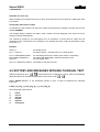
2.4. TRANSLATION OF PROGRAMS EDITED ON S1200
The series S3000 systems adopt the following PLC program line numbering syntax:
Nxx
instruction
in the earlier Selca systems the syntax was:
xx
instruction
To automatically convert the old numbering system to the new it is necessary to:
•
edit the program to be converted
• Press the following softkeys in order: AVANCED FUNCTIONS, EDIT PARAMETERS,
TRANSLATE PLC 1200.
This will overwrite the old program.
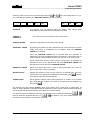
2.5. LOGIC DEBUG
The debug environment is reached by pressing the LOGIC DEBUG softkey from the main applications
menu. The following menu will appear:
ENABLE
PLC LOGIC
DYNAMIC
DISPLAY
GRAPHIC
ANALYZER
PLC LOGIC
MESSAGES
CROSS
REFERENCE
SCREEN
TABLES
ANALYZER
FILES
FORCING
FILES
RESET
SRAM
In this environment all system diagnostic signals and variables may be displayed and run. These tools
are not just used during the set-up of the machine, but may be used over the entire life of the machine.
It is also possible when for debugging to store in tables all display variable settings, so that the system
may be checked out in cases of malfunctions or service and repairs.
The functions available in this environment are described in the following sections.
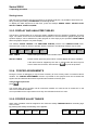
2.5.1. DYNAMIC DISPLAY
This function displays the current numerical value of signals or variables.
The softkey menu is as follows:
ENABLE
DISPLAY
2-8
INSERT
NAME/EXPR
MODIFY
NAME/EXPR
DELETE
NAME/EXPR
DISPLAY
INPUT
DISPLAY
OUTPUT
FORCED
ASSIGN.
..MORE..
Machine Logic Development (PLC) - Part I (01)
Series S3000
2. Operating procedure
The function of each of the softkeys is as follows:
ENABLE DISPLAY
Allows the freezing of variables which are changing rapidly so that they may
be more easily read. These values remain on the display until the key is
pressed again (however the variable continues to beupdated within the
system). The key is active when this menu is entered; if it becomes
deactivated it signifies that the variables are frozen.
INSERT NAME/EXP.
The variable name to be displayed must be typed after this softkey is
pressed; press
to confirm.
To insert more names on the same line place the ";" symbol between each
name.
MODIFY NAME/EXP.
DELETE NAME/EXP.
After selecting a variable using the
or
modify the selected variable. Press
to confirm.
, keys press this softkey to
Deletes the variable on which the cursor is positioned.
DISPLAY INPUT
DISPLAY OUTPUT
This key allows the verification of the binary status of the input and
output bytes on the I/O MIX card. The display will present a variable
IN_001(n); where (n) is a binary number. The 8 bits represent the states
of the 8 relative input/output bytes starting from right to left.
In screen, the
and
keysare used to view the similar signals from
the other I/OMIX cards and are identified by the variables IN_00x(n).
FORCED ASSIGNMENT This function may be used to force a value on a variable and measure its
effect immediately (see a description of forced values further ahead).
ADVANCED FUNCTIONS Activates a new menu with more commands.
By pressing the ..MORE.. softkey the following menu appears:
DECIMAL
BINARY
SEARCH
ASSIGN.
EXPAND
EQUATION
CLEAR
ALL
SAVE
TABLE
DECIMAL/BINARY
Changes the display format from decimal to binary and vice versa for the
variable selected by the cursor.
SEARCH ASSIGN.
By supplying the name of a variable used in the active PLC program, all of its
assigned values are searched. Related equations are displayed dynamically.
Machine Logic Development (PLC) - Part I (01)
2-9
Series S3000
2. Operating procedure
EXPAND EQUATION
Permits equations to be expanded so that all of the terms in the equation
selected by the cursor are displayed separately. Usually this function is used
after the SEARCH ASSIGN. softkey is pressed.
CLEAR ALL
Erases all of the names and expressions present in the dynamic display.
SAVE TABLE
Stores all of the names and expressions displayed so that they may be
recalled later by RECALL TABLE. It is necessary to supply the name of the
table to be stored, then press
.
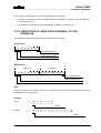
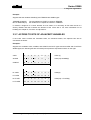
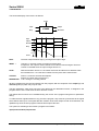
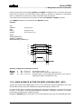
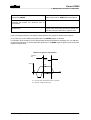
2.5.2. GRAPHIC ANALYZER
The system is designed to display a graphic signal of movement with respect to time of 16 signals in bit
format(such as; inputs, outputs, internal variables) and 4 numerical variables (in non-bit format). The
signals and numeric variables are displayed simultaneously using different colors to distinguish them
even when they may be overlapping. The trace is formed by conditioning the stored signal by use of a
trigger function.
If a variable is to be traced in a pre-established field not in bit format it will be necessary to specify it
using the following syntax:
nomevar[,min, max]
If the limits are not specified an "autoscaling" mechanism will allow the display of the variable in the
center of the screen. This mechanism may not be satisfactory when the signal is changing at high
frequency ( for example, electrical noise on a small signal).
To insert more names at the same time insert the character ";" between each name.
Setting-up the graphic analyzer
To set the graphic analyzer parameters the softkey GRAFIC ANALYZER is pressed from the DEBUG
menu:
ACQUIRE
ENTER
NAME/EXPR.
MODIFY
NAME/EXPR.
DELETE
NAME/EXPR.
TIME
BASE
ACQUIRE
TIME
FORCE
ASSIGN.
TRIGGER
NAME/EXPR
TRIGGER
TIMING
..MORE..
The function of each key is as follows:
ENTER NAME/EXPR.
After pressing this key the variable name to be displayed is typed and then
the
key is pressed to confirm.
MODIFY NAME/EXPR. After having selected a variable this softkey will allow for the name to be
changed to that of another variable, as well as for allowing the max/min limits
to be changed. When finished press
.
DELETE NAME/EXP. Removes the variable on which the cursor is resting form the display.
2-10
Machine Logic Development (PLC) - Part I (01)
Series S3000
2. Operating procedure
TIME BASES
Selects the interval between two consecutive scans of the signals being
analized. Normally it is a multiple of 10 mSec (PLC scanning time).The
default value is 10 mSec.
To analyze quickly changing phenomena such as axes responses or traces
of variables used in the superfast logic section, a time base may be used
which is equal to the axis standard defined during configuration.
It must be noted that it is not possible to analyze signals using a time base
which is smaller than their update times. For example signals from the high
speed logic section (which have a scanning rate of 10 mSec), the time base
used should be 10 mSec.
A 2 mSec time base may be used to analyze the dynamics of the machine
axes, thereby displaying instantaneous speed, path error, or other analog
outputs.
ACQUIRE TIME
This is the time period specified for analyzing the signal in question. The
number of PAGES is calculated based upon this number and the time base,
which is then rounded to the highest multiple of 2. Each page contains 512
points separated by a distance equal to the time base. The maximum
number of pages is 8.
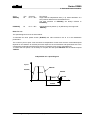
Example: ACQTIM=30 Sec; TIMBAS=10 mSec
(30/.01)=3000 values must be acquired; these are divided into
(3000/512)=5.86 pages, which is rounded up to the highest multiple of 2, that
being 8.
FORCED VALUE
Permits the value of a variable to be forced and to immediately gauge its
effect. (see description further ahead)
NAME/EXP TRIGGER
Permits the insertion of an equation (written within parenthesis using a valid
PLC syntax), or a signal which, when it assumes the value zero, activates the
storage of the analyzed signal according to the position of the trigger
selected.
TRIGGER TIMING
This key establishes the trigger position with respect to the signal acquisition
time. In other words, the display time may be posted before, after, or in time
with the trigger.
Pressing this key will cycle the trigger position between three distinct
selections:
-
ACQUIRE
PRE:
MID:
END:
trace before trigger
trace in time with trigger
trace after trigger.
After having chosen the above display settings, the analyzer must be
activated. Only then the acquisition is activated and three trigger equation
checked.
When the trigger equation is satisfied the percentage of actual acquisition
time will be displayed until 100% is achieved, at which time the ANALYZE
TRACE menu appears.
Machine Logic Development (PLC) - Part I (01)
2-11
Series S3000
2. Operating procedure
If the ACQUIRE key is pressed without having set the trigger parameters, the
analyzer continuously scans the display signals until the key is pressed
again. This application may be useful for example when calibrating
movement or position.
..MORE..
Activates a new menu with other functions.
The ..MORE.. softkey calls up the following menu containing functions as described ahead:
.
FIND
ASSIGN
EXPAND
EQUATION
DELETE
ALL
SAVE
VAR LIST
FIND ASSIGN.
By supplying a variable name used in the active PLC program this function
searches all assignments of that variable, the relative equations are then
displayed between the expressions to be traced.
EXPAND EQU.
Permits the expansion, or separate tracing of each of the terms contained
within the equation highlighted by the cursor. This function is usually used
after an assignment search (SEARCH ASSIGNMENT).
DELETE ALL
Deletes all names and expressions of the present traces.
STORE VAR LIST
Stores graphic analyzer names and expressions in a table, to be recalled
later using RECALL LIST The name of the table must be entered, then press
.
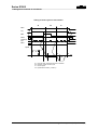
Trace analysis
Activating the trace analyzer ANALYZE TRACE allows the quantification of signal acquisition times
and values, it also allows the changing of the display scale and the number of pages with which the
traces are displayed.
It is always possible to observe on the display:
- The time base for acquisition of the traces (preceded by the symbol BT:)
- The acquisition duration time(preceded by the symbol FR:)
- Horizontal cursor time intervals (CURSOR + and CURSOR#)
- The reduction factor for that which is being analyzed (preceded by the symbol X)
- The percentage of time between the trigger arrival and the total acquisition duration
- The trigger position (preceded by the symbol TP).
There are two cursors available called + and #, which once activated by their relative softkeys
CURSOR+ and CURSOR#, may be moved using the horizontal .
changes in time.
and
arrow keys to measure
The
and
arrow keys move two other cursors also called + and #. These are activated
simultaneously with the horizontal cursors and permit the selection of variables whose numerical value
is questioned by positioning the cursor on the trace. These values are displayed on the lower portion
of the screen in the same color as the trace they represent.
2-12
Machine Logic Development (PLC) - Part I (01)
Series S3000
2. Operating procedure
Zooming in and out on a trace is performed by using the
and
keys, the scaling factor is 1,2,4,
or 8. The softkeys present in the ANALYZE TRACE menu are as follows:
ACQUIRE
CURSOR +
CURSOR #
ACQUIRE
CURSOR +
CURSOR #
CURSOR
SPEED
HIGHLIGHT
TRACE
REDISPLAY
TRACE
ADJUST
SCALE
SAVE
TABLE
The analyzer may be activated using this softkey, after having made
modifications to the parameters controlled by this menu.
Turns ON or OFF the horizontal and vertical cursors.
CURSOR SPEED
Permits the adjustment of horizontal cursor speed.
HIGHLIGHT TRACE
By pressing this softkey the trace selected by the cursor becomes a reverse
image. The traces so highlighted are not redrawn when the REDRAW
TRACE key is pressed.
When the REDRAW TRACE key is pressed after this operation is
performed, only the non-highlighted traces are retraced. This function may be
used to analyze a large number of traces one at a time, or in small groups.
traces selected are stored in memory and to recall them it is necessary to
position the cursor on the signal name and press HIGHLIGHT TRACE until
the selection is made, then press REDRAW TRACE.
REDISPLAY TRACE
Moves and redraws the traces in such a manner to position the cursor as
close to the screen center as possible.
ADJUST SCALE
Permits the change of max and min limits for a selected trace using the
vertical cursor; by making the modifications and pressing the
trace with its new limits will be displayed.
STORE TABLE
key the
Stores graphic analyzer names and expressions in a table, to be recalled
later using RECALL TABLE. The name of the table must be supplied and
then press
.
The analyzer may also capture glitches, which may happen when a time base of greater than 10
mSec is used to analyze a signal and all that is displayed is a point, which indicates that the signal was
moving slower than the base selected, and capture in 10 mSec interval.
If a graphics printer is available a hard copy of the display may be made by pressing the
keys (to obtain the analyzed data only), or
+
document may be useful for maintenance purposes.
Machine Logic Development (PLC) - Part I (01)
+
(to obtain a copy of the whole screen). This
2-13
Series S3000
2. Operating procedure
Storing traces
After the traces of signals have been acquired by the graphic analyzer, it is possible to store them in a
file by pressing the softkey STORE DATA, and naming the file.
To display the data acquired at a later time, press the softkeys DEBUG LOGIC, SELECT DATA,
RECALL TABLE, START ACQUIRE.
2.5.3. DISPLAY AND ANALYZER TABLES
The function of these tables is to group the display variables used for analysis of problems of known
origin. The tables, that is the list of variables and equations to be used with the graphic analyzer and
dynamic displays, can be edited as any other program or more simply by the operation STORE TABLE
within the graphic analyzer or dynamic display.
The softkeys VISUAL TABLES and ANALYZER TABLES, present in the DEBUG LOGIC menu,
select the type of table on which to operate. After the selection, the following softkeys may be used:
MEMORY
FLOPPY
DRIVE
FLASH
MEMORY
EDIT
FILE
RECALL
TABLES
RENAME
PROGRAM
COPY
PROGRAM
DELETE
PROGRAM
EDIT TABLE
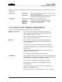
Allows editing previously stored variable names.
RECALL TABLE
Recalls a table previously stored which contains display and trace variables.
A file name must be supplied by the user or selected with the arrow keys for
each of these two functions, after which the
key must be pressed.
2.5.4. FORCED ASSIGNMENTS
During the course of debugging it may become necessary to force a binary value or numerical value a
variable. The FORCED ASSIGNMENT function is provided for this purpose and once activated the
signal name and desired value will be requested and entered via the key pad.
namevariable=expression
press
.
The forced value will not change until an instruction modifies it or until the NC is turned OFF in the
case of non-retained variables.
It is not possible to force input values since they are refreshed at each PLC scan.
2.5.5. FORCED VALUE TABLES
When many variables must be assigned a new value the softkey FORCING FILES in the debug logic
menu is used.
By pressing this softkey the following menu appears:
MEMORY
2-14
FLOPPY
DRIVE
FLASH
MEMORY
EDIT
FORCE FILE
RECALL
FORCE FILE
RENAME
PROGRAM
COPY
PROGRAM
DELETE
PROGRAM
Machine Logic Development (PLC) - Part I (01)
Series S3000
2. Operating procedure
EDIT FORCE FILE
.
RECALL FORCE FILE
Allows editing previously stored variable names.
Recalls a previously stored file which containing display and trace variables.
A file name must be supplied by the user or selected with the arrow keys for each of these two
functions after which the
must be pressed.
2.5.6. RESET STATIC RAM
The static ram may be reset using a softkey contained in the following menu, which is accessed from
the main menu with the DEBUG LOGIC softkey.
ENABLE
PLC LOGIC
DYNAMIC
DISPLAY
GRAPHIC
ANALYZER
By pressing the softkey
PLC LOGIC
MESSAGES
CROSS
REFERENCE
SCREEN
TABLES
ANALYZER
FILES
FORCING
FILES
RESET
SRAM
the static RAM is deleted and the NC restarted.
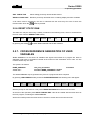
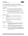
2.5.7. CROSS REFERENCE GENERATION OF USED
VARIABLES
Cross reference is a file where all variables and signals used within PLC program are listed in
alphabetic order with an annotation included at the moment of the declaration and in order the line
numbers where they are used.
The syntax is as follows:
NAME_VARIABLE
<num. line...
>num. line...
num_line_declaration
line where NAME_VARIABLE is written
line where NAME_VARIABLE is read
annotation
The cross reference may be generated only if the PLC program has been compiled.
By pressing LOGIC BEBUG softkey and then CROSS REFERENCE the following menu will appear:
MEMORY
FLOPPY
DRIVE
FLASH
MEMORY
EDIT
CROSS
REFERENCE
SELECT
SOURCE
SELECT
CROSS REF.
RENAME
PROGRAM
COPY
PROGRAM
DELETE
PROGRAM
With the prompt on the active PLC file press CROSS REFERENCE and wait for few seconds.
At the end of this operation press SELECT CROSS REF. a file will be created with the same name as
the PLC program, containing the cross reference.
All the other softkeys have the same function common to all the other environments of NC.
Machine Logic Development (PLC) - Part I (01)
2-15
Series S3000
2. Operating procedure
2.6. PLC TABLE MODIFICATIONS AND DISPLAYS
The variables array (tables to the user) declared internally by the PLC program can be displayed and
modified by the user given that the names are known.
Pressing the softkey OFFSETS / PARAMETERS from the main NC menu accesses the softkey PLC
TABLE. After pressing this key enter the name of the file to be modified then press
.
The array elements and their current values will be displayed side by side it is then possible to change
the values presented and transfer them to the PLC.
2.7. FAST KEYS
By using certain combinations of keys it is possible to quickly access the applications environment from
any menu:
+
to execute programs from memory
+
to activate dynamic display
+
to activate graphic analyzer
+
to access peripherals menu
+
to modify the NC configuration.
+
These keys access a menu to modify dynamically, certain axis parameters
(modified by the PLC- see Part II - System Interface).
The values modified in this environment are applied immediately.
The axis configuration files are updated only when the UPDATE FILE softkey is pressed.
2-16
Machine Logic Development (PLC) - Part I (01)
Series S3000
3. Program organization
3. PROGRAM ORGANIZATION
3.1. GENERAL RULES
The following rules should be kept in mind when writing a program:
•
Each PLC program must have a name containing up to 8 uppercase alphanumeric characters.
The first character must be a letter of the alphabet. The name may not contain blank spaces.
•
PRN, AUX, COM1, COM2, COM3, COM4, LPT1, LPT2, LPT3, LPT4, CON, NUL may not be used
as names for programs.
•
All symbols and variables must be defined by mnemonic names within uppercase alphanumeric
strings up to 6 characters in length.
•
All symbols must begin with a letter and may not contain the following characters:
^ ? ! \ # % & | ~/ ( ) > [ ] < + - * @ = “ ‘ , : . ; blank spaces
Because these are special control characters or are reserved for logic and arithmetic expressions.
The blanks are ignored during compiling of instructions.
•
Words used to describe key functions or system variables may not be used as names.
•
The use of long expressions is discouraged however, it is possible to edit these expressions by
using the $ at the end of the line before starting on the next line.
•
The maximum line length for a logical expression in a PLC program is 500 characters, excluding
blank spaces (these may be tied together on several lines using the $ sign).
•
It is possible to write more than one equation on a single line by separating them with a ";" (semicolon).
•
“LABELS and symbols are always followed by a ":" (colon).
•
The comments within a program may be placed at any position as long as they are preceded by
the "[" symbol. It is recommended that many comments are used to ease of troubleshooting the
program, since they do not occupy extra memory space when the program is compiled.
•
In order to change from the maximum of 6 characters allowed in the definition of variables
(default) to 9 or 12, enter these instructions at the start of the PLC program:
CONST
_MXCHR=6
(or =9, =12)
Machine Logic Development (PLC) - Part I (01)
3-1
Series S3000
3. Program organization
(The default is _MXCHR=6).
It must be remembered when using long names for variables that not only will the source printout
naturally occupy greater space in memory but larger size exec files will also be generated.
3.2. PROGRAM STRUCTURE
Programs are divided into sections and entered in the sequence shown below. Each section must be
preceded by it’s heading:
INP
.......
.......
OUT
.......
.......
INIT
.......
.......
FAST
.......
.......
PROG
.......
.......
END
.......
.......
END
Declaration section
Initialization section
(used only where necessary)
Superfast section
(use only when absolutely necessary)
(if not used remove the key word FAST)
Fast section
(used only where necessary)
Slow section
P
R
O
G
R
A
M
(ordinary logic)
.......
.......
END
Super slow section
.......
.......
.......
Routines section
(used only where necessary)
(used only where necessary)
3.2.1. DECLARATION SECTION
All of the following variables must be declared by name in the order indicated in this section.
Next to the name, it is helpful to insert a brief description of the variable so that the program may be
read and understood by all. For example next to inputs and outputs the connection number and bit
names can be referenced.
The declaration of each group of variables must be made prior to the corresponding key word (see
chapter 4, Initial Declarations).
3-2
Machine Logic Development (PLC) - Part I (01)
Series S3000
3. Program organization
3.2.2. INITIALIZATION SECTION
Initialization is an optional section following the declaration section.
This section, in which inputs and outputs may not be read, allows previously declared variables to be
initialized or reset on power up.
The beginning of the initialization section is recognized by the symbol INIT.
3.2.3. PROGRAM SECTION
This is the section containing the instructions for the PLC to cycle through. This section may be
subdivided into four more sections:
SUPERFAST LOGIC
FAST LOGIC
SLOW LOGIC
SUPERSLOW LOGIC
Superfast logic
The optional SUPERFAST LOGIC section comprises all of the instructions written between the
keywords FAST and PROG. These instructions are intended exclusively for operating on parameters
which change very quickly, and for repetitive acquisitions such as each test of the NC axis position,
(see the configuration documentation). It is necessary to remember that these types of instructions
require ten times more CPU processing time.
If the maximum time limit for this section is exceeded the following message will appear:
Superfast cycle too long.
Fast logic
The FAST LOGIC section is comprised of the instructions written between the key words PROG and
the first END, which are cycled every 10 mSec.
If the maximum time allowed for this section is exceeded the following message will appear:
Fast cycle too long.
Slow Logic
The Slow logic section is comprised of the instructions written between the first and second END.
This part of the program is executed in the time left between the fast logic executions and the time
allotted for the PLC. If this time is not sufficient the Slow section is broken into more cycles.
Machine Logic Development (PLC) - Part I (01)
3-3
Series S3000
3. Program organization
Superslow logic
The SUPERSLOW logic section is comprised of the instructions written between the second and third
END, and are executed with lesser priority for such slower phenomena as (thermal compensation,
message management), and may be further divided into more cycles.
Syncronization
The SUPERFAST, FAST, and SLOW sections are executed in sequence after the INIT section. The
super slow logic is not necessarily in sequence with the others.
The INPUTS are read at the beginning of the superfast cycle, when present, and the OUTPUTS are
written at the end of the same cycle.
If the superfast section does not exist, the inputs are read at the beginning of the fast cycle and the
OUTPUTS are written at the end of the same cycle.
3.2.4. ROUTINES SECTION
Any Routine used only in a certain section (FAST, etc.), can be written directly inside that section. A
routine written for a certain section is often valid for other sections, too, so it is advantageous to write it
at the end of the program, that is, after the third END instruction (see Chapter 6, instruction for
program controls).
3.3. VARIABLE AND NUMBER FORMAT
The program variables may be classified as follows:
BIT:
elementary logic signal with a value of 1 or 0, (true or false)
BYTE:
8 BIT variable containing whole numbers between -128 and 127
WORD:
16 BIT variable containing whole numbers between -32768 and 32767
LONG:
32 BIT variable capable of positive and negative numbers between 1.2 x 10-38 and 3.4 x
1038 in floating point format, with 7 digits in the mantissa.
DOUBLE:
64 bit variables capable of positive and negative numbers between 2.2 x 10-308 and 1.8 x
10307 in floating point format double precision, with 15 digits in the mantissa.
STRING:
a settable variable containing alphanumeric characters in ASCII format.
Decimal numbers may be written in the following format:
± integer.decimal (ex. -12.678)
± integer.decimal e ±exponent in scientific notation (ex. 12.3e-3).
3-4
Machine Logic Development (PLC) - Part I (01)
Series S3000
3. Program organization
Hexadecimal formatted numbers must contain an H suffix and must be preceded by a 0 if the most
significant figure is greater than 9 (ex. 0FA23H).
Similarly the Letter B is used for binary numbers (ex. 01011101B).
For example the decimal number 35 corresponds to 23H in hexadecimal and 00100011B in binary; the
decimal number 195 corresponds to 0C3H in hexadecimal and 11000011B in binary.
For the declaration of variables (numerical and string) see the appropriate sections in chapter 4.
3.3.1. VECTOR AND SINGLE VARIABLES
The (internal) variables of the system are either single or multidimensional arrays. The former
represent only one element while the latter represents many elements under one name. These have
names which begin alphanumerically then are followed by parenthesis which contain a number (called
an INDEX) which identifies the element. The format for the vectorial or matrix variables is as follows:
name (index)
The vectorial variables can be formatted in any of the ways described above. It is obvious that all of the
vectorial variables must be formatted identically, that is (BYTE, WORD, etc.) within each variable.
The index parameter may be:
•
a whole number between 1 and 32767
Example:
TABX(122) = 44.6565
TABX(45)=TABX(77)+TABX(23)
The number 44.6565 is written inside the element 122
The element 45 contains the sum of elements 77 and
23.
• a BYTE variable name between 1 and 127, or a WORD variable between 1 and 32767
Example:
Suppose that the variables BTAB and WTAB have been established as a BYTE and WORD
respectively;
BTAB=18:
TABUT(BTAB)=25:
...
WTAB=199:
VALORE=TABCOY(WTAB):
variable VALORE.
•
18 is written to the variable BTAB
25 is written to the 18th element of TABUT
the value 199 is written to WTAB
the contents of the 199th element of TABCOY are written to the single
an expression which results in a BYTE or WORD format with the same numerical limitations as the
preceding case.
Example:
Suppose that DAT01 and DAT02 are single variables in BYTE format and that ARRAY(x) is a
vectorial variable with more than 11 elements.
DAT01=4
Machine Logic Development (PLC) - Part I (01)
3-5
Series S3000
3. Program organization
DAT02=6
ARRAY(DAT01+DAT02+1)=66 : 66 is written to the 11th element of ARRAY.
In general the vectorial variables occupy contiguous locations within memory, therefor it is important to
pay particular attention to the length and quantity of data handled by these variables to avoid invading
other variable's space. (see further ahead). In fact, if the index value is greater than the number of
elements declared by the VECTOR, they will occupy the next memory location.
Negative Index values, values of zero or values outside the range (ex. 45000) must be avoided
at all costs, else non-related memory locations may be overwritten.
3.3.2. STATIC AND DYNAMIC VARIABLES
Program variables may be static, and maintain their value after the controller is turned OFF, or
dynamic, in accordance with the declaration which was made (see Declaration of Internal Variables in
the next chapter).
Dynamic (numeric) variables assume values of zero when the NC is turned ON, and string values
assume the value (empty string)
COUNTER values are stored during shut-off, however the values for TIMER, PULSE, and SOFTKEY
are not.
Of the internal variables, those associated with the axes positioning (independent and controlled) are
static.
3.3.3. CONSTANTS
It may be useful to describe constants within a program (numerical and string); in these cases the
values are assigned during initialization of the program to avoid repeating the same instructions.
Example:
INIT
SMAX=3500
ALLM= 'SPINDLE OUT OF SERVICE'
The system makes available the following predefined mnemonic symbol:
PI=3.1415927 PI in DOUBLE format.
3.3.4. CONFIGURABLE CONSTANTS FOR MACHINE LOGIC
To utilize machine logic on other similar but not identical machines it is necessary to assign a certain
amount of configurable constants at the time of installation.
This allows for setting parameters, at the PLC level, for lubrication, tool change reports, timer intervals,
axis position, etc..
3-6
Machine Logic Development (PLC) - Part I (01)
Series S3000
3. Program organization
For this purpose the following constants are defined for configuration:
•
16 machine constants common to the whole system called; KMF(1), KMF (2), KMF (3),..,KMF(16) in 32 bit floating point.
•
32 constants called; KMW(1), KMW (2), KMW(3),..,KMW(32) -in word format.
3.3.5. DISPOSITION OF SINGLE BITS INTERNAL TO THE
VARIABLES
The disposition of single bits internal to BYTE, WORD are as follows:
BYTE Format
8
7
6
5
4
3
2
1
Least significant BIT
Most significant BIT
BYTE sign
WORD format
(HI) BYTE
8
7
6
5
4
(LO) BYTE
3
2
1 16 15 14 13 12 11 10
9
Least significant BIT
Most significant BIT
WORD sign
Note:
BYTE and WORD are used by the PLC in signed binary format; that is negative numbers are
represented in 2's complement.
Example:
BYTE
1
-1
=
=
0 0 0 0 0 0 0 1 B
1 1 1 1 1 1 1 1 B
sign bit
WORD
1
-1
=
=
0 0 0 0 0 0 0 0 0 0 0 0 0 0 0 1 B
1 1 1 1 1 1 1 1 1 1 1 1 1 1 1 1 B
sign bit
Machine Logic Development (PLC) - Part I (01)
3-7
Series S3000
3. Program organization
3.3.6. ACCESS TO VARIABLE BITS
Single Variables
To access the bits within a variable the variable is treated as an eight element matrix if it is a BYTE, or
16 element matrix if it is a WORD, etc.The following matrix syntax is used:
var(index)
index may be one of the following lengths (in the examples the variables are single and not vectorial):
•
An integer between 1 and the maximum number of bits for that variable.
Example:
BIT3=NUMBT(3) with this function, BIT3 will equal 1 or 0 depending on the state of the third bit in
NUMBT.
•
the name of a variable of the type BYTE or WORD which may assume values between 1 and the
maximum number of bits to be operated on.
Example:
INDEX=5
BYTE1(INDEX)=1
•
puts a 1 in bit 5 of BYTE1
an expression resulting in the BYTE or WORD format with the same limits as the previous case
Example:
DATO1=8
DATO2=6
WORD1(DATO1+DATO2+1)=0
format.
places a 0 in the 14th bit of the variable WORD1 in word
In each case it is necessary to remember that, if the value of the index exceeds the formatted value,
memory locations adjacent to the locations of the variable will be overwritten, these may presumably
be occupied by other variables.
Index values of zero must be avoided, as should negative values and out of range values as
described above.
Vectorial variables
In the case of vectorial variables, if a bit from a vector element must be read it is easier to copy the
empty element to a dummy variable, thereby accessing only the single bit.
3-8
Machine Logic Development (PLC) - Part I (01)
Series S3000
3. Program organization
Example:
Suppose that the variables CONFI(X) and TEMPOR are WORD types
The 2nd element of CONFI is copied to TEMPOR
the variable BIT12 equals the 12th bit in TEMPOR.
TEMPOR=CONFI(2)
BIT12=TEMPOR(12)
If, instead, a single bit of a vector element is to be written, it is necessary to first write the bit to a
dummy variable and then overwrite the element of the vector with it. For more information on bit
handling see chapter 5, Functions and Operations.
3.3.7. ACCESS TO BITS OF ADJACENT VARIABLES
If the index value exceeds the formatted value, as described earlier, the adjacent bits will be
overwritten as follows:
Examples:
Suppose the variables VAR1, ALARM, and CONFIG are BYTE types and that VAR2 and FLAGS are
WORD types; the following bits are accessed (in bold) with the expressions shown on the right:
VAR1
8
7
6
5
4
3
2
1
VAR1 (3)
ALARM
8
7
6
5
4
3
2
1
VAR1(10)=ALARM(2)
CONFIG
8
7
6
5
4
3
2
1
HI VAR2
8
7
6
5
4
3
2
1
LO VAR2
16
15
14
13
12
11
10
9
HI FLAGS
8
7
6
5
4
3
2
1
LO FLAGS
16
15
14
13
12
11
10
9
Machine Logic Development (PLC) - Part I (01)
VAR2(3)
VAR2(18) = FLAGS(2)
3-9
Series S3000
3. Program organization
3-10
Machine Logic Development (PLC) - Part I (01)
Series S3000
4. Declarations
4. INITIAL DECLARATIONS
All of the symbols used in the PLC program must be declared at the beginning of the program using
one of the following keywords described in greater detail further ahead in this chapter.
INP
TERM
OUT
TERM
SRAM
RAM
STR
EQU
PULSE
FTIMER
STIMER
COUNT
LANG
SOFTK
physical input
skip unused inputs
physical output
skip unused outputs
variable stored in non-volatile RAM (not lost when power is lost)
variable stored in volatile RAM. (lost when power is OFF to NC)
string
equivalence or synonym
derived impulse
fast timers
slow timers
counters
languages of the sotfkeys
softkey
NOTE:
Not all of the declarative functions listed above are required but when used must appear in the
order shown.
Also when variables of different data format sizes are used they must be declared in order starting with
the larges format.
Example:
SRAM,64
NOMEA
...
RAM,32
NOMEF
...
SRAM,16
NOMEL
...
SRAM,8
NOMEP
...
the names which follow are in DOUBLE format
the names which follow are in LONG format
the names which follow are in WORD format
the names which follow are in BYTE format
Machine Logic Development (PLC) - Part I (01)
4-1
Series S3000
4. Declarations
4.1. DECLARATION OF PHYSICAL INPUTS / OUTPUTS
The program must always begin with the declaration of the inputs and outputs physically connected to
the unit.
Inputs and outputs are referenced directly to their physical I/O board terminations. For example the first
input declared after the INP keyword is assigned to terminal 1, the second to terminal 2 etc.
For input wires the key word INP must be used in the following format:
INP[,attribute][,connector number]
Input Name 1
...
Input Name n
For output wires the keyword OUT must be used in the following foprmat:
OUT [,attribute] [,connector number]
Output name 1
...
Output name n
Where:
[,attribute]
defines the type of variable;
,1 describes 1 bit (default value when attribute omitted)
,8 describes a byte
,16 describes a word
[,connector number]
indicates the position on the I/OMIX board where the connector is
located* (see system Installation Manual).
*The default is 1 if this parameter is omitted.
After declaring the types of inputs/outputs a list of all the variable names for those types must be made.
Example:
INP
NOMEA
NOMEB
NOMEC
OUT
NOMED
NOMEE
name of input 1
name of input 2
name of input 3
name of output 1
name of output 2
This determination assigns three names to the first three inputs and two names to the first two outputs
all are bit types.
The I/O expansion boards follow the same rules as the main I/O board.
Example:
Configuration:
4-2
-1 I/OMIX board in slot 1
-2 Digital I/O expansion boards (I/OD)
Machine Logic Development (PLC) - Part I (01)
Series S3000
4. Declarations
In this case the declaration of the INP must be:
INP[,attribute ][,1]
NAME1
NAME2
...
NAME96
input number 1 on main board
input number 96(last input) on the second expansion board
The numbering and configuration of the I/O on each board is described in the Installation Manual.
Instead, in cases where a group of 8 or 16 signals exist which must be treated as a single unit, it is
helpful to define them as a BYTE or a WORD. In such instances, to access a single signal from the
group the rules for the access to variable bits apply (see access to variable bits in the preceding
chapter).
Example:
INP,8
NAME
or:
INP,16
NAME
In general it is possible to have a double declaration for mixed treatment via a syntax of the type:
group:[name1][,name2][,...][,namen]
Where group refers to the group of signals and name1...namen refer to the single bits with n being
limited by the length of the description and can be no greater than 8 per BYTE or 16 per WORD.
All of the terms following the group name (name1..namen) are optional. This mean that any element
may be omitted from the list including terms from the right and terms from the left.
In the cases where no intermediate names are given, the names can be omitted but the corresponding
comma must be kept. A comma is not needed after the last name. The compiler automatically
truncates the signal description at that point.
Example:
INP,8
INGR1:LIVOIL,IPLUBE,,,TERMAX,TERMAY
Sometimes there are gaps in the physical sequence of input or output connections. In this case it is
necessary to define the number of the last non used terminal with the function TERM, and continue by
declaring all remaining signals. The format for said function is as follows:
TERM,number
If number is a bit it may take any value, however if it is a BYTE it must be a multiple of 8, and a
multiple of 16 if it is a WORD.
Machine Logic Development (PLC) - Part I (01)
4-3
Series S3000
4. Declarations
Example:
INP
IFCXP
[input1
TERM,5
ISPOK
[input6
For the listing above, the terminals from 2 - 5 are not used, and the program restarts from the 6th
terminal with the signal ISPOK.
If the parameter “I/O access diagnostic” is enabled in the installation setup, if you attempt from PLC or
logic debugging to access in read or write a resource that is not present, the following message
appears: "E1994: access to missing component" followed typically by the number of the PLC line
where the inconsistency was found.
The diagnostic checks for consistency between the addressing and that resources accessible from
PLC are actually present (i.e., digital inputs and outputs, analog inputs and outputs, heat probes).
4.1.1.
PHYSICAL INPUT/OUTPUT DECLARATION: REMOTE I/O
MODULES
To address the digital I/O on remote modules, use the extended INP or OUT declaration, followed by a
list of the Names of the variables.
For the INPUT terminals, use the INP declarative with the following format:
INP,attribute,master board number,slave number
input 1 name
...
input n name
and for the OUTPUT terminals:
OUT,attribute,master board number,slave number
output 1 name
...
output n name
Where:
attribute
Defines the input type. May be:
,1 describes 1 BIT only (default value if attribute omitted)
,8 describes a BYTE
,16 describes a WORD
master board number
indicates which BOARD SLOT the board with RIO master interface will
have, like the case of local I/O where it relates to the I/OMIX board. If the
master board with integrated RIO is used, the board number will be 17.
slave number
declares the address set with the microswitches on the remote module.
Example:
INP,1,17,60
NAMEA
NAMEB
NAMEC
OUT,1,17,60
NAMED
NAMEE
4-4
bit format input, master17, slave 60
name of input number 1
name of input number 2
name of input number 3
bit format output, master17, slave 60
name of output number 1
name of output number 2
Machine Logic Development (PLC) - Part I (01)
Series S3000
4. Declarations
4.2. DECLARATION OF INTERNAL VARIABLES
Internal variables are defined as those variables or signals needed for calculations or internal storage
not directly connected to the physical signals.
Depending on whether or not the variable must be retained after shutting off the NC, two types of
variables may be declared:
SRAM[,attribute]
Internal variable1
...
Internal variable n
variables to be retained
RAM[,attribute]
Internal variable 1
...
Internal variable n
variables not to be retained
where;
[,attribute]
,1
,8
,16
,32
,64
may assume the following values via the declarative:
to indicate a variable of BIT format (value of default, if omitted)
to indicate a variable of BYTE format
to indicate a variable of WORD format
to indicate a variable of LONG format
to indicate a variable of DOUBLE format
Besides the types RAM,x and SRAM,x, there is also the possibility of managing variables, called
SSRAM, which are not reset by the usual NC reset operations or by recompiling the PLC.
The SSRAM can be given the same sizes as the normal SRAM.
Example:
SSRAM,16
ORELAV
[machine working hours counter
The space available for the SSRAM is very limited (96 bytes); the area relative to these variables is
reset when a PLC is compiled with inside an SSRAM declaration different from the previous one.
S1200
In the S1200 variables declared as (RAM [,attribute]) were implicitly retentive
Vector arrays (tables) may also be used as for internal variables, in all formats except bit format.
Therefore we have:
name(number):[name1][,name2][,....][,namen]
number indicates the vector index. If the vector has a certain dimension previously declared, the
names to the right of the ":" indicate the names of each element in the same format as the vector.
In case some names are not given, it is necessary only to leave the commas in their places.
Commas are not needed after the last name; the compiler truncates the signal description at that point.
Machine Logic Development (PLC) - Part I (01)
4-5
Series S3000
4. Declarations
The number of vector elements may be as high as 32767 depending on the amount of memory
available.
As was said earlier, the LONG and DOUBLE variables, being of floating point format, are always used
for mathematical calculations.
4.3. DECLARATION OF STRINGS
Strings are variables which contain alphanumeric characters in ASCII format. Generally the declaration
is used for storing messages.
The declaration of string names is effected after the key word:
STR[,attribute]
String variable 1
...
String variable n
where:
[,attribute]
,16
,32
,64
,128
,256
may assume the following values:
for strings with a maximum length of 14 characters
for strings with a maximum length of 30 characters
for strings with a maximum length of 62 characters
for strings with a maximum length of 126 characters
for strings with a maximum length of 254 characters
The default value is 64 in cases where the attribute is omitted. If an attempt is made to write a string
longer than the declared length, it is automatically truncated and an error message is shown on the
display.
It is possible to use vectorial declaratives even for strings:
•
Using the explicit format the name of every attribute is listed:
STR
NAMEA
NAMEB
•
Using a matrix type format the name and total number of elements are specified:
STR
NAME(n)
Example:
...
STR,64
NAMEA
MSG(12)
...
PROG
...
NAMEA='SAMPLE MESSAGE'
MSG(2)='SPINDLE PROTECTION STOP'
....
4-6
assign contents of variable string NAMEA
assign contents of vector variable string MSG(2)
Machine Logic Development (PLC) - Part I (01)
Series S3000
4. Declarations
4.4. DECLARATION OF EQUIVALENCES
Using equivalence, different names may be assigned to variables already defined in earlier
declarations.
The equivalence function is as follows:
EQU[,attribute]
name1:name2
...
namem:namen
where the format of the variable being introduced is declared by the value of the attribute and
therefore may assume all permissible values for internal variables (1, 8, 16, 32, 64).
The assignments which follow must be of the type:
namex:namey
where namex is the new symbol to insert and namey is a quantity that must have been already
declared.
Example:
RAM,8
ARRAY(10)
...
EQU,8
NAMEX:ARRAY(3)
The new variable NAMEX describes the third byte of ARRAY, which was
defined earlier as having 10 elements
[
EQU,16
WORD:ARRAY(1)
the variable WORD refers to the first two bytes of ARRAY.
In addition to the syntax of the preceding example it is possible to declare a new vector operand.
Example:
RAM,16
OLDVAR
EQU,8
NEWVAR(2):OLDVAR
Where NEWVAR(2) is a two element vector of BYTE format
in which NEWVAR(1) is equivalent to the upper part of OLDVAR
and
NEWVAR(2) is equivalent the lower part of OLDVAR.
OLDVAR
upper part of OLDVAR
NEWVAR(1)
Machine Logic Development (PLC) - Part I (01)
lower part of OLDVAR
NEWVAR(2)
4-7
Series S3000
4. Declarations
By way of the declarative EQU, equivalences can be assigned between string variables and byte
vectors.
This is a useful feature if wishing to dispose of a vector containing the ASCII characters of a given
string.
Es.
STR
BUFSTR
[
EQU,8
VETSTR(64):BUFSTR
[
PROG
BUFSTR='ABCD'
[
[VETSTR(1)=0
[VETSTR(2)=4
[VETSTR(3)=65
[VETSTR(4)=66
[VETSTR(5)=67
[VETSTR(6)=68
[VETSTR(7)=XX
[string variable
[I associate a 64 byte vector with the string
[this byte is always at 0
[the second byte contains the string length
[ASCII code for letter A
[ASCII code for letter B
[ASCII code for letter C
[ASCII code for letter D
[... other
4.5. PULSE
The pulse function is derived from the rising edge of a signal. Its purpose is to create an impulse seen
only once by every logic equation. It is enabled at the beginning of the slow logic section when the
generating equation or variable changes from a "zero" (0) logic level to a high logic level (1), and is
reset when the slow logic section is completed.
Pulses programmed in the fast logic sections do not terminate until all logic sections have been
executed. It is necessary that the generating variable lasts the minimum capture time to activate an
impulse equal to a complete scan of all the logic. This will ensure that the pulse is also detected in the
slow logic section.
For the technique of synchronization described, consider that the rising edge of the pulse generally
does not overlap the rising edge of the generating signal, but instead lags it by a time period which may
equal or exceed a complete scan of the PLC program.
Note: The pulses are not retentive, therefore when the NC is turned ON, if they are associated
a signal already at a 1 state (eg: an input), they will generate a pulse.
with
The equation declaring a PULSE is written as any other signal in the program. For easy identification
signal names should be derived from the name of the signal that triggers them (eg: Pstart for a pulse
generated by the signal START). Pulses are declared in the same way as any other signal.
Up to 64 PULSES may be defined in the declaration section, using syntax:
PULSE
namea
...
namen
4-8
Machine Logic Development (PLC) - Part I (01)
Series S3000
4. Declarations
Example:
PULSE
NAMEA
NAMEB
...
...
PROG
NAMEA=(NCMD=5)
...
NAMEB=EMEA
the namea signal is an NC pulse in manual mode
the nameb signal is an NC pulse in Emergency mode
4.6. TIMERS
There are 32 fast timers available to the user, with a base time of 10 mSec (one cycle), capable of
counting up to 327.67 seconds, and there are 64 slow timers with a base time of 100 mSec (10
cycles), capable of counting up to 3276.7 seconds (about one hour).
Timers are declared as such in the declaration section of the program, however their duration must be
declared inside the program at the points where they are used.
Timers must be defined after the declarative FTIMER (fast timer) or STIMER (slow timer) by the
following syntax:
FTIMER (or STIMER)
input, output, derived, stop, count
...
input, output, derived, stop, count
or
FTIMER (or STIMER)
input, output
input, output
where:
input
is the name of the signal that activates the timer
output
is the name of the time delayed output signal
derivedis the name of the signal that is active during the delay time
stop
is the name of the signal that can be used to freeze the count
count
is the name of the WORD which contains the current count
Machine Logic Development (PLC) - Part I (01)
4-9
Series S3000
4. Declarations
The functional display of the timer is as follows:
Count
Input
Stop
xTIMER
Output
Derivative
Input
output
Derivative
Stop
Count
module
Count
Note:
The timer output remains high (1) as long as the input is high.
INPUT I
f equal to 1: the timer counts according to its base time.
If equal to 0: the output is zeroed, but the count value is left unchanged. The timer
counter is reloaded when the input changes from 0 to 1.
STOP
With the transition from 0 to 1 the values are frozen and the timer is disabled. With
the transition from 1 to 0 the timer restarts from the point where it was frozen.
OUTPUT
Goes to 1 when the set time has elapsed.
Returns to 0 when the input goes to 0.
Is at 1 during the counting interval
DERIVATIVE
All timer variables may be read and written from the program, with the exception of the output (U) and
derived signals (D) which may only be read.
The time parameter, which does not have to be defined in the declaration section, is assigned in the
program section of the code when the timer function is used.
This allows timer functions to be modified during the course of the program using fixed or parametric
timing.
To make the timer signals identical in any part of the program, they must be synchronized to the signal
which defines their input. This implies that the condition of the timer output as well as its derivative, are
updated only when the PLC program reads the timer input instruction.
The syntax for activating a timer within a program is as follows:
input(count modules)=expression
4-10
Machine Logic Development (PLC) - Part I (01)
Series S3000
4. Declarations
where the count modules may be:
- a number between 1 and 32767
- a BYTE or WORD variable with contents ranging from 1 to 32767
- an expression that results in a BYTE or WORD with the same range as above
Example 1:
FTIMER
T1I,T1U,T1D,T1A,T1W
T2I,T2U,T2D,T2A,T2W
....
PROG
T1I(25)=....
T2I(2*TIMBAS+10)....
...
declaration of timer 1
declaration of timer 2
timer 1 set to 250 mSec fixed.
timer 2 set as a function of TIMBAS
Example 2:
OUT
U1
STIMER
T2I,T2U,T2D,T2A,T2W
...
PROG
T2I(10)='“2U
U1=(T2W<5)
oscillator output
declaration of timer 2
timer 2 set to oscillate with 1 sec base time
square wave output with 1 sec period
4.7. COUNTERS
There are 48 up/down counters with programmable modules between 2 and 32767.
The counters, like the timers, must be defined in the declaration section, however the modules or
quantity to be counted, must be defined inside the program. The declaration format is as follows:
COUNT
zero,forward,reverse,carry,count
zero,forward,reverse,carry,count
where:
zero:
forward:
reverse:
carry:
count:
is the name of the signal which zeroes the counter
is the name of the signal which advances the counter
is the name of the signal which reverses the counter
is the name of the signal generated by the counter when passing zero
is the name of the WORD containing the cumulative count
The functional block diagram is:
Count
Forward
Reverse
Zero
COUNTER
Machine Logic Development (PLC) - Part I (01)
Carry
4-11
Series S3000
4. Declarations
The counter functions as follows:
zero:
forward:
reverse:
carry:
the count value goes to 0 when this signal changes from 0 to 1
the counter increments at each rising slope of this signal
the counter decrements at each rising slope of this signal
signals that the counter has passed through zero (ie that an OVERFLOW or
UNDERFLOW occured).
The following figures illustrate both forward and reverse operation of a counter with modules 10.
Forward count
Zero
Forward
Count pos.
Carry
1 0 0 0 0 0 0 0 0 0 0 0 0 0 0 0 0 0 0 0 0 0 0 0 0 ...
0 1 0 1 0 1 0 1 0 1 0 1 0 1 0 1 0 1 0 1 0 1 0 1 0 ...
0 1
2
3
4
5
6
7
8
9
0
1
2 ...
0 0
0
0
0
0
0
0
0
0
1
0
0 ...
Reverse count
Zero.
Reverse
Count pos.
Carry
1 0 0 0 0 0 0 0 0 0 0 0 0 0 0 0 0 0 0 0 0 0 0 0 0 ...
0 1 0 1 0 1 0 1 0 1 0 1 0 1 0 1 0 1 0 1 0 1 0 1 0 ...
0 9
8
7
6
5
4
3
2
1
0
9
8 ...
0 0
0
0
0
0
0
0
0
0
1
0
0 ...
During the forward count when the counter arrives at the module value the count is automatically set to
zero. In the reverse count after arriving at zero the module value is loaded into the counter.
In these cases the zero transition is signalled by activation of the carry signal.
All of the signals named in a counter declaration may be read or written from within the program ,
except for the carry signal which may only be read.
The count parameter does not have to be defined in the declarative section, however it must be
assigned in the program in the statement that sets the counter to zero.
This makes it possible to modify the counter action in the course of the program and allows fixed or
parametric functions to be implemented.
The count module is loaded when the zero signal is released.
Example:
INP
ICOMAI
crib reverse input count
COUNT
C1Z,C1A,C1I,C1R,C1C
declare counter 1
C2Z,C2A,C2I,C2R,C2C
declare counter 2
...
PROG
C1Z(50)=...
applies counter 1 with module count 50
C1I=ICOMAI
crib reverse input count decrements the counter
...
C2Z(TEMPO/60)=...
applies counter 2 defined by the variableTEMPO
4-12
Machine Logic Development (PLC) - Part I (01)
Series S3000
4. Declarations
4.8. LOGIC DEFINABLE SOFTKEYS
The system has 8 available function keys positioned vertically and located to the right of the display,
which can be entirely defined and controlled by the machine logic and accessed by the function keys
and
. In this way it is possible to enhance the man / machine interface via the menu for
functions usually performed by switches and lamps, etc.., normally requiring additional NC inputs and
outputs to connect these controls.
A softkey is treated by the system as an illuminated switch with a label.
Once the variables 'switch' and 'lamp' and the 'label' text are declared, the display will contain a new
function key with the desired label capable of sending signals to the PLC, and also capable of being
lighted by the PLC when in use.
There are 128 possible softkey combinations and are defined in groups of up to 8 menu elements,
identified by the declaration SOFTK. The softkeys related to the same menu are displayed
simultaneously and to change from one menu to the next an index attribute must be named or a PLC
variable must be declared called (SFKMEN).
The 'switch' signal may be momentary or continue for as long as the key is selected (pressed).
The softkeys may also be associated with a message or numerical string, to aid the operator with
accessing data.
The easiest way of declaring a softkey menu is:
SOFTK,menu number
switch,lamp[,0/1],'label(text)'
...
switch,lamp[,0/1],'label (text)'
selecting ,0
selecting ,1
indicates the switch is momentary and lasts only one PLC execution cycle
(default).
indicates the switch is on as long as it is pressed.
Menu number may be omitted when declaring the first menu.
Softkeys associated with messages or numerical variables
The definition of a softkey associated with a message or numerical variable is:
strobe,lamp,[switch,]'label','message',[FP:/STR:]variable[,default value]
In this example the switch signal is received by the PLC as soon as the softkey is pressed followed by
the
key. The message is subsequently displayed on the screen followed by the actual value of
the associated variable. The strobe signal is sent to the PLC to signal a new variable value or to
confirm the existing one.
The variable is implicitly defined as DOUBLE format (FP:) as long as there are no other specifications
via the string format STR:
The default value, when defined, is always displayed on the command line in place of the current
variable value when the softkey is pressed. It is not intended to be an initialization value for the variable
when the NC is first turned ON.
Machine Logic Development (PLC) - Part I (01)
4-13
Series S3000
4. Declarations
SOFTKEY for menu call
When a softkey must call the next menu or return to the previous one, the syntax for creating the chain
is as follows:
switch,lamp,'label',menu number
An alternative to this method is to select the softkey menu directly by writing the number into the PLC
variable SFKMEN.
This variable always contains the softkey menu number currently displayed, even when the menu
change is effected automatically.
The respective formats for text descriptions are 18 characters on three lines for labels and 20
characters on the command line for messages. The message text may contain all characters except
the quotes (" ").
Example:
SOFTK,1
P1,L1,1,'JOG X +'
...
P7,L7,0,’REFERENCE AXIS'
P8,L8,'DISPLACEMENT',2
SOFTK,2
first softkey menu
the label is JOG X + and the switch is on while pushed
the 7th softkey label is zero search & the switch is momentary
the softkey with label DISPL calls the 2nd softkey menu
second softkey menu
P21,L21,1,'DISPLACE AXIS X' first softkey of the second menu...
4.9 SOFTKEY AND MESSAGES WITH MULTILINGUAL TEXT
Sofkeys managed by PLC (
-
) may be defined as “multilingual” mode in order to automatically
adjust themselves to the selected language for the menus of NC (
-
).
Before SOFTK definition, in the declaration section of PLC, it must be introduced the following
instruction:
LANG, cod_lang_1[, cod_lang_2] [...] [, cod_lang_5]
where language codes may be:
1=
2=
3=
4=
5=
6=
4-14
Italian
French
German
English
Spanish
Portuguese
Machine Logic Development (PLC) - Part I (01)
Series S3000
4. Declarations
In the declaration of menus the label for each softkey must be specified together with microedit text in
all the required languages following the declaration of LANG with the syntax shown:
Example:
Italian and English messages:
LANG,1,4
...
SOFTK,1
P01,L01,’ volantino X ’ ‘ handwheel X ’
P02,L02,’ tempo lubrif. ‘ ‘ lubrif. time ‘,’ minuti= ‘ ‘ minuts= ‘, TIME
P03,L03,’ parola chiave ‘ ‘ password ‘,’ inserisci= ‘ ‘ insert= ‘, STR:CHIAVE, ‘ manutenzione ‘ ‘ service’
The variable SFKLNG (written from NC) contains the code indicating the active language on the NC.
By testing this variable it is possible to organizing the PLC program in order to initialize the string
variables to display multilingual messages.
Language codes are the same of those used in the declaration of LANG.
Example:
...
INIT
IF (SFKLNG<>1) ENGL
[Initialization Italian messages
MSG(1)=‘ EMERGENCY STOP’
MSG(2)=‘ FAULT ON SPINDLE DRIVE‘
...
ENDMSG
[
ENGL : $
IF (SFKLNG<>4) ENDMSG
[Initialization English messages
MSG(1)=‘ EMERGENCY STOP ’
MSG(2)=‘ FAULT ON SPINDLE DRIVE ‘
[
ENDMSG : $
...
Machine Logic Development (PLC) - Part I (01)
4-15
Series S3000
4. Declarations
4-16
Machine Logic Development (PLC) - Part I (01)
Series S3000
5. Operations and functions
5. FUNCTION AND OPERATION
5.1. PROGRAMMING WITH ELEMENTARY LOGIC
The first logical network encountered in any PLC application is a combination of closed and open
contacts representing true or false signals that activate an output.
For example take the electrical schematic below:
DRAOK
MAREG
COMAS
TEST
To describe the function of the logic network shown above it can be said that the output COMAS is
active when DRAOK and MAREG are true (closed) or TEST is false.
In PLC S3000 language this is written as:
COMAS=DRAOK&MAREG~"TEST
Where the elementary logic operators are:
&
~
|
"
AND
OR
XOR
NOT
When applying the logic operators it is necessary to remember that AND and XOR have a higher
priority than OR.
In the equation U=A~B&C it is evaluated as U=A~(B&C).
If instead it is desired to OR A with B and then AND the result with C, this is written as U=(A~B)&C
The parenthesis changes the priority of the operations, as in conventional arithmetic.
Machine Logic Development (PLC) - Part I (01)
5-1
Series S3000
5. Operations and functions
Logic operators may be applied to signals, bits, bytes, and words. Expressions are evaluated for bit to
bit correspondence. Therefore the operands in the same equation must be of the same type.
Example:
RAM,16
CONFI(3)
[declares an array of 3 16 bit variables
TEMPOR
[tempory storage used for bit manipulation
...
PROG
[example to invert the 4th bit of the first element in the array CONFI()
TEMPOR=CONFI(1)
IF(TEMPOR(4)) TEMPOR(4)=0;CONFI(1)=CONFI(1)&TEMPOR;END [reset bit 4
IF("TEMPOR(4)) TEMPOR(4)=1;CONFI(1)=CONFI(1)~TEMPOR
[set bit 4
END:$
...
5.2. ARITHMETIC OPERATIONS
May be applied to byte, word, double and long formats.
The typical syntax format is:
result=operand operator operand [...][operator operand]
possible operators are:
+
addition
subtraction
*
multiplication
/
division
//
division remainder
Example:
(10.5//7)=3.5
If this operation is made on bytes or words the result will be an integer remainder.
The // operation can be used to extract the decimal portion of a floating point number by dividing it by
1.0
Example:
(4.123//1.0)=0.123
Operators and parenthesis have the same priorities as in traditional arithmetic.
IMPORTANT: If the result of an operation results in a number greater than the size of the variable, it is
converted to its 2's compliment.
The result of a division by 0 results in the maximum positive number for the variable.
If overflow, underflow, and division by 0 occur during program execution the system displays an
appropriate error message (see Part II - List of Preset Signal and Registers).
5-2
Machine Logic Development (PLC) - Part I (01)
Series S3000
5. Operations and functions
5.3. FLOATING POINT MATHEMATICAL FUNCTIONS
The following functions may be used on single, double, and long formatted variables. Trigonometric
functional units are degrees.
SQR
INT
NEI
SIN
COS
TAN
ATN
LOG
LGT
ACS
ASN
NEG
SGN
(argument)
(argument)
(argument)
(argument)
(argument)
(argument)
(argument)
(argument)
(argument)
(argument)
(argument)
(argument)
(argument)
operand^operand
ABS
(argument)
Note:
square root
truncated integer
rounded integer
sine
cosine
tangent
arctangent
logarithm
logarithm base 10
arccosine
arcsine
change sign
substitutes a value in the format of the operand equal to 1 if the sign
is positive and -1 if it is negative.
raise to a power
supplies the absolute value of a byte, word, long or double formatted
variable.
in the case of raising to the power of 2, it is more efficient, in terms of execution
speed, to use the syntax argument*argument instead of argument^argument.
5.4. COMPARE
It is often necessary to compare two variables or a variable and a constant value and then operate on
the result.
Comparisons may be made using the following symbols:
=
<>
>
<
<=
>=
equal to
not equal to
greater than
less than
less than or equal to
greater than or equal to
The comparison expression must be contained within parenthesis and may therefore be used as a
logic element within an equation.
Example:
MAOR=(AUXM=3)~(AUXM=13) [MAOR is true when AUXM=3 or when AUXM=13
This function can be used for Bytes, Words, etc.. provided the equation is homogeneous.
It cannot be used for strings. To compare two strings the function STRCMP() must be used.
Machine Logic Development (PLC) - Part I (01)
5-3
Series S3000
5. Operations and functions
5.5. ROTATION
This function can be performed on byte and word variables - BIT, LONG, and DOUBLE formats are not
allowed. The operand @ is used followed by the number of rotations to be effected.
variable@ + n
variable@ - n
effects a left Rotation
effects a right Rotation
where n, is the number of rotations in BYTE or WORD format.
A left rotation moves all of the bits in the direction of the most significant bit, while the most significant
bit moves into the least significant bit location.. Right rotation performs the opposite function.
Example:
STATP = STATP @+1
effects a left rotation of one position per bit.
Before rotation
1
0
0
0
1
0
0
0
After rotation
0
0
0
1
0
0
0
1
5.6. FORMAT CONVERSIONS
Aset of functions are provided for converting an input variable to an output variable with a different
format.
The syntax is the same for all functions:
output=function(argument)
where: argument may even be a complex expression.
ENC - search bit
Scans the argument value starting from the least significant BIT, and produces an output that
indicates the position of the first bit that is set to a 1. The output is 1 to 16 if the argument is a WORD
or 1 to 8 if it is a BYTE.
Example:
ENC (10100000B) = 6
5-4
Machine Logic Development (PLC) - Part I (01)
Series S3000
5. Operations and functions
DEC - Set bit
Outputs a BYTE or WORD with a 1 in the bit position corresponding to the value of the argument,
provided the value does not exceed 16 for words or 8 for bytes.
Example:
DEC (7) = 01000000B
since the number is 7, the seventh bit of the output word is set to a 1.
HI - Extracts the high byte from a word
Converts the eight highest bits in the argument word into a byte (argument).
Example:
BYT1=HI(WORD1)
extracts the upper portion of WORD1
LO - Extracts the low byte from a word
Converts the eight lowest bits in the argument word into a byte (argument).
Example:
BYT1=LO(WORD1)
extracts the lower portion of WORD1
EXT - Conversion of a byte into a word
Extends a byte (argument) into a word with sign preservation. In other words, if the sign bit (bit 8) was
0 it adds eight zeroes to the left; if it was 1 it adds eight ones to the left.
Example:
WORD2=EXT(BYTE1)
BCD - Converts a binary number to BCD
Converts a byte (argument) into a two digit BCD number or a word(argument) into a 4 digit BCD
number.
Example:
BCD1=BCD(BYTE1)
if BYTE1 was equal to 00001100 (12 decimal), BCD1 would
be 0001 0010
BIN - Converts a BCD number to a byte or word
Converts a two digit BCD number contained within a byte, or a 4 digit BCD number contained within a
word back into binary format. Hence it is the opposite of BCD.
Machine Logic Development (PLC) - Part I (01)
5-5
Series S3000
5. Operations and functions
Example:
BYTE1=BIN(BCD1)
if BCD1 was equal to 0001 0010, BYTE1 would be 00001100
IFP - Converts a byte or word into floating point format
This function is necessary for executing mathematical operations on bytes and words which are
reserved for floating point variables.
Example:
NUTF=IFP(DTOOL)
converts DTOOL variable into floating point
FPI - Converts floating point format into byte or word
5.6.1. COMPLEX EXPRESSIONS
The functions described above for the transformation between various formats may be used in
conjunction with the arithmetical and mathematical functions to form complex expressions.
However, not all of the functions are useful in complex expressions. In particular the following complex
expressions are not allowed.
•
Functions with more than one argument:
FF(..),(..), MUX(..),(..),
RIC(..)
•
Functions with string arguments:
VAL(...), LEN(..),
INSTR(..),STRCMP(..)
The following are examples of valid complex expressions
Example 1:
RAM,8
ANGLE
RAM,32
RESULT
...
RESULT=SIN(IFP(ANGLE*2+45))
the result of the expression ANGLE*2+45 is
converted to floating point and then the sin of that
value is taken.
Example 2:
POWER=OFFSET+SIN(1/FREQ*TIMBAS)+COS(ANGLE)
Power is equal to the sum of offset and the cosine of ANGLE plus the sine of the expression
1/FREQ*TIMBAS
5-6
Machine Logic Development (PLC) - Part I (01)
Series S3000
5. Operations and functions
5.7. STRING OPERATIONS
A string is an array of alphanumeric characters excluding commas.
5.7.1. NUMERICAL FUNCTIONS WITH STRING ARGUMENTS
These are functions resulting in a numerical value starting with a string arguments:
VAL - Transforms an ASCII format to a numerical value
Supplies the numerical value of a string variable. The syntax is:
VAL(argument)
where argument may be:
- a string variable
- an expression which results in a string variable
The output of this function may be in BYTE, WORD, LONG, or DOUBLE format. The output format
selected must be compatible with the length of the string argument that is to be converted.
The conversion stops at the first non-numerical character.
Example:
RAM,32
NUMVAL
STR
NUMSTR
...
PROG
NUMSTR='123.56'
NUMVAL=VAL(NUMSTR)
[NUMVAL contains the numerical conversion of NUMSTR
[ which is NUMVAL=123.56
INSTR - Search for a string within a string
Searches for a string within another string, starting from a specified position and for a specified length.
It supplies the position at which the first character of the string was found. The format is:
INSTR(argument1,argument2,argument3,argument 4)
where:
argument1
argument2
argument3
is the string within which the search takes place
is the string to be found
is the position from which to begin the search
Machine Logic Development (PLC) - Part I (01)
5-7
Series S3000
5. Operations and functions
argument4
specifies how many characters in argument 2 must be searched through
starting from argument 3
argument1 and argument2 may be:
- a sequence of characters delimitated by inverted commas
- a string variable
- an expression whose result is a string
argument3 and argument4 may be:
- an integer between 1 and 255
- a byte variable with a value between 1 and 127 or a word variable with a value between 1
and 255
- an expression whose result is a word or byte with the same numerical limits as those above.
The value assigned by the function may be a byte or word.
The function may yield different results based upon the values of arguments 1-4 and other conditions
as indicated below:
- if the string is not found a 0 is substituted for the result.
- if argument2 is a null string argument3 is returned
- if argument1 is a null string a zero value is returned
- if argument3+argument4 is greater than the length of argument1, the search begins from
argument 3 and continues until there are no more characters left.
- if argument4 is less than or equal to 0, the result will be zero
Example:
Suppose that VARIAB1 contains 'ABCDEABCUPABCXY' and VARIAB2 contains 'AB', and the
instruction used is:
POSIZ=INSTR(VARIAB1,VARIAB2,4,13)
the result obtained in POSIZ is the number 6)
LEN - String length
Supplies the number of characters including spaces of the argument string, The format is:
LEN(argument)
where the argument may be:
- a string variable
- an expression whose result is a string variable
The output of this function may be in byte or word format.
Example:
RAM,8
LUNST
STR
MSG1
...
PROG
MSG1='ALARM NUMBER3"
5-8
Machine Logic Development (PLC) - Part I (01)
Series S3000
5. Operations and functions
LUNST=LEN(MSG1)
[LUNST contains the number of characters in MSG1
STRCMP - String comparisons
compares two arguments specified by the operator and supplies a result of true or false. The two
arguments may take different formats. The format is:
STRCMP(argument1 operator argument2)
the operator may be <,>,<=,>=,=,<>
argument1 and argument2 may be:
- a sequence of characters delimitated by inverted commas
- a string variable
- an expression whose result is a string
The result is in bit format and is obtained according to the following rules.
argument1>argument2
If the ASCII code, starting from the first character to last, is
larger in argument1 than its counterpart in argument2. The
result will be true.
Example:
STRCMP('COSE'>'COSA')
argument1>argument2
[ result is true
If the preceding condition is not true and the length of argument1
is greater than the length of argument2
Example:
STRCMP('COSE'>'CO')
argument1=argument2
[the result is true
If all characters in both arguments are identical
(including blanks)
Example:
RAM,1
TEST
...
PROG
TEST=STRCMP('AVARIA'='AVARIA')
TEST=STRCMP('AVARIA'='AVARIA ')
[result; TEST=1
[result: TEST=0
Machine Logic Development (PLC) - Part I (01)
5-9
Series S3000
5. Operations and functions
5.7.2. STRING FUNCTIONS ON NUMERICAL ARGUMENTS
The result of these functions are strings of characters whose formats can be a string of any length.
MKN$ - converts a number into string format
Converts any number in any format except bit format into a string of ASCII characters
S1200
In PLC programs for the S1200 system the ASC(argument) function was used.
This function may be used, for example, to display the value of a numerical variable as a message.
The output of the function must be assigned to a string variable. The format is:
MKN$(argument)
where the argument may be:
- an explicit number
- a variable
- the numerical result of an expression
If the argument is in byte format, the result of the conversion has 4 characters, the first of which is the
sign or blank, and the three others are either 0 or a number.
For example:
the conversion of a byte containing the value 1 would be '001'
the conversion of a byte containing the value -11 would be '-011'
If the argument is in word format, the result of the conversion would be 6 characters, the first of which
is the sign or blank, and the five others are 0 or a number.
For example:
the conversion of a word containing the value 1 would be '00001'
the conversion of a word containing the value -11 would be '-00011'
Example:
MSG4=MSG5+MKN$(SS0)
[if MSG5 contains the 'tool number' and SSO a byte of value
[12; the function would result in 'tool number 012'
CHR$ - Generates an ASCII character
Outputs the ASCII character correspondint to the ASCII code specified in the function’s argument (see
ASCII code Table at the end of the manual).The format is:
CHR$(argument)
where argument may be:
- a whole number between 0 and 255
- a word or byte variable with a value between 0 and 255
- an expression whose result is a word or byte variable with a value between 0 and 255
The result of the function must be assigned to a string variable.
5-10
Machine Logic Development (PLC) - Part I (01)
Series S3000
5. Operations and functions
Example:
LETTER=CHR$(035)
[LETTER will contain the character #
STRNG$ - Generates a string of equivalent characters
Generates a string of identical characters for a specified ASCII code. The format is:
STRNG$(argument1,argument2)
where:
argument1
argument2
is the ASCII code of the character in the string
is the number of characters to be generated
argument1 and argument2 may be:
- an explicit integer between 1 and 255
- a byte or word variable with a value between 1 and 255
- an expression whose result is either a byte or word variable with a value between 1 and 255
If argument2 is greater than the format of the assigned variable it will be truncated.
Example:
STR
MSG
RAM,8
NUMCAR
CODCAR
PROG
NUMCAR=20
CODCAR=42
MSG=STRNG$(CODCAR,NUMCAR)
[length of string to generate
[ASCII code for an asterisk (*)
[generates a string of 20 asterisks
5.7.3. STRING FUNCTIONS WITH STRING ARGUMENTS
MID$ - Extracts a small string from a larger string.
Extracts a specified number of characters from the string starting from a specified position.
MID$(argument1, argument2, argument3)
where:
argument1
argument2
argument3
is the string to draw from
is the position of the character where the extraction starts
indicates the number of characters to be extracted
argument1 may be :
- a string variable
argument2 and argument3 may be:
- an explicit integer between 1 and 254
- a byte variable with a value between 1 and 127 or word variable with a value between 1 and 254
- an expression whose result is a word or byte as described above.
Machine Logic Development (PLC) - Part I (01)
5-11
Series S3000
5. Operations and functions
The output of the function must be assigned to a string variable. The following rules apply:
•
•
•
If argument2 is longer than argument1 the result is an empty string
If argument3+argument 2 is longer than argument1 the extraction is made until there are no
more characters available
If the length of argument1 is 0, the result is an empty string
Example:
Suppose that VARIAB1 contains the string 'ABCDEFGHLMN'
VARIAB2=MID$(VARIAB1,4,5) VARIAB2 becomes the string 'DEFGH'
LEFT$ - Extracts a string starting from the left
Extracts a specified number of characters from a string starting from the beginning of that string. The
format is:
LEFT$(argument1, argument2)
where:
argument1
argument 2
is the string from which to extract
is the number of characters to be extracted
where argument1 may be:
- a string variable
where argument2 may be:
- a whole number between 1 and the length of the string
- a BYTE or WORD variable with a value between 1 and the length of the string
- an expression whose result in a BYTE or WORD variable with a value between 1 and the length of
the string.
The output of the function must be assigned to a string variable. The following rules apply:
If argument2 is longer than argument1, all available characters are extracted
If the length of argument1 is 0, the result is an empty string
5-12
Machine Logic Development (PLC) - Part I (01)
Series S3000
5. Operations and functions
RIGHT$ - Extracts a string starting from the right
Extracts a specified number of characters starting from the last character in the string. The format is:
RIGHT$(argument1, argument2)
where:
argument1
argument2
is the string from which to extract the characters
is the number of characters to be extracted
argument1 may be:
- a string variable
argument2 may be:
- a whole number between 1 and the length of the string
- a BYTE or WORD variable with a value between 1 and the length of the string
- an expression whose result is a BYTE or WORD variable with a value between 1 and the length of
the string
The function output must be assigned to a string variable. The following rules apply:
If argument2 is longer than argument1, all available characters are extracted
If the length of argument1 is 0, the result is an empty string
5.7.4. COMBINING STRINGS
Strings can be appended to each other to form a new combined string.
The syntax is:
name=argument1[+..][+argumentN]
where argument1 and argumentN may be:
- a sequence of alphanumeric characters delimitated by inverted commas
- a string variable
- an expression whose result is a string
Example:
RAM,32
IPERC
STR
MSG(10)
PROG
MSG(10)='ABSORBED CURRENT'
MSG(1)=MSG(10)+MKN$(IPERC)+'AMPERE'
[the value of the current, IPERC is inserted in
[the string
Machine Logic Development (PLC) - Part I (01)
5-13
Series S3000
5. Operations and functions
5-14
Machine Logic Development (PLC) - Part I (01)
Series S3000
6. Instructions to control the program flow
6. INSTRUCTIONS FOR PROGRAM
FLOW CONTROL
A LABEL is the name given to a program line which is to be called by a subroutine or jump statement.
Labels can be identified by the use of the ":" after the expression.
Program flow can be controlled with the following instructions:
•
•
•
•
•
•
•
UNCONDITIONAL JUMP
CONDITIONAL JUMP
CONDITIONAL EXECUTION
CALCULATED GOTO
QUESTIONED GOTO
LOOP
SUBROUTINE
6.1. UNCONDITIONAL JUMP
The format is as follows:
labelx the program jumps to the point labelx:
...
labelx:...
where:
labelx is the jump instruction
labelx: is the label to jump to
Note: The unconditional jump has a format (labelx...labelx:) similar to (name1:name2) for
equivalence declaration (see chapter 4.4 for Equivalence Declaration). The substantial
difference consists in the fact that the declaration of equivalence is used only in the initial
declaration section, whereas the jumps are used in other parts of the program.
Machine Logic Development (PLC) - Part I (00)
6-1
Series S3000
6. Instructions to control the program flow
6.2. CONDITIONAL JUMP
The format is as follows:
IF(equation or signal)labelx
...
labelx:
If the equation or signal is true (high), the program will jump to the labelx, else it will continue with the
next line.
Example:
IF(“BURDY)ASINC
...
ASINC:...
6.3. CONDITIONAL EXECUTION
The minimum format is:
IF(condition)equation
The equation after the parenthesis is executed only if the condition is true.
A more complex syntax is as follows:
IF(condition) equation[;...] [;equation] : ELSE equation[;...] [;equation]
the first equation is executed if the condition is true, otherwise the equations after the ELSE are
executed; the whole expression must fit on one line.
If the expression cannot fit on one line, it can be extended to another line by use of the $ symbol; the
final limitation is that the expression stays under 500 characters excluding blanks.
Example:
IF(VEMA>=1) VEMA=.9999;LIMIT=1$ [example of the use of the $
:ELSE LIMIT=0
It is not possible to have more than one IF instruction nested on the same line.
6.4. CALCULATED GOTO
To allow for free movement within the program this instruction jumps the program to labels declared
within numerical functions or expressions.
the format is as follows:
GOTC(expression) label1 [,label2] [,..] [,label255]
6-2
Machine Logic Development (PLC) - Part I (00)
Series S3000
6. Instructions to control the program flow
where expression may be:
- a BYTE or WORD with a value between 1 and 255
- an expression which results in a BYTE or WORD with a value between 1 and 255
The maximum number of LABELS is 255. If the space on one line is not sufficient, additional lines may
be added by using the $ end of line marker. The final limitation is that the number of characters may
not exceed 500 excluding blanks.
Example:
RAM,8
NLAB
PROG
NLAB=...
GOTC(NLAB)L1,L2,L3,LEND
LEND
...
L1...
...
LEND
L2...
...
LEND
L3...
...
LEND...
current label to jump to
The system calculates the expression and uses the results to select the label to jump to.
If the value of the expression is 0 or the label cannot be found, the program continues with the next
instruction.
6.5. QUESTIONED GO TO
Permits system to jump to a label depending on which bit is set in a variable.
The format is as follows:
GOTP(expression) label1 [,label2] [,..] [,label16]
where:
expression may be:
- a BYTE or WORD with a value between 1 and 16
- an expression which results in a BYTE or WORD with a value between 1 and 16.
The expression is evaluated to find the position of the first bit that is set to one order number of the
label to be jumped to. Execution then jumps to the label that corresponds to the set bit’s location.
BIT 1 first label
BIT 2 second label
...
BIT 16 sixteenth label
The maximum possible number of labels is 16.
If the expression contains more than one bit set to 1, the least significant one is selected.
Machine Logic Development (PLC) - Part I (00)
6-3
Series S3000
6. Instructions to control the program flow
If the expression is equal to 0, the next block is executed.
Example:
RAM,16
SELECT
PROG
SELECT=0000000000000100B
GOTP(SELECT)FAS1,FAS2,FAS3
the execution passes to LABEL FAS3
6.6. LOOP
The format is:
EXEC=expression
...
ENDE
where expression may be:
- a whole number between 1 and 255
- a BYTE or WORD with a value between 1 and 256
- an expression which results in a BYTE or WORD with a value between 1 and 256
The instructions falling between EXEC and ENDE are executed as many times as is defined by the
expression.
Up to four nested loops are possible
Example:
I=0
EXEC=(2*XTAB)
I=I+1
TAB(I)=0
ENDE
6-4
[zeros the table TAB
Machine Logic Development (PLC) - Part I (00)
Series S3000
6. Instructions to control the program flow
6.7. SUBROUTINE
To call a subroutine; the instruction CALL is used, followed by the name of the subroutine desired.
The last instruction of a subroutine must be RTS to return.
A subroutine is called conditionally if the CALL instruction is preceded by an IF (...) statement in the
same expression.
Example:
IF(STROM) CALL GEFUM
If a subroutine is written within a (fast, slow, superslow) logic section, it may be called only from within
that section.
Writing the subroutines instead in the reserved ROUTINE section at the end of the program, it is
possible to call them from different parts of the program.
It is possible to nest subroutine calls up to 8 levels.
Machine Logic Development (PLC) - Part I (00)
6-5
Series S3000
6. Instructions to control the program flow
6-6
Machine Logic Development (PLC) - Part I (00)
Series S3000
7. Special functions
7. SPECIAL FUNCTIONS
This chapter describes certain functions which have not been described in earlier chapters, and which
may be used to activate machine signals, for searching vector variables, for managing the user
interface, and finally for the management of commands generated by the machine logic program (PLC)
and sent to the NC.
7.1. FLIP FLOP
This function can be generated using the following instruction format:
Output=FF(set equation),(reset equation)
The output variable assumes the following values as a function of the input values:
Set
equation
0
0
1
1
Reset
equation
0
1
0
1
Output
signal
x
0
1
0
Note
output does not change
reset has priority
Example:
REME = FF( OLTREC ~ TERMIC ),( EMEA )
7.2. MULTIPLEXER
Assigns a value to a variable by selection from a list of variables or constants using bit variables to
control the selections.
The syntax is as follows:
varout = MUX ( sel1, sel2 [, sel3][, sel4] [, ...]),(var1, var2 [, var3] [, var4] [, ...])
Machine Logic Development (PLC) - Part I (01)
7-1
Series S3000
7. Special functions
where:
sel1, sel2, sel3, sel4,
are selection control variables in BIT format or expressions resulting in
true or false
var1, var2, var3, var4,
are BYTE, WORD, LONG or DOUBLE formatted just as varout.
The list of selection control bit variables is scanned to find the first variable that has a bit value of 1.
The corresponding variable in the second list is then selected as varout.
The function may operate upon a maximum of 16 variables.
If no selection variable is active (high), the value of varout remains unchanged.
Example:
MULTI1=MUX(SELEZ1,SELEZ2,SELEZ3),(VARIA1,VARIA2,VARIA3)
7.3. TABLE SEARCH
This function returns the vectorial position of a value searched for in a table. If the search value is not
found, the program branches to the specified label.
The format is as follows:
position=RIC(table,first index, last index, value to be searched)label
where:
• position
is the table position where the searched value is found
• table
is the name of the table containing the value to be searched
• first and last index indicate the search interval. To search the whole table the first index =1,
and the last index = table dimension
• search value
the value to be searched for
• label
the instruction for the program to jump to if the search value is not
found
position may be a BYTE or WORD variable
table may be a BYTE or WORD vector
first index, last index, and search value may be:
- a whole number between 1 and 32767
- a BYTE or WORD value between 1 and 32767
- an expression resulting in a BYTE or WORD value between 1 and 32767
Vector tables created in the PLC can be displayed and modified by the user following the methods
outlined in chapter 2.6 (Display and Modification of PLC tables).
Example:
POMAG=RIC(TABUT,1,25,NEWTOL*2)ERRCU [searches for a new tool in the table TABUT
7-2
Machine Logic Development (PLC) - Part I (01)
Series S3000
7. Special functions
7.4. MESSAGES FOR THE OPERATOR
The display screen provides 16 lines for messages of up to 62 characters each. They may be
accessed by the softkey LOGIC MESSAGES.
To display a message the command DISPL is used followed by the line number and the message
desired.
The message remains displayed until it is cancelled by the command CLR, or when it is overwritten.
To recall a message during the course of a program the display command must be used. The syntax
is:
DISPL, line number, message
where:
line number may be:
• an integer between 1 and 16, or 0 to display a message in the reserved area of the NC’s display
monitor.
• a BYTE or WORD variable with a value between 0 and 16
• an expression whose result is a BYTE or WORD variable with a value between 0 and 16
message may be:
• a sequence of characters delimitated by inverted commas
• a string variable
• an expression which results in a string
Messages may also be obtained by combining predefined messages
with strings obtained using the MKN$(...)function.
Example:
STR
MESDI
MESSAG
...
PROG
MESSAG='CYCLE STOP DUE TO ANOMALIES IN' +MESDI+MKN$(NUM)
DISPL,1,MESSAG
In the example the message is defined by the first expression, MESSAG and displayed on line 1.
If MESDI='MOVEMENT OF AXIS N' and NUM=2; the phrase appearing on line 1 of the display is:
CYCLE STOP DUE TO ANOMALIES IN MOVEMENT OF AXIS No2
If the ASCII text is changed in MESDI or a vector is substituted such as MESDI(n), the same
instruction could yield the following messages:
CYCLE STOP DUE TO ANOMALIES IN PUMP No1
CYCLE STOP DUE TO ANOMALIES IN PALLET POSITION No4
messages can be cleared using the following command:
Machine Logic Development (PLC) - Part I (01)
7-3
Series S3000
7. Special functions
CLR,line
where line may be:
- an integer between 0 and 16
- a BYTE or WORD with a value between 0 and 16
- an expression resulting in a BYTE or WORD with a value between 0 and 16
Since message texts, such as MESDI in the previous example are usually constants it is best to
declare them in the initialization section. Alternatively the message can be defined within the DISPL
instruction at the point of use.
Example:
DISPL,1,'LUBRICATION PRESSURE ANOMALY'
NOTE:
In the third part of this manual (PLC Program examples), a program is described called SCROLLIN (management of up to 128 messages using display scrolling), which automatically compacts many
messages on the 16 available lines, scrolling through all available messages until the one desired is
found.
7.5. MACHINE LOGIC PROGRAM COMMANDS
Sometimes it is more efficient to use a program written in the PLC language to manage the function of
a tool change or a part change that requires complex sequences or axis movements.
The machine logic can activate these desired commands by accessing the NC program through the
"EDITCOM" (see the System Configuration Manual):
COM,1,program name
where:
program name may be:
• a sequence of characters delimitated by ‘ ‘
• a string variable
• an expression whose result is a string
S1200
Unlike the S3000, in the S1200 system it is not possible to run a sub program contained
within a program and identified by a label. Programs run with the COM functions however
may contain any NC executable block, including jumps, measure cycles and PROGET2
advanced geometry.
S1200
False positioning of parameters P1...P99 is no longer possible as it was with the S1200
where P0 = P(1)
The programs called by COM may use the specific P parameters P1..P99. These parameters are
independent from the part program parameters and are directly accessible by the PLC writing the P
variables on the elements from P(1) to P(99).
7-4
Machine Logic Development (PLC) - Part I (01)
Series S3000
7. Special functions
When a COM command is run the coordinate system functions are automatically reset (origin
displacement, fixed cycles, rotary translation, ...)
The FEED and SPEED values can be saved in the P() parameters (example : P(1)=F) and later
restored using the inverse instruction F=P(1).
Particular care must be taken to use the COM instruction to run a given program only once or else the
possibility of error due to nested sub-programs may result.
7.5.1. PROGRAM COMMANDS USED DURING AUTOMATIC
PROGRAM EXECUTION
The COM instructions to be implemented during automatic program execution must be synchronized
with the program and follow the T or M functions at the end of a block (see part II - List of predefined
registers and signals). The implementation must be:
•
•
before the BURDY signal is reset
or with DHOLD high. The COM instruction must be completed before the BURDY signal is reset.
See the paragraph in Part II of this manual describing the system interface (Acquisition of synchronous
data from the PLC to the NC).
A program started by an auxiliary function may contain functions which call other programs (but not
itself) up to 8 nested levels are allowed.
When all of the programs run by the COM are completed the STCOM synchronous strobe is set by the
NC before returning to the next main program block (as long as the BURDY signal is high).
This strobe is similar to an end of block M or T function for synchronization. It allows the execution of
other COM instructions using the methods described above.
7.5.2. PROGRAM COMMANDS RUN FROM THE MANUAL MODE
COM programs may be run from manual mode using the NCMD=5 (asynchronous mode) function.
The syntax is the same as that described at the beginning of the chapter, however, the program is not
synchronized with the BURDY signal.
The STCOM strobe is not activated at the end of this type of COM.
Inside an "asynchronous COM" it is possible to insert a function which calls a synchronous COM
following all of the rules described in the preceding paragraph.
To run this type of COM instruction the axes must be stationary. To confirm this condition an axis
stopped signal may be provided by the equation:
bit ASI FERMI=(("INTOL&MOVCN)=0)
Machine Logic Development (PLC) - Part I (01)
7-5
Series S3000
7. Special functions
Example:
In the following example the program PALLETS is called from the machine logic program using a COM
instruction following the M21 function and with BURDY high, ie. in synchronous mode:
...
IF("BURDY)ASINC
DHOLD=1;FHOLD=1
IF(STROM)CALL GEFUM
BURDY=0
ASINC;$
...
END
...
GEFUM:$
IF(AUXM=21)COM,1,'PALLETS';RTS
RTS
7.5.3.
MACHINE LOGIC PROGRAM COMMANDS IN
SEMIAUTOMATIC MODE RUN
The COM partprogram subprograms run from the PLC are executed in automatic (no wait for the
«start cycle» between one block and the next) even if the NC is executing a machining program in
semiautomatic.
The variable NCMD though, still remains consistent with the NC’s execution status.
The following modal functions for piece programming permit alteration of this:
- G1011:
forces execution of the COM subprograms in semiautomatic when the status of the
NC is semiautomatic (to be used in checking or tuning).
- G1010:
disables the operation activated with G1011
(restores the default condition).
MACHINE LOGIC PROGRAM COMMANDS: UNIT OF MEASURE
The movement blocks executed inside the COM subprograms run from the PLC are always interpreted
in millimetres, even if the NC has been set to work with the measurement system in inches.
When execution of the COM is complete, the system in use before running of the subprogram is
restored (inches or millimetres).
MACHINE LOGIC PROGRAM COMMANDS: FUNCTIONS NOT PERMITTED
The running of a COM subprogram signals error “E48: opening/closing functions missing” when certain
functions are active which alter the system of coordinates (G846, G851, G68, G69, fixed cycles, fixed
supercycles, G751, G16, G748, G749).
Other functions (G52, G51, G54, G55, G56, G57, G58, G59, G61, G76) are, on the other hand,
disabled temporarily when the COM is run and are restored when it is completed.
7-6
Machine Logic Development (PLC) - Part I (01)
Series S3000
7. Special functions
MACHINE LOGIC PROGRAM COMMANDS:RUNNING IN ASYNCHRONOUS MODE
The PLC can request running of a COM subprogram even asynchronously with respect to the program
being executed.
This feature can, for example, be used to manage a tool change sequence in case of expiry of tool life.
Whenever the PLC wants to run the asynchronous COM, it must set the bit RCOM; after this request,
the NC finishes the precalculated program blocks (max. 256), then sets in synchronous mode
(accompanied by the signal BURDY) the strobe STRCOM.
The PLC must decode this strobe and then execute the COM instruction, ...which in this way is
synchronized with the main program.
RCOM is reset immediately upon being acquired by the NC.
In the case of axis groups, there are the bytes RCOM_ and STRCO_ in which each bit corresponds to
an axis group.
Name
RCOM
Size
1
Direction
PLC ⇒ NC
Synchronous
no
Description
Request to activate an asynchronous COM.
STRCOM
1
NC ⇒ PLC
yes
Synchronization strobe for running of
the COM requested with RCOM.
RCOM_
8
PLC ⇒ NC
no
Requests to activate asynchronous
COMs for the individual axis groups (1..8).
STRCO_
8
NC ⇒ PLC
yes
Synchronization strobe for running of
the COM requested with RCOM_ for the
individual axisgroups (1..8).
Machine Logic Development (PLC) - Part I (01)
7-7
Series S3000
7. Special functions
7-8
Machine Logic Development (PLC) - Part I (01)
Series S3000
PART II
SYSTEM INTERFACE
Machine Logic Development (PLC) - Part II (00)
Series S3000
Machine Logic Development (PLC) - Part II (00)
Series S3000
Introduction
INTRODUCTION
The information found in this section concerns the interchange variables and signals used between the
PLC (Programmable Logic Controller) section and the NC (Numerical Control) section of S3000
controls. This information is valid for the following modules:
•
The Standard module, which deals with the management of movements and of the various
operating modes and screen displays
•
Internal dedicated modules which are:
- Spindle management module
- Module for handling independent axes
- Module for managing the tool change
Descriptions of the information mentioned above is organized as follows:
At the beginning of each operation, whether of the standard or dedicated modules, the various
registers, variables, signals and their interaction are described. A table follows each description which
summarizes the signals described, along with their unique characteristics (see below). In turn, these
tables are found in Part 4 of this section as a handy reference for use during application development.
For each subject area, the tables state the following characteristics for each register, variable or signal:
•
The mnemonic name
•
The format (in the Dim column)
1
= bit
8
= byte
16 = word
32 = floating point
64 = double floating point
STR = character string
•
The synchronous constraints with the signal BURDY (in the Syn column)
•
The information directions: from PLC to NC, vice versa or in both directions (in the Direction
column).
Note: Writing to PLC read-only variables, with the direction from the NC to the PLC and not vice
versa, can have unpredictable consequences.
•
A brief Description in the corresponding column.
The units of measure used are the following:
- for measurement of heights, distances, adjustment settings
- for rotative dimensions
- for timing
- for speed:
- for acceleration:
- for spindle speed
- for voltage
Machine Logic Development (PLC) - Part II (00)
1
mm
degrees
msec, sec or min
mm/min
mm/(sec²)
revolutions/min
V
Serie S3000
Introduction
The symbology used are the following:
The character () after the name of a register indicates there is a multi-element vector in the specified
format (for example, UTNUM(), while MOVCN is a single register).
Whenever the symbol (1..n) appears following a listed item, the register or the vector must be
interpreted by individually analyzing the elements from (1 to n). In order to determine a single register
whose bits are described, it must be kept in mind that:
•
The dimension of vector elements is greater than 1.
•
When single register bits are described, these descriptions are generally preceded by the
description of the register itself, which will be indicated without parentheses.
Example:
Name
Dim
Direction
Syn
Description
8
MOVCN
MOVCN(1) 1
MOVCN(8) 1
NC
NC
NC
ð PLC
ð PLC
ð PLC
no
no
no
Request axes enable (1..8).
(first bit of the byte) request for axis 1
(eighth bit of the byte) request for axis 8
UTNUM()
16
NC
ó PLC
no
UTNUM(1) 16
NC
ó PLC
no
UTNUM(8) 16
NC
ó PLC
no
Code of tool in table (1 ... UTENRI), where UTENRI represents
the number of lines in the tool table.
(first element of the word vector) the tool code present in line 1
of the tool table.
(eighth element of the word vector) the tool code present in
line 8 of the tool table.
Note:
2
For optimal legibility, the above column headings are not reprinted above the tables
shown throughout this text. Therefore, please note that the information is consistently
listed according to the column headings in the table above.
Machine Logic Development (PLC) - Part II (00)
Series S3000
1. Management and flow of commands
1. SIGNAL FLOW AND DATA
EXCHANGE
1.1. NC STATUS
The Numerical Control system signals its status to the PLC using two signals NCMD for the operating
status and STBMD as status change strobe signal.
NCMD can assume the following values:
1
2
3
4
5
8
9
coordinate reading
single block
semiautomatic program execution
automatic program execution
manual
reset to default values
manual active in hold state
Assigning to the FNCMD register the value of 3, the NC is forced in a semiautomatic program
execution status (NCMD=3). In normal conditions the FNCMD value must be zero and 3 is the only
assignable value different from zero.
Summary of Registers and Signals Involved
NCMD
8
NC
ð PLC
no
STBMD
1
NC
ð PLC
no
FNCMD
8
CN
ï PLC
no
NC operating status code:
1 = coordinate reading
2 = single block
3 = semiautomatic program execution
4 = automatic program execution
5 = manual
8 = reset to default values
9 = manual active in hold state.
Strobe pulse signaling change in NC status; having a duration
of one slow logic cycle.
NC forcing register in semiautomatic execution
Machine Logic Development (PLC) - Part II (01)
1-1
Series S3000
1. Management and flow of commands
1.2. AUXILIARY SYNCHRONOUS AND PREPARATORY
FUNCTIONS
The presence in the program blocks of an auxiliary function M, S, T, H performed individually (in single
block status) or in the interior of a program (in automatic or semiautomatic status), is signaled to the
PLC by means of communication registers and signals. These communication signals are
synchronized with the blocks themselves and for the sake of brevity will simply be referred to as
“synchronous” signals.
The primary synchronous signal is BURDY (BUffer ReaDY). It is set by the NC to signal to the PLC
that there is a new auxiliary function.
The code of the new function is stored in the registers AUXM, SPEED, TOOL and AUXH.
In addition, in order to optimize communication the NC sets a strobe signal that indicates which type of
function is present. It will therefore have, respectively; STROM, STROS, STROT and STROH.
Note: After decoding these signals to determine the new function, the PLC must immediately reset the
BURDY signal so that the NC can continue working. BURDY must be used exclusively for the
decoding of the auxiliary functions and not to stop the advancement of the blocks. Other signals
are reserved for this purpose.
The strobes are signals updated by the NC only when BURDY is set. Therefore, they do not have a
fixed duration, must not be reset by the PLC and are used only when the BURDY signal is active.
The decoding of the auxiliary functions is managed only in the SLOW SECTION of the PLC.
Since the auxiliary functions can written at the beginning and end of the program block (see the table
at the end of the manual) it is important to assure that the strobe signals are decoded in the correct
sequence.
In contrast, the preparatory functions G and F, available on registers AUXG and FEED, are not
transmitted with the BURDY signal and are therefore, completely asynchronous with respect to the
execution of the blocks. Another register, CICFI, is also available which contains the fixed execution
cycle code.
M, H auxiliary functions are selective and can operate only on certain axes. For example, the
programming format to be decoded will be M11XYZ. In such cases the axes present in the block will
be written in the AXPGM variable. The code in the example will be 00000111B. This feature will not be
enabled for those axes whose motion has been requested in a block. For example, M11X100R will be
written as AXPGM=00000000B).
Example showing how new information is decoded and the BURDY signal is managed:
...
PROG
...
END
[slow section
IF("BURDY) ASINC
[If BURDY is not present jump to the [asynchronous
part
DHOLD=1; FHOLD=1
[Temporary stop
IF(STROT) CALL GEFUT
[T function management
IF(STROS) CALL GEFUS
[S function management
IF(STROH) CALL GEFUH
[H function management
IF(STROM) CALL GEFUM
[M function management
IF(STCOM) ...
[All COM terminated
BURDY=0
[New functions acquired
ASINC:$
[Operations related to jump
...
DHOLD=...
[Confirmation of data hold or release
FHOLD=...
1-2
Machine Logic Development (PLC) - Part II (01)
Series S3000
1. Management and flow of commands
END
...
END
[routines section
GEFUM:$
IF(AUXM=3) ...; RTS
IF(AUXM =11) M11
...
RTS
M11:$
IF(AXPGM=0) SSA=00000111B; RTS; ELSE SSA=AXPGM; RTS
...
[M11 management
1.2.1. ACQUISITION OF PLC TO NC SYNCHRONOUS
INFORMATION
After the BURDY signal has been set to1 by a block or a series of blocks containing motion end
codes, it is possible to acquire all the synchronous information sent by the PLC to the NC and referred
to calls for subprograms from logic, active tool compensation etc., indicated in the summary list of
previously defined variables (INTOF, COM instructions - see paragraphs).
This same information can also be acquired when the DHOLD signal is active, i.e. when it is set
before resetting BURDY and after an M function; block end or block start if programmed alone.
1.2.2. SIGNALING COM SUBPROGRAM TERMINATION
In synchronous mode the termination of a subprogram run by the PLC (COM) is signaled by NC
through the STCOM strobe. This signal works in the same way as the STROM and STROH strobes
but in addition, when set. It activates the synchronous acquisition of further subprogram calls as
described in the preceding paragraph.
It is important to remember that:
•
In the case of additional nested subprograms ( a subprogram containing a function that, in
turn, launches another subprogram), STCOM is issued only when the primary subprogram
is terminated
•
In the case of subprograms run with the NC in manual status, STCOM is not issued
1.2.3. SUPPLEMENTARY PARAMETERS I, J, K, Q
The parameters I, J, K, Q, which are programmed along with the auxiliary functions M, H, are
communicated to the PLC at the beginning of the block on the AUXVAL array accompanied by the
STRAUX strobes with the following indices. These can be used, for example, to define M19 Q12.2.
type syntax.
AUXVAL(1) = parameter I
AUXVAL(2) = parameter J
AUXVAL(3) = parameter K
AUXVAL(4) = parameter Q
with the strobe STRAUX(1)
with the strobe STRAUX(2)
with the strobe STRAUX(3)
with the strobe STRAUX(4)
Machine Logic Development (PLC) - Part II (01)
1-3
Series S3000
1. Management and flow of commands
1.2.4. EXECUTION OF AUXILIARY FUNCTIONS “ON THE FLY”
Auxiliary functions (see table at the end of the manual) can be executed immediately during a
continuous movement block with no axis deceleration, if programmed into the movement block itself.
Example:
N1
N2
N3
N4
N5
X100F1000
X200F2000M7
X300
X400M9
[X450
[M7 executed immediately with X axis at 200 and a feed of 1000 mm/min.
[M9 executed immediately at X400 and steady feed
Summary of Registers and Signals Involved
BURDY
1
NC
ó PLC
yes
AUXM
STROM
TOOL
STROT
AUXH
STROH
SPEED
STROS
STCOM
FEED
AUXG
CICFI
AXPGM
16
1
16
1
16
1
32
1
1
64
16
16
8
NC
NC
NC
NC
NC
NC
NC
NC
NC
NC
NC
NC
NC
ð PLC
ð PLC
ð PLC
ð PLC
ð PLC
ð PLC
ð PLC
ð PLC
ð PLC
ð PLC
ð PLC
ð PLC
ð PLC
yes
yes
yes
yes
yes
yes
yes
yes
yes
no
no
no
yes
AUXVAL() 64
NC
ð PLC
yes
STRAUX
NC
ð PLC
yes
8
Indicates that the NC has sent new synchronous data for the
machine logic to decode.
Last M code programmed (M0-M9999).
M function strobe present.
Last T code programmed (T0-T32767).
T function strobe present.
Last H code programmed (H0-H9999).
H function strobe present.
Last S code programmed (S0-S99999).
S function strobe present.
Strobe signaling end of execution of COM subprogram.
Last feed programmed.
Last G code programmed (G0-G9999).
Fixed cycle in progress.
Axes with names programmed in same block as auxilliary
function (ex. M11XYZ generates AXPGM=00000111B).
Array in which parameters I, J, K, Q are transmitted along with
auxiliary functions M, H.
AUXVAL(1) = parameter I
AUXVAL(2) = parameter J
AUXVAL(3) = parameter K
AUXVAL(4) = parameter Q
Strobes for parameters I, J, K, Q.
STRAUX(1) = strobe I
STRAUX(2) = strobe J
STRAUX(3) = strobe K
STRAUX(4) = strobe Q
AUXILIARY FUNCTIONS: NOTES ON SENDING THE SPEED
At the end of a simulated program execution (pressing the softkey SEARCH END), following a
RESUME CYCLE or STORED SEARCH sequence, a block containing the last S encountered in
simulation is sent to the PLC automatically.
1-4
Machine Logic Development (PLC) - Part II (01)
Series S3000
1. Management and flow of commands
1.3. ASYNCHRONOUS START, STOP, ALARM AND
ACKNOWLEDGE CONTROLS
This group of signals allows the PLC to temporarily or permanently stop the activity in progress on the
NC without affecting the spindles, independent axes under PLC control or the tool change routine.
With these signals activated NC status transitions are inhibited (ex: From manual to single block).
FHOLD (Feed Hold): This signal permits the temporary suspension of movements in progress by
halting the axes, using the current programmed deceleration. When released the program
continues without any further commands.
DHOLD (Data Hold): by setting this signal the PLC can temporarily halt the processing of subsequent
program blocks. This does not take effect until the program reaches a point where the axes
are stationary. When released the program continues without any further commands.
It is very important to remember that a profile of continuous interpolation or a series of
movements without interpolation of auxiliary functions is considered to be a unique block.
RHOLD (Hold Request). This signal duplicates the red
key on the NC keyboard. Temporarily
suspending any movement by stopping the program in progress, while not affecting
movements on manual. In response, when the axes are stationary the signal HOLDA (Hold
Acquired) is sent by the NC to signal the presence of the HOLD state. When the HOLD
request is released program execution will not restart until the start cycle comand is given
with the CYST signal or the
CYST
key is pushed.
(Start Cycle). The PLC signal duplicating the green
to provide a START control cycle.
key on the NC keyboard in order
SFKGRD (Guard): this variable is set (in binary code 11111111B, in hexadecimal 0FFH) pushing the
“guard” key
the key.
(on the left side of the space bar) and is reset (00000000B, 00H) releasing
SFKCNS(1) Pulse signal which records the pushing of the green key
on the NC keyboard.
SFKCNS(2) Pulse signal which records the pushing of the red key
on the NC keyboard.
SFKCNS(3) Pulse signal which records the pushing of the yellow key
on the NC keyboard.
CYON
(Cycle On). The signal provided by the NC to the PLC to inform it that the execution of a
block is in progress.
REME
(Emergency Request). This signal permits the PLC to make an external emergency request
to which the NC responds by setting the EMEA signal (Acknowledge) to indicate the
presence of the emergency state.
In this state the controlled axes are instantaneously disabled and the velocity commands
forced to 0 volts. Every program or movement activity in progress is canceled and the NC
returns to the coordinate reading state (NCMD=1), while displaying this message on the
video screen.
Machine Logic Development (PLC) - Part II (01)
1-5
Series S3000
1. Management and flow of commands
M.C. off due to emergency.
Every subsequent execution instruction is refused.
The EMEA signal is also activated following internal NC alarms and alarms associated with
transducers and servos.
To exit from this state the cause of the emergency must be removed and the yellow BREAK
control key pushed.
RBRK
(Break Request). Is the PLC signal that duplicates the yellow
key on the NC keyboard.
This command, set by the PLC and reset by the NC when acquired, cancels any NC activity
in progress. After causing deceleration of the axes it forces the system to the Manual state
(NCMD=5) movement in manual is not effected. RBRK cancels EMEA (emergency status)
and HOLDA (HOLD status).
BRKA
(Break Acknowledge). Is a pulse signal with a duration equal to a complete slow logic cycle
transmitting a BREAK (reset) order derived from pressing the
key on the keyboard or as
a response to the RBRK request, so that the PLC can cancel its own activity (for example to
stop the spindle).
S1200
In the S1200 system a Break generates the M30 function (program end) and M30
generates a Break, this no longer occurs in the S3045 system.
Summary of Registers and Signals Involved
DHOLD
1
NC
ï PLC
no
FHOLD
RHOLD
1
1
NC
NC
ï PLC
ï PLC
no
no
HOLDA
CYST
CYON
REME
EMEA
RBRK
1
1
1
1
1
1
NC
NC
NC
NC
NC
NC
ð PLC
ï PLC
ð PLC
ï PLC
ð PLC
ó PLC
no
no
no
no
no
no
BRKA
1
NC
ð PLC
no
Temporary stop of the program run beginning with the first
subsequent block that contains a stop point in the continuous
movement (typically an auxiliary function), without interruption
of the activity in progress.
Temporary stop of feed.
External HOLD request. Tempory stop of programmed moves
and blocks in execution.
Axes in Hold state.
External CYCLE START request.
Cycle in execution.
External EMERGENCY request.
NC in emergency alarm state or external emergency request.
External BREAK request. Interruption of the program or block in
execution. Cancel emergency state.
Command to BREAK from PLC.
SIGNAL
Program abort
DHOLD
Stop
subsequent
blocks
yes
NC ACTION
Stop
programmed
movement
Stop manual
movement
Forced
manual stop
(on the next block
commanding movment)
FHOLD
RHOLD or hold
yes
yes
yes
yes
no!
RBRK or hold
yes
yes
yes
REME
yes
yes
yes
1-6
yes
yes
Machine Logic Development (PLC) - Part II (01)
Series S3000
1. Management and flow of commands
Notes regarding the display of the status of stop signals
•
For the signals FHOLD, DHOLD, HOLDA there are condition variables which can be used in the
screen configuration tables which allow signals to immediately notify the user of the status of the
signals described above (see their respective descriptions in the Configuration System Manual).
•
The default video display tables provided with the NC implement the following:
FHOLD = 1 or DHOLD =1 or RDMOV unlike MOVCN or M6PGM =1 which flashes the letters in
reverse MAPR (machine ready); on the MAINTENANCE AREA of the video screen, in addition to
the above, the letters appear in reverse separately for each variable.
HOLDA = 1 causes the word HOLD to appear in reverse.
EMEA = 1 causes the softkey R.Q. STATUS to appear in the main menu and eliminates the
other movement softkeys.
In cases of interruption of communication or where the times are too long in the exchange between
PC board and MASTER board, the NC goes into emergency status and the following message
appears on the screen: "E32102: M.T. switched off due to interruption of communication with PC".
The reporting of the alarm implies signalling of the emergency state (EMEA=1) with resultant disabling
of the axes and suspension of the program.
If not in a failure condition, the alarm can be removed by means of a BREAK command.
1.4. TOOL ORIGINS AND COMPENSATION
The actions needed in order to activate tool origins and compensation depend on the choice of the
type of tool change made in the NC configuration. The details are shown in Chapter 2.3. Tool Change
Management Module.
1.4.1. MANUAL TOOL CHANGE
No change is necessary in order to retrieve the tool compensations since they are programmed with T
functions. “Waiting for start” is automatically generated (with the message appearing in lightface type
for the operator); the origins are activated separately with the O functions.
The O0 code allows for the passage to absolute origin. O-1 restores the last origin present before
passing to the absolute origin.
The function T0 nullifies the active correction length.
1.4.2. TYPE S1200 MANUAL TOOL CHANGE
Numbers from T0 to T9 choose from one of the 10 different origins on the plane.
Numbers from T10 to T98 choose one of the 89 adjustment settings of the tool length. Number T99
will recall, for all axes, the transducers’ fixed and absolute origins. This serves for programming
movements referring to the fixed zero of the machine and is independent of the zero piece.
Examples:
T1
T23
recalls origin 1 on the plane
recalls the number 23 tool length adjustment setting
1.4.3. AUTOMATIC TOOL CHANGE
Code T programmed is singly and passed to the PLC on the TOOL register with the strobe STROT.
The tool compensation code is charged in the OFST register and activated by the synchronous strobe
INTOF (see chapter 2.3. Tool change Management Module).
Machine Logic Development (PLC) - Part II (01)
1-7
Series S3000
1. Management and flow of commands
The origins are activated separately by the O functions.
The code O0 allows for the passage to the absolute origin. O-1 restores the last origin present before
passing to absolute origin.
The activation of OFST = 0 nullifies the active correction length.
In certain cases the PLC can activate the origin by setting the synchronous strobe INORG after having
charged the origin code on ORIG.
When the absolute origin must be activated, in alternation with O0, the synchronous origin bypass
signal BYORG can be set; it stays on this setting until the bypass is reset (on synchronous mode).
The NC informs the PLC of the status of absolute origin present with the signal ABSOR.
Both INTOF and INORG are reset by the NC when acquired.
While in absolute origin it is also possible to activate a length compensation by programming 0-1. The
system will return to the last active origin before O0, but with the compensation activated.
Summary of Registers and Signals Involved
OFST
INTOF
16
1
NC
NC
ó PLC yes
ó PLC yes
ORIG
INORG
BYORG
16
1
1
NC
NC
NC
ï PLC yes
ó PLC yes
ï PLC yes
ABSOR
1
NC
ð PLC
no
Code of the length compensation to be activated.
Strobe to signal the NC to activate the selected tool length
compensation.
Code of the part origine to be activated.
Strobe to signal the NC to activate the selected part origine.
Temporary cancellation of origins and tool settings (absolute
origine).
Absolute origine active signal.
1.5. COMMANDS REGULATING AXIS FEEDS
The feed speed during execution in automatic mode is regulated from 0 to 200% as a function of the
value written on variable POFO (typically will be equal to an analog input ANI() whose range varies
from 0 to 1).
Example:
POFO = ANI(1)
regulates between 0 and 100%
POFO = ANI(1)*2
regulates between 0 and 200%
1.5.1. ENABLING AND LOCKING AXES
The MOVCN register is provided by the NC with the configuration of the axes and must be enabled for
the movement, by means of the PLC prior to:
•
•
•
•
A programmed block or specific geometric function (rototranslation, TCM)
A movement request in JOG or the assignment of a handwheel in manual mode
An axis movement for the home cycle
The request by the PLC for the axis to remain constantly active
The confirmation of the axes enabled and unlocked and ready to move must be provided in response
on the RDMOV register.
1-8
Machine Logic Development (PLC) - Part II (01)
Series S3000
1. Management and flow of commands
During the period when the registers MOVCN and RDMOV are different, that is, in the axis lock/unlock
phase, the NC waits for this confirmation before initiating a movement or passing to a subsequent
block. It is therefore not necessary to create a wait state using other signals.
The position loop for each axis is closed when an associated MOVCN or RDMOV is present.
Avoid RDMOV activation not corresponding to MOVCN requests.
Example:
INP
XSBLOC
[X axis unlocked
OUT
ABILX
[enable the X axis
SFREX
[X axis release control
...
PROG
SFREX=MOVCN(1)
RDMOV(1)=XSBLOC
ABILX-MOVCN(1)~RDMOV(1)
..
MOVCN
RDMOV
ABILX
SFREX
XSBLOC
Speed
Time
Summary of Registers and Signals Involved
MOVCN
RDMOV
POFO
8
8
64
NC
NC
NC
ð PLC
ï PLC
ï PLC
no
no
no
Axis enable request (1..8).
Axis ready to move; response to MOVCN (1..8).
Override value on the programmed feed (from 0 to 2 gives an
adjustment between 0 and 200 per cent).
1.5.2. AXES ALWAYS ACTIVE OR WITH LOCKING (M10 - M11)
Through the asynchronous SSA register, the PLC can request the desired configuration of the axes
from the NC as long as they are enabled and interlocked through the position loop.
In manual mode, the NC accepts and performs the requested configuration in asynchronous mode.
However, on automatic, avoid alternating SSA during programs containing movements. It would be
best to make it subsequent to auxiliary functions.
Utilizing the AXPGM register, the function can be made selective only to the axes specified (M11XYZ).
Machine Logic Development (PLC) - Part II (01)
1-9
Series S3000
1. Management and flow of commands
Summary of Registers and Signals Involved
SSA
8
NC
ï PLC
no
Axes that must always be active (1..8).
1.5.3. AXIS RELEASE (M45 - M46)
If an axis which is normally under control must be operated by an external system, the PLC can
request the configuration of the axes from the NC which need to be released through the synchronous
register DSERV. When an axis is released it is disabled, it is ignored if programmed and the reference
to it is not operated.
As soon as the axis is again put under control by resetting DSERV, it is once again interlocked on the
position in which it is found and enabled, or not, according to the current SSA register configuration.
The NC accounts for and performs the configuration requested in asynchronous mode.
Utilizing the AXPGM register, it can select the function only for the specified axes (M45XYZ).
S1200
In the S1200 system this operation was internally implemented, but rigidly operated by
the functions (M45 and M46).
Summary of Registers and Signals Involved
DSERV
8
NC
ï PLC
no
Axes to be released (1..8).
1.5.4. TRANSDUCER DISABLING
By setting the bit corresponding to the axis on register DISRQ, it is possible to completely disable the
operation of the transducer whenever a transducer must be physically disconnected in order to
remove the mechanical unit it is connected to, or for switching between several axes.
This operation leads to the implicit internal release of the axis in question.
The NC accepts and performs the configuration requested in asynchronous mode.
Summary of Registers and Signals Involved
DISRQ
8
NC
ï PLC
no
Axis with transducers disabled (1..8).
1.5.5. MANUAL MOVEMENT IN JOG
In NC manual status (NCMD=5) it is possible to control the movement of the axes by supplying the
direction and velocity. The movement ends when the control is released and the axis is stopped.
S1200
1-10
Unlike in the system S1200, JOGs are absolutely necessary, even during the MEMORY
SEARCH and the RESTORE CYCLE, in order to enable axes (NCMD=8) in the reset to
default value mode; however in this status they must not be disabled. (see Use and
Programming Manual).
Machine Logic Development (PLC) - Part II (01)
Series S3000
1. Management and flow of commands
The choice of JOG axes is determined by setting the corresponding bit to the axis on register
MOVMA. The registers JOGP and JOGM initiate the movement and determine the direction.
The axis is enabled and taken under special control, if it does not already exist when the
corresponding MOVMA is furnished.
The velocity is adjusted, individually for each axis, through the related register POMO(n), with a value
between 0 and 1 (0-100% of the rapid velocity).
Summary of Registers and Signals Involved
MOVMA
JOGP
JOGM
POMO()
8
8
8
64
NC
NC
NC
NC
ï PLC
ï PLC
ï PLC
ï PLC
no
no
no
no
Axes selected for manual movement (1..8).
Comand jog positive (1..8).
Comand jog negative (1..8).
Velocity for manual movments and home cycle for each single
axis (1..8) (from 0 to 1 as a percentage of the rapid velocity).
1.5.6. MANUAL MOVEMENT WITH HANDWHEEL
The axes can also be moved with electronic handwheels while in manual state.
The association between the handwheel and the axis to be moved must be made through the PLC
program by writing the number of the axis to be moved in register HWL(n) corresponding to the
appropriate handwheel.
Example:
associates the handwheel 1 to axis 5
HWL(1)=5
The handwheel resolution can be selected by writing the corresponding number on the STEP variable,
chosen from the 8 values stated in the configuration. Consequently, the resolution value does not need
to be written in mm/revolution.
The axes to which the handwheel is assigned in manual mode are automatically enabled.
The manual movement in JOG (selected with MOVMA) has priority over the control given by the
handwheel.
Summary of Registers and Signals Involved
HWL()
8
NC
ï PLC
no
STEP
8
NC
ï PLC
no
One per handwheel (1..3) to indicate the number of the axis to
be controlled.
Selection of the handwheel resolution from the 8 values defined
in the configuration parameters.
1.5.7. HOMING THE AXES
In NC manual status (NCMD=5) it is possible to home an axis, with or without a zero microswitch, by
entering the direction and velocity.
This choice of homing using the marker (encoder or optical lines) is performed by setting the bit
corresponding to the axis on the register MARK.
If the homing must be performed using a home microswitch it will be necessary to set the bit for the
axes on the register MICZE.
In all cases whether the axis has been homed or not is signaled by the status of the relevant axis bit in
register MIZEA.
Machine Logic Development (PLC) - Part II (01)
1-11
Series S3000
1. Management and flow of commands
In the configuration data it is necessary to specify whether or not a home microswitch is present. This
information is used by the NC to differentiate special cases such as the use of a resolver connected
1:1 with the motor, or when the transducer used is absolute and does not require any additional PLC
management.
For absolute transducers, or those used as such (see preceding case) MIZEA is always present
unless there are errors on the measurement system.
It is important to remember that the SOFTWARE LIMITS are active only after the axes have been
homed.
The selection priority of the type of axis movement in JOG (manual and homing) is the following:
MICZE
MARK
MOVMA
- higher priority
- low priority
Reference cycle using home switches
A phase:
•
After having set the bit corresponding to the axis on the register MICZE, the axis is enabled and
taken under control (if not already).
•
With the register JOGP or JOGM the movement control is furnished which must be then
maintained until the end of the cycle (that is, when register MIZEA is set).
•
The velocity is adjusted as in manual JOG by means of the register POMO(n), associated with the
axis. The value is between 0 and 1 (0-100% referred to the rapid velocity).
•
When the home microswitch is reached (indicated by the register MIZER) the axis is decelerated
to a stop.
B phase:
•
The move direction is automatically inverted and the velocity is reduced to 1/8 of the actual
velocity.
•
After having coming off the home microswitch by continuing in the same direction, the transducer
is zeroed when the first marker pulse is encountered. The absolute coordinate of the axis is given
the value of “machine 0 position” defined in the configuration data (see specific documentation).
C phase:
•
The cycle continues automatically, positioning the axis on the position specified in the
configuration by the parameter “machine zero,” with the same velocity with which MIZER is
encountered.
•
Finally the axis homed signal is given in the MIZEA register with the bit related to the axis.
If JOG is released during the cycle, the axis is stopped and the following situations will be present:
1-12
Machine Logic Development (PLC) - Part II (01)
Series S3000
1. Management and flow of commands
JOG released during “A” phase before being If the transducer had already been zeroed. The
employed by MIZER:
value of the previous MIZEA takes precedence.
JOG released during “A” phase after MIZER MIZEA has not been reset.
employed but before the electrical zero is
encountered.
JOG released in ”C” phase during positioning to MIZEA is signaled in so far as the transducer has
machine zero.
already been electrically zeroed even though the
axis has not been positioned on machine zero.
If the cycle begins with the home switch already pressed, the sequence initiates from B phase.
In any case, the cycle is always interrupted when the MICZE register is released.
If a repetition of the research cycle is desired after having terminated the preceding one, it is sufficient
to repeat the sequence of controls described previously. The MIZEA signal is again zeroed out and the
sequence begins anew.
Reference cycle on microswitch
Transducer
Zero
MIZER
Speed
A
P2
P1
B
Position
C
P1 = point at which value machine zero is entered
P2 = position of end of home cycle
Machine Logic Development (PLC) - Part II (01)
1-13
Series S3000
1. Management and flow of commands
Timing of home cycle on microswitch
A
B
C
Micze
Jog
Mizer
Movcn
Transducer
Zero
Mizea
Speed
V1
P1
P2
V2
-V1
Time
P1 = point at which value machine zero is entered
P2 = position of end of home cycle
V1 = home speed
V2 = speed off the switch (1/8 di V1)
1-14
Machine Logic Development (PLC) - Part II (01)
Series S3000
1. Management and flow of commands
Homing using the electrical zero of the transducer (marker)
A phase:
•
After having set the bit corresponding to the axis on the register MARK, the axis is enabled and
taken under control (if not already).
•
The movement is maintained until the end of the cycle by the registers JOGP or JOGM (when
register MIZEA is set).
•
Velocity is adjusted as manual JOG by means of the register POMO(n) associated with the axis.
The value is between 0 and 1 (0-100% referred to the rapid velocity).
•
The transducer is zeroed out on the first electric zero encountered and the axis decelerated to a
stop The position of the axis is set by the value of “machine 0 ” defined in the configuration data
(see specific documentation).
B phase:
•
The cycle continues automatically positioning the axis at the point specified in the configuration by
the parameter “homing stop position,” at the same speed with which the electric zero was
encountered.
•
Finally the axis homed signal is given in the MIZEA register with the bit related to that axis
If JOG is released during the cycle, the axis is nevertheless stopped and the following situations
would be present:
JOG released before reaching the electrical zero MIZEA is not reset.
of the transducer:
JOG released in ”B” phase during positioning to MIZEA is signaled in so far as the transducer has
machine zero.
already been electrically zeroed even though the
axis has not been positioned on machine zero.
In any case, the cycle is always interrupted when the MARK register is released.
If a repeat of the home cycle is required after having stopped the previous one. Repeat the sequence
of controls described previously. The MIZEA signal is again zeroed out and the sequence begins
anew.
Machine Logic Development (PLC) - Part II (01)
1-15
Series S3000
1. Management and flow of commands
Home cycle using marker
Transducer
Zero
Speed
A
P1
Position
B
P1= position of end of home cycle
Timing of home cycle using marker
A
B
Mark
Jog
Movcn
Transducer
Zero
Mizea
Speed
V1
P1
Time
-V1
P1 = Home cycle position
V1 = Home cycle speed
Homing using optical scales
In order to home the machine using optical scales, the home sequence with microswitch (home
switch) must be used, as described above.
The home microswitch (MIZER()), positioned in proximity to the marker position is used to invert the
home cycle direction in automatic mode without further action on the part of the PLC.
If during the home cycle the axis moves a greater distance than the maximum specified an error is
signaled EMEA = 1 a message is displayed. This situation may be caused if incorrect configuration
parameters are present.
1-16
Machine Logic Development (PLC) - Part II (01)
Series S3000
1. Management and flow of commands
Summary of registers and signals involved
MICZE
MARK
MIZER
MIZEA
8
8
8
8
NC
NC
NC
NC
ï PLC
ï PLC
ï PLC
ð PLC
no
no
no
no
Axis selected for homing with home switch (1..8).
Axis selected for homing without home switch (1..8).
Home switch for axis (1..8).
Axes referred to the electrical zero of transducer (1..8).
1.5.8. MOVEMENTS IN MANUAL DURING HOLD STATE
With the execution halted after a HOLD comand (HOLDA=1 signal), it is possible without interrupting
the program, to enable the movement of the axes in JOG or handwheel, by means of the softkey.
In this state the register NCMD has a value of 9 if this function is required it is not necessary to inhibit
the JOG controls.
To resume the execution of the program it is necessary to use the softkey to select the RETURN TO
PROFILE state (NCMD = 8) and reposition the axes on the profile in execution using the JOG
FUNCTION (only the controls in the direction towards the piece are automatically enabled).
1.5.9. MOVEMENT IN MANUAL AND REFERENCING DURING
PROGRAM EXECUTION
The cycles for manual movement and referencing can be performed during the execution of a
program, on condition that the axis bit in the synchronous register FOMAN is set (forced) for manual
mode.
This status causes the release of the axis.
The NC performs the configuration requested in synchronous mode.
Summary of Registers and Signals Involved
FOMAN
8
NC
ï PLC
yes
Axes on which to force manual control (1..8).
1.5.10. INFORMATION REGARDING THE AXES
Through a set of previously defined registers it is possible, at any given moment, to read any important
information related to any single NC axis for the purpose of debugging, calibration or, in isolated
cases, in order to implement algorithms of a particular type.
In the table that follows, the registers have been divided into three areas in with detailed descriptions
of the signals and registers.
Machine Logic Development (PLC) - Part II (01)
1-17
Series S3000
1. Management and flow of commands
Summary of Registers and Signals Involved
For axis control
ERR()
VATT
TACH()
VFF()
AFF()
DAA()
64
64
64
64
64
64
NC
NC
NC
NC
NC
NC
ð PLC
ð PLC
ð PLC
ð PLC
ð PLC
ð PLC
no
no
no
no
no
no
POA()
POO()
64
64
NC
NC
ð PLC
ð PLC
no
no
POATE()
64
NC
ð PLC
no
POOTE()
64
NC
ð PLC
no
POORT()
64
NC
ð PLC
no
PFNC()
64
NC
ð PLC
no
INTOL
JOGIN
8
8
NC
NC
ð PLC
ð PLC
no
no
RAPI
1
NC
ð PLC
no
Axis following error (1..8).
Actual velocity along the tool path.
Axis velocity (1..8) .
Instantaneous velocity axes (1..8).
Instantaneous acceleration axes (1..8).
Reference voltage for controlled axes (1..8). The DAA can only
be read If the axis is active and under NC control. The content
varies from -1 to 1 in relation to the input voltage of -10 and +10
V.
Absolute position of axes (1..8).
Axis position refered to the current origin and active tool
compensation (1..8).
Instantaneous calculated axis position along the trajectory of
interpolation (1..8) relative to the absolute origin.
Instantaneous calculated axis position along the trajectory of
interpolation (1..8) relative to the active origin.
Instantaneous calculated position of any rototranslation of
system coordinates along the trajectory of interpolation (1..8)
relative to the active origin.
Final programmed axis position (1..8).
Axis status
Axis (1..8) within “in position zone” defined in the parameters.
Axis (1..8) moving following a JOG command (manual or
referencing).
Blocks being executed in rapid.
Control of transducers and electronic handwheels
MKSAX
8
NC
ð PLC
no
AIRGP()
64
NC
ð PLC
no
SPMANO() 64
NC
ð PLC
no
Marker pulse signal (electrical zero) for encoders or optical
scales for axes (1..8). Set by the NC when received from the
transducer and reset by the subsequent system sampling; for
this reason the pulse is only seen by using the graphic analyser
.
Signal level from analog transducers (INDUCTOSYN or
RESOLVER); in the case of an ENCODER it is the number of
lost pulses determined by the "recover step" function for the
axes (1..8).
Distance per rev of the handwheel (1..3) according to the
selected resolution. The distance accumulated is reset by
changes of NC status and axis status (SSA, DSERV, ...)
Information regarding the axes: entity of origin offset (G851)
The values in millimetres, for each machine axis respectively, of the offset of the origin obtained with
the handwheels when function G851 is active are loaded on the 8-element vector OFHWL().
The entity of the offset can be displayed on the NC video panels by using the display variables
available in the PLC.
Name
OFHWL()
1-18
Size
64
Direction
NC=>PLC
Description
Offsets (1..8) of the workpiece origin through G851
Machine Logic Development (PLC) - Part II (01)
Series S3000
1. Management and flow of commands
Information regarding controlled axes: new variables
Variables for debugging and axis calibration:
Name
AXRIF()
OFSVA()
Size
64
64
Direction
NC ⇒ PLC
PLC ⇒ NC
AFF()
64
NC ⇒ PLC
Description
Speed command sent to the axes (1..8) [mm/min].
Additional speed offset for the axes (1..8) [mm/min].
(Also impacts AXRIF() - use only for special applications)
Acceleration command imparted to the axes (1..8) [mm/sec2]
1.5.11. DYNAMIC COMPENSATION OF AXIS POSITION
The PLC has the ability to write a value directly on the SHIFT registers (in millimeters) to compensate
dynamically for variations in axis position caused by by thermal or mechanical deformation.
The compensation will act in two different modes according to whether or not the axis is interlocked:
interlocked axis:
the position displayed does not vary, but physically the axis is moved by the
the amount indicated by SHIFT.
non-interlocked axis:
the axis can does not move itself, but the position value varies by the
amount indicated by SHIFT.
Summary of Registers and Signals Involved
SHIFT()
64
NC
ï PLC
no
Dynamic compensation of axis position (1..8).
1.5.12. OFFSET FOR CONTROLLED AXES
For special applications it is possible to add an offset to the analog reference calculated for the
controlled axes. This function must be used with extreme caution since values that are not appropriate
will cause errors in the motion of the NC axes.
Summary of Registers and Signals Involved
OFSDA()
64
NC
ï PLC
no
Offset to be applied to the reference voltage on controlled axes
(1..8) in the range ±1 for a reference voltage of ±10 Volt.
ADDITIONAL ORIGIN OFFSET FOR CONTROLLED AXES
For special applications, a supplementary position offset may be activated for the workpiece origins
through the PLC. The origin offset remains active even after the Numerical Control has been switched
off, thus guaranteeing position in cases of absolute transducers.
The value of the offset, expressed in millimetres or degrees, must be loaded into the 8-element vector
PLORG() (one for each axis respectively). The offsets are activated with an end-of-block M function
which sets the bit STORG_(1) synchronously with the BURDY signal. The other bits of the byte
STORG_ are reserved for other axis groups.
Similarly, all the additional offsets are de-activated by setting STORG_ to 0 synchronously.
It is important to remember that activation and de-activation of the offsets take place only after a
transition of the bit STORG_(1) from zero to one or from one to zero respectively. For example, if the
system starts with the bit at zero, only the rise to one is active and vice versa. Therefore in order to
maintain consistency with the internal storage status of control of the axes, it is recommended that you
create a support bit in static RAM (SRAM) to store the status STORG_ with the NC off and reinitialize
it on switching on.
Machine Logic Development (PLC) - Part II (01)
1-19
Series S3000
1. Management and flow of commands
Typically this feature is used on machines with rotational head and with a second, opposing spindle;
the additional offsets represent the position differences between the first spindle «nose» and the
«second» spindle.
In this case, the activation of STORG_ is produced on an end-of-block auxiliary M function inside a
COM program used for the exchange of spindles.
In an absolute origin, the origin offsets are disabled.
Name
STORG_
Size
8
Direction
PLC ⇒ NC
PLORG()
8
PLC ⇒ NC
Description
Register activating the additional origin offsets.
STORG_(1) = 1 enables the offsets (for all the axes)
STORG_(1) = 0 disables the offsets
Registers containing the additional origin offsets
1.6. MANAGEMENT OF CONTACT MEASUREMENT PROBE
If the system detects an excessive probe deflection signal (error 210), it sets a state of emergency
(collision of contact probe).
The PLC can disable this error sensing by setting bit 1 of the variable CWDTF.
Summary of Registers and Signals Involved
CWDTF
8
NC
ï PLC
no
Control byte of contact Probe (on/off):
Bit 1: disables error 210 (collision)
Status of the measurement probe (ON/OFF) can be read through register SWDTF (this register is to
be used mainly for diagnostic purposes).
Name
SWDTF
Size
8
Direction
PLC=>NC
SWDTF(2)
Description
Status of probe ON/OFF
= 0 probe at rest
= 1 probe deflected
1.7. AXIS SOFTWARE LIMITS
The status of the axis software limit is signaled on the registers FICOP and FICOM (positive and
negative limits).
The PLC has the ability to disable the software limits by raising the related bit to the axes on the
registers DFCOP (positive limit disabled) and DFCOM (negative limit disabled).
Summary of Registers and Signals Involved
FICOP
FICOM
DFCOP
DFCOM
1-20
8
8
8
8
NC
NC
NC
NC
ð PLC
ð PLC
ï PLC
ï PLC
no
no
no
no
Axis (1..8) on positive software limit.
Axis (1..8) on negative software limit.
Axis (1..8) disable positive software limit.
Axis (1..8) disable negative software limit.
Machine Logic Development (PLC) - Part II (01)
Series S3000
1. Management and flow of commands
CONTROLLED AXIS SOFTWARE LIMITS: DE-ACTIVATING ERROR E93
By setting the variable CWFCS it is possible to disable the detection prior to the software limit
movement and, as a result, the reporting of error «E93: AXES ON LIMIT»; limiting of the stroke of the
axes due to the software limits remains, however, unaltered.
This features must be used when the PLC, for installation requirements, also acts, and with the axes
moving, on the variables relating to the software limits, for example by disabling the limits with
DFCOP, DFCOM or by changing the pair of active limits – variable FCA).
In the NC program execution or single block states, setting of CWFCS must be made synchronously
with the signal BURDY.
Name
CWFCS
Size
8
Direction
PLC ⇒ NC
Description
Check of software limit errors
CWFCS(1)
=1
check E93 disabled
=0
check E93 enabled (default).
1.7.1 ADDITIONAL SOFWARE LIMITS
In configuration parameters it is possible for each axis to introduce a second pair of software limits
when changes dimensions in the operative field occur. These parameters must be activated through
PLC program (for example in a tool crib within a change of work).
Example :
Consider a configuration with X,Y,Z where secondary limits must be activated on Z axis:
[Activate secondary limit pair Z axis
FCA(3)=2
To go back TO primary limits it is identical writing:
[Activate primary limit pair Z axis
FCA(3)=1
or:
[Deactivate management additional limits Z axis
FCA(3)=0
If array FCA is not used, primary limits on all controlled axes are active by default.
Summary of signals and registers involved
FCA( )
8
NC
ï PLC
no
Secondary limits array activation for NC axes (1..8)
Machine Logic Development (PLC) - Part II (01)
1-21
Series S3000
1. Management and flow of commands
1.8. SPECIAL TYPE AXIS MANAGEMENT
1.8.1. PARALLEL (GANTRY) AXES
Gantry axes are normally managed by the NC system software according to the configuration
parameters.
Configuration parameters concerning acceleration and speed must be identical. MASTER axis is
associated to a name chosen by the user the secondary axis is called SLAVE.
The interface PLC with NC is only for MASTER axis except for the recognition signal of the zero micro.
Commands such as JOG (manual movement), POMO (speed regulation), MICZE, MARK (homing),
MOVCN, RDMOV, SSA (control signals and servo enabling) are required on MASTER axis only.
MIZER (zero micro signals) must be written for both axes even if the two signals come from the same
input. During the normal running the two axes will be syncronized with an offset written in a
configuration parameter NOMINAL OFFSET GANTRY.
Enabling command of this offset is the bit in the OFSGY variable corresponding to the number of the
SLAVE axis. If OFSGY() is zero the axes are interlocked and moved keeping the offset postion initially
detected during the NC start up. When the axes are not absolute this syncronization comes only after
the recognition of both zeros and before this event the axes are interlocked with the initial offset.
Installing the interlocking operation, when the offset value is unknown OFSGY is kept disabled.
Homing with micro for GANTRY axes
• Set MICZE register for the MASTER axis then give JOG command in the direction required, the
speed value on POMO, as for a normal axis.
• SLAVE axis follows MASTER axis keeping the offset read during the start up untill both of the axes
reach the zero micro (signalled by MIZER ).
• Axes pair reverse direction at a reduced speed of 1/8 in order to release zero micro.
• The movement continues until the two zero marker are read.
• NC transmits to PLC the two bits on MIZEA relative to two axes and if enabled by OFSGY it applies
the gantry offset written in configuration parameter NOMINAL OFFSET GANTRY.
Summary of Registers and Signals Involved
OFSGY
8
NC
ï PLC
no
Enable nominal offset gantry axis (1..8) Must be set the bit
corresponding to the SLAVE axis number
1.8.2. PROGRAMMABLE NON - CONTROLLED AXES
If a move is programmed for an axis not defined as a controlled axis,the programmed position is
passed to the PLC via the array AUXPF() accompanied by the synchronous strobe STRPF.
For these axes the PLC will execute the move utilizing if necessary, the INDEPENDENT AXIS
MODULE.
1-22
Machine Logic Development (PLC) - Part II (01)
Series S3000
1. Management and flow of commands
The programmed positions are passed on the array AUXPF() as follows:
AUXPF(1) = position of axis A with strobe STRPF(1)
AUXPF(2) = position of axis B with strobe STRPF(2)
AUXPF(3) = position of axis C with strobe STRPF(3)
AUXPF(4) = position of axis U with strobe STRPF(4)
AUXPF(5) = position of axis V with strobe STRPF(5)
AUXPF(6) = position of axis W with strobe STRPF(6)
Summary of Registers and Signals Involved
AUXPF()
64
NC
ð PLC ye
Programmed positions for axes moved by the PLC (1..6).
STRPF
8
NC
ð PLC ye
Strobe when new information is present on AUXPF() (1..6).
1.8.3. MASTER SLAVE AXES (NC «MS» OPTION)
Through function G15 (only on arranged systems) it is possible to «lock» two machine axes (a main
one called Master and a secondary one called Slave) in such a way that all the movement commands
imparted to the Master axis are also executed by the Slave.
The syntax is: G15 slave_axis master_axis I...
(I represents a scaling factor between the two movements).
Function G14 cancels G15.
For more detailed information on the subject, see Technical Bulletin 1 of 1996.
1.8.4.READING INPUTS AND WRITING ANALOG OUTPUTS:
REMOTE I/O MODULES
For the interfacing of inputs, analog outputs, temperature probes through Remote I/O modules, no
configuration parameters are necessary in the NC.
The reading of analog inputs provides the PLC a numeric value in 64 bit format, variable between 0
and 1 as a percentage of the bottom of scale value.
Analog inputs
The syntax is as follows:
ANImaster board number (slave number input number)
where:
master board number
indicates which BOARD SLOT the board with RIO master interface will
have, like the case of local I/O where it relates to the I/OMIX board. If the
master board with integrated RIO is used, the board number will be 17.
slave number
declares the address set with the microswitches on the remote module.
Input number
declares the input used on the module.
Example:
ANI17(6002) signifies analog input no. 2 of the SLAVE remote module with address 60 connected to
the RIO MASTER interface in position 17.
Machine Logic Development (PLC) - Part II (01)
1-23
Series S3000
1. Management and flow of commands
ANI(3) signifies analog input channel 3 of the first I/OMIX board
Analog outputs
The analog outputs written by the PLC with a numeric value in 64 bit format varying between -1 and 1
as a percentage of the bottom of scale value produce an output voltage varying between -10V and
+10V.
No configuration parameters are necessary in the NC.
The access is obtained in the PLC with a variable VELO... with the following structure:
VELOmaster board number (slave number output number)
where:
master board number
indicates which BOARD SLOT the board with RIO master interface will
have, like the case of local I/O where it relates to the I/OMIX board.
slave number
declares the address set with the microswitches on the remote module.
output number
declares the output used on the module.
Example:
VELO17(6002) signifies analog output no. 2 of the SLAVE remote module with address 60 connected
to the RIO MASTER interface in position 17.
VELO(3) signifies analog output no. 3 of the first I/OMIX board.
Inputs for temperature probes
Reading of the analog inputs for temperature probes provides the PLC a value in degrees of the
temperature detected by the heat probes in 64 bit format.
No configuration parameters are necessary in the NC. In the PLC program, access is obtained with a
variable TEMP... of the following structure:
TEMPmaster board number (slave number input number)
where:
master board number
indicates which BOARD SLOT the board with RIO master interface will
have, like the case of local I/O where it relates to the I/OMIX board.
slave number
declares the address set with the microswitches on the remote module.
input number
declares the input used on the module.
Example:
TEMP17(6002) signifies input probe no. 2 of the SLAVE remote module with address 60 connected to
the RIO MASTER interface in position 17.
1-24
Machine Logic Development (PLC) - Part II (01)
Series S3000
1. Management and flow of commands
1.9. READING AND WRITING ANALOG INPUTS AND
OUTPUTS
The PLC has the ability to directly access the physical analog input and output channels.
Every element in the following registers has as an index, the physical channel number and a board
number at the end of its name.
Example:
ANI2(3) signifies the analog input channel 3 of the second card I/OMIX
ANI(2) signifies the analog input channel 2 of the first card I/OMIX
Summary of Registers and Signals Involved
ANIx()
64
NC
ð PLC
no
VELOx()
64
NC
ï PLC
no
TEMPx()
64
NC
ð PLC
no
Analog input readings from the I/OMIX card specified and its
expansions. The value read varies from 0 and 1 as a
percentage of the full-range value..
Analog output from the I/OMIX card specified and its
expansions. These outputs can always be read, but written only
if they are not utilized by the NC for the controlled axes or by
the internal modules for management of the spindles or
independent axes. The content can vary from -1 to 1 as a
percentage of the full-range value (+/- 10 V).
Degrees of temperature read by the thermal probes (if the
interface is present) associated with the specified card.
1.10. EXCHANGE OF DATA BETWEEN PLC AND PART
PROGRAM
The PART PROGRAM has the ability to exchange data with the PLC in the BIT, BYTE, WORD, and
LONG formats through the instructions:
OUT(format) = parameter
Pxx = INP (format)
to send the parameter to the PLC
to receive a value from the PLC
where:
format can be 1, 8, 16, 32, respectively identifying BIT, BYTE, WORD, LONG.
parameter can be the result of an expression, a Pxx parameter or a number in explicit mode.
The summary below shows the format and direction of the information in the variables; where data
passes from part program to PLC a strobe signals that a new value is present.
In turn, the PLC can directly read or write to the Pxx parameters (from P1 to P99) of the NC with the
array variables PNC() (from PNC(1) to PNC(99)).
For programs run with COM instructions a set of parameters exists in the PLC from P(1) to P(99)
these correspond to the Pxx used in the program running.
Machine Logic Development (PLC) - Part II (01)
1-25
Series S3000
1. Management and flow of commands
These have the same name, but they have nothing to do with the Pxx parameters of the part program
executed directly by the operator.
Summary of Registers and Signals Involved
VPLFL
STVFL
VPLWO
STVWO
VPLBY
STVBY
VPLBI
STVBI
VLPFL
VLPWO
VLPBY
VLPBI
PNC()
32
1
16
1
8
1
1
1
32
16
8
1
32
NC
NC
NC
NC
NC
NC
NC
NC
NC
NC
NC
NC
NC
ð PLC yes
ð PLC yes
ð PLC yes
ð PLC yes
ð PLC yes
ð PLC yes
ð PLC yes
ð PLC yes
ï PLC yes
ï PLC yes
ï PLC yes
ï PLC yes
ó PLC no
P()
32
NC
ó PLC
no
FLOATING variable from part program to PLC.
FLOATING variable strobe from part program to PLC.
WORD variable from part program to PLC.
WORD variable strobe from part program to PLC.
BYTE variable from part program to PLC.
BYTE variable strobe from part program to PLC.
BIT variable from part program to PLC.
BIT variable strobe from part program to PLC.
FLOATING variable sent to the part program from the PLC.
WORD variable sent to the part program from the PLC.
BYTE variable sent to the part program from the PLC.
BIT variable sent to the part program from the PLC.
99 parameters in shared floating point format read and written
to by both PLC and part program at the user level (1..99).
99 parameters in shared floating point format written to by the
PLC or the subprogram COM instructions (1..99).
1.11. NC VIDEO DISPLAY WINDOWS
A set of previously defined variables allows the PLC to display data in the NC screen area (see the
System Configuration Manual).
Summary of Registers and Signals Involved
WINDOW() 64
NC
ï PLC
no
ASCW()
8
NC
ï PLC
no
WNDINT()
16
NC
ï PLC
no
WNDSTR() str
NC
ï PLC
no
GIRMI
NC
ï PLC
no
64
Registers for NC video display areas (1..16) in the floating long
or double point formats. The display of these areas is enabled
by default values in the video tables.
Registers for NC video character display in the preset areas
(1..16). The ASCII character code must be used.
Registers for NC video character display in the preset
areas(1..16) in word format.
String registers containing a max of 64 alphanumeric
characters for the NC video display in the preset area (1..16).
Register for the display of the S function value in the preset
area of the NC video.
It should be remembered that, as described with regard to the softkey, the PLC can change the
current softkey menu by using the variable SFKMEN.
Remember, the PLC may change the softkey menu using SFKMEN variable.
Furthermore the PLC has the code of the active language on NC on the SFKLNG variable:
1=
2=
3=
4=
5=
6=
Italian
French
German
English
Spanish
Portuguese
To create a new condition in the video configuration tables the array CNDVIS( ) of 64 elements in word
format ( see Configuration System Manual ) is available.
1-26
Machine Logic Development (PLC) - Part II (01)
Series S3000
1. Management and flow of commands
Summary of Registers and Signals Involved
8
SFKMEN
16
SFKLNG
CNDVIS( ) 16
NC
NC
NC
ó PLC
ð PLC
ï PLC
no
no
no
Current PLC softkey menu.
Active language code on NC
Word array to use during changing condition in the tables
(1…64)
NC VIDEO DISPLAY WINDOWS: ACTIVE VIDEO PANEL
The variable VISMC (read only) contains the number of the video panel (VIS_MC) currently active.
The panels from VIS_MC_A to VIS_MC_F output codes from 10 to 15 respectively.
Name
VISMC
Size
16
Direction
NC ⇒ PLC
Description
Number of active video panel
1.12. SYSTEM DATE AND TIME
The system date and time are available (in numerals and read-only) on an vector of 6 elements in the
WORD format (seconds have a tolerance of +/-1).
Summary of Registers and Signals Involved
DATE(1)
DATE(2)
DATE(3)
DATE(4)
DATE(5)
DATE(6)
16
16
16
16
16
16
NC
NC
NC
NC
NC
NC
ð PLC
ð PLC
ð PLC
ð PLC
ð PLC
ð PLC
no
no
no
no
no
no
Year (last two digits)
Month
Day
Hour (0-24)
Minutes
Seconds
1.13. SIGNALS FOR COPYING AND DIGITIZING
SURFACES
To enable controls related to the functions of copying and digitizing used on the remote console the
PLC can act on the variables described below:
Summary of Registers and Signals Involved
COPIA
8
NC
ó PLC
no
First byte for remote copying commands
The meaning of the single bits are as follows:
NC ï PLC no
= 0 selects continuous digitization mode data points are
COPIA(1) 1
stored as a function of the parameters of the manual
copy program.
=1
COPIA(2)
1
NC
ï PLC
no
selects the digitization mode data points are stored only
following an pulse (transition from 0 to 1) on the bit
COPIA(2) in manual copy.
Digitizing signal see COPIA(1).
Machine Logic Development (PLC) - Part II (01)
1-27
Series S3000
1. Management and flow of commands
COPIA(3)
1
NC
ó PLC
no
COPIA(4)
COPIA(5)
COPIA(6)
COPIA(7)
COPIA(8)
1
1
1
1
1
NC
NC
NC
NC
ï PLC
ï PLC
ï PLC
ð PLC
no
no
no
no
COPIA2
8
NC
ó PLC
no
Active copying cycle signal. When reset by PLC it signifies the
end of the cycle. It is important to terminate a digitizing cycle by
zeroing out this bit (or with the appropriate softkey if already
implemented in the NC) otherwise the last points digitized will
not be stored.
Signal to STEP (increment) +.
Signal to STEP (increment) -.
Signal to STEP (increment) and reverse copy direction.
Active copy.
Not assigned
Second byte for remote control of copy function.
The meaning of the single bits are as follows:
Passage in manual status.
NC ï PLC no
COPIA2(1) 1
NC ï PLC no
0 = digitizing disabled.
COPIA2(2) 1
1 = digitizing enabled.
NC ï PLC no
Probe offset acquired.
COPIA2(3) 1
NC ï PLC no
1 = copying axis 1 locked.
COPIA2(4) 1
0 = unlocked.
1 = copying axis 2 locked.
NC ï PLC no
COPIA2(5) 1
0 = unlocked
NC ï PLC no
1 = copying axis 3 locked.
COPIA2(6) 1
0 = unlocked
NC ï PLC no
Reversal of copy direction.
COPIA2(7) 1
NC ï PLC no
0 = auto acquire surface disabled.
COPIA2(8) 1
1 = auto acquire surface enabled.
COPIA3
8
NC
ó PLC
no
Third byte for remote copying commands.
The meaning of the single bits are as follows:
Restart copying in the
NC ï PLC no
COPIA3(1) 1
with the model axis 3.
NC ï PLC no
Restart copying in the
COPIA3(2) 1
with the model axis 2.
NC ï PLC no
Restart copying in the
COPIA3(3) 1
with the model axis 1.
NC ï PLC no
Restart copying in the
COPIA3(4) 1
with the model axis 3.
NC ï PLC no
Restart copying in the
COPIA3(5) 1
with the model axis 2.
NC ï PLC no
Restart copying in the
COPIA3(6) 1
with the model axis 1.
NC ï PLC no
Reserved.
COPIA3(7) 1
NC ï PLC no
Reserved.
COPIA3(8) 1
COPIA4
8
NC
ó PLC
no
negative direction after loss of contact
negative direction after loss of contact
negative direction after loss of contact
positive direction after loss of contact
positive direction after loss of contact
positive direction after loss of contact
Fourth byte for remote control of copying functions.
The meaning of the single bits are as follows:
COPIA4(1) 1
COPIA4(2)
COPIA4(3)
COPIA4(4)
COPIA4(5)
1-28
NC
ï PLC
no
Tempory stop after renewed contact with model.
Reserved
Reserved
Reserved
Reserved
Machine Logic Development (PLC) - Part II (01)
Series S3000
1. Management and flow of commands
COPIA4(6)
COPIA4(7)
COPIA4(8)
POCOP
Reserved
Reserved
Reserved
64
NC
ï PLC
no
Manual copying gain control. The value can vary from 0 to 1
and multiplies the gain of the control in copying from 1 to 5,
varying the velocity of the axes with the deflection of the probe.
SIGNALS FOR COPYING AND DIGITIZING: ACTIVE MANUAL COPYING
The NC sets bit 8 of byte COPIA to signal execution in progress of a scanning cycle in manual mode.
Name
COPIA
Size
8
Direction
NC ⇒ PLC
Description
First byte for remote management of copy commands
COPIA(8) manual copy scanning active
1.13.1 STATUS REGISTER OF COPYING AND DIGITAL
PROBE
If a digital probe will be for copying and digitizing the register PBSTS(1) is available where the single
bits assume the following meaning:
PBSTS(1)
PBSTS(2)
PBSTS(3)
PBSTS(4)
PBSTS(5)
not used
not used
not used
not used
=1 if probe electric signals are correct
=0 if not
=0 if the probe is connected and is not in overdeflection
=1 if not
not used
not used
PBSTS(6)
PBSTS(7)
PBSTS(8)
If there are any faults when the probe is installed, the system automatically generates error signals on
the PBSTS register passing to the emergency status (EMEA=1).
The probe is considered present by the NC only when the configurations of PBSTS(5)=1 and
PBSTS(6)=0 have been detected while the probe is considered absent with PBSTS(5)=0 and
(PBSTS(6)=1.
Summary of Registers and Signals Involved
PBSTS
8
NC
ð PLC
no
Status register digital probe.
+
+
+
+
+
+
Machine Logic Development (PLC) - Part II (01)
1-29
Series S3000
1. Management and flow of commands
1.14. VARIABLES TO VERIFY SYSTEM EXECUTION TIMES
The variables summarized below are available for evaluating the the time taken by the system to
execute various operations:
Summary of Registers and Signals Involved
SMPTI
OCCV
OCCI
OCCT
OCCP2P
CCL
CCUL
64
16
16
16
16
16
16
NC
NC
NC
NC
NC
NC
NC
ð PLC
ð PLC
ð PLC
ð PLC
ð PLC
ð PLC
ð PLC
no
no
no
no
no
no
no
Sample time (controlled axes) [msec]
Fast logic scan time (microseconds).
Time used in managing the controlled axes (microseconds).
Time used by the graphic analyser (microseconds).
Time used in managing the independant axes (microseconds).
Slow logic interrupt cycle counter.
Super slow logic interrupt cycle counter.
1.15. ERROR SIGNALS ACCESSED BY THE LOGIC
System errors (besides being displayed on the screen) are communicated to the PLC with a numeric
code on the ERSYS variable.
The complete list of errors is reported in the manual Use and Programming.
Summary of Registers and Signals Involved
ERSYS
16
NC
ð PLC
no
ERAXS
16
NC
ð PLC
no
ERIOX
16
NC
ð PLC
no
ERINT
ERPLC
16
16
NC
NC
ð PLC
ð PLC
no
no
ERSPN
ERP2P
ERCU
ER2LN
ERCPY
FPERMK
16
16
16
16
16
8
NC
NC
NC
NC
NC
NC
ð PLC
ð PLC
ð PLC
ð PLC
ð PLC
ó PLC
no
no
no
no
no
no
System error code read on the controlled axes, spindles,
independent axes, PLC runtime errors, errors in the automatic
tool change module,
System error code read on the controlled axes (slave error,
ouside tolerance, transducer errors, etc.).
Error code read on the I/OMIX cards (encoder feedback failure,
digital output error, etc.)
Error code occurring during the interpolation calculations.
Runtime error code read during the execution of the PLC
program (division by 0, overflow, underflow, etc.).
Error code read on the spindles (transducers, etc.)
Error code read on the independent axes (transducers, etc.)
Error code read during tool change or incorrect tool tables, etc.
Error code caused by exceeding system sampling time.
Error code read during a copying cycle or touch probe sensor.
Disabling mask that senses errors on floating point calculations
(division by zero, overflow).
CHECKING OF THE INDICES FOR ACCESS TO VARIABLES AND TABLES.
With the object of diagnosing whether the value of the indices used for accessing the individual bits of
simple variables or the elements of a vector come inside the limit dimensions of the variables, the
following instructions can be added in the PLC program:
_ENIDX
= -1
to activate diagnostic
_ENIDX
=0
to de-activate it (default)
The check can be activated and de-activated many times in the PLC program (only in one program
section at a time).
Execution of the PLC program is slowed with these checks active.
Where an error situation is detected, a message is reported in clear and the PLC is disabled.
1-30
Machine Logic Development (PLC) - Part II (01)
Series S3000
1. Management and flow of commands
1.16. READING AND MODIFING AXIS CONFIGURATION
PARAMETERS
In order to use sophisticated auto-calibration techniques, the PLC has the ability to read and
temporarily or permanently modify some controlled axis parameters. These parameters are normally
defined in the configuration data.
Use of this service requires great care, since incorrect data can cause malfunctioning of the axes.
To access these parameters, it is first of all necessary to select the desired NC axis, and then furnish
the AXSTP register with the axis number in the configuration data, then the parameter will be selected
with the HOWSTP register as well as the type (read or write).
To perform the operation, it is necessary to activate the ACTSTP strobe. This is then reset by the
response from the NC.
The value of parameter selected must be written or read on the VALSTP register.
The changes to the parameters are permanently stored in the configuration tables only by utilizing the
UPDATE FILES operation (HOWSTP = 0).
Summary of Registers and Signals Involved
AXSTP
VALSTP
8
64
16
NC
NC
NC
ï PLC
ó PLC
ï PLC
no
no
no
Number of the axis whose parameters are to be modified.
Current value in the system configuration parameters.
Configuration parameter code to access through the PLC ( the
parameters operate on a non static copy in memory); the new
values are entered only when the axis final velocity = 0:
Code
written
-1
-2
-3
-4
-5
-6
-7
-8
-9
-10
-11
-12
-13
-14
-15
-16
Parameter
Rapid velocity
Machining acceleration
Rapid acceleration
transducer axis backlash
KV gain
Dynamic compensation
Crossover recovery rate
Crossover recovery time
Maximum Servo Error
Frict. comp rate
Acceleration error offset
Negat. travel limit 1
Posit travel limit 1
Transducer pitch
Integral time constant
Integral gain
Code read
1
2
3
4
5
6
7
8
9
10
11
12
13
14
15
16
ACTSTP
1
NC
ó PLC
no
Start operation request signal on HOWSTP. Reset by NC when
operation is finished.
INCH
1
NC
ó PLC
no
Kind of measure
0 = millimeters
1 = inches
The NC sets this variable according to the related parameter
stored in the system configuration area.
PLC can overwrite this variable to change the kind of measure
but the new value will not be saved permanently in the system
configuration parameter area.
Machine Logic Development (PLC) - Part II (01)
1-31
Series S3000
1. Management and flow of commands
1.17. MANAGEMENT OF NUMEROUS SIMULTANEOUSLY
INTERPOLATING AXIS GROUPS (GDA).
Subject to declaration in the CNC Setup parameters, it is possible to configure up to 8 interpolating
axis groups, each capable of executing a program or program parts completely independently.
As a result the PLC variables for the exchange with the machining program have also been changed.
The rules used to generate the new variable names are as follows:
- for bit format variables a byte has been created in which each bit corresponds to a group of axes;
Example:
bit BURDY is extended in byte BURDY_
addressing BURDY or BURDY_ (1) is the same thing.
For the GDA higher than the first, use BURDY_ (..).
- for variables with other formats arrays of 8 elements have been created (one for each axis group).
- the name of the new variables is obtained by adding an ”_” (underscore) after the original name.
At user interface level the key above the < Return> key can be used to pass (if configured) from the
display of one group of axes to the next.
For the synchronization and running of programs on different groups of axes new part-program
instructions have been introduced.
For further details, see the relative Technical Bulletin no. 4 of 1997.
INFORMATION REGARDING THE AXIS GROUP DISPLAYED.
The variable GDAVIS communicates to which group of axes the current console display refers.
This information is of use, for instance, as it is the role of the PLC to keep updated the display of the
last M programmed for each axis group, depending on which GDA is displayed on the console by the
user.
Name
GDAVIS
Size
8
Direction
NC ⇒ PLC
Description
Number of the axis group that the display refers to.
1.18.MANAGEMENT OF DIGITAL DRIVES FOR AXIS AND SPINDLE
With introduction of the interface of digital drives for axes and spindles, many of the exchange signals
traditionally managed as input/output of the PLC and of the drives have now become part of the
interface register signals.
The description of the PLC variables and their operation has not been provided in this manual on
account of the sheer size of the topic; refer instead to the “DDI – DCM Regulation Board Installation
Manual”.
1-32
Machine Logic Development (PLC) - Part II (01)
Series S3000
2. Dedicated internal modules
2. DEDICATED INTERNAL MODULES
It is possible to use the INTERNAL MODULES, to simplify the management of frequently used
complex functions. By setting some variables you obtain the desired effect without having to implement
complicated algorithms. In this way a more readable program with reduced development time is
obtained .
2.1. SPINDLE MANAGEMENT MODULE
Up to 4 spindles are allowed with or without transducers. They are controlled directly by a reduced set
of pre-defined registers belonging to the INTERNAL SPINDLE CONTROL MODULE.
Functions are:
• acceleration/deceleration ramps
• speed regulation based on range and value of potentiometer
• orientation on a programmable position in relation to the absolute zero based on declared
accelerations. (absolute zero too is subject to offset on configuration parameters)
• timing for changing range
• synchronism of more slave spindles with a master spindle
• limit on speeds out of range
The registers for control are all asynchronous (not connected to program blocks or BURDY).
Each register must be used with the index relative to the spindle to which refers (for registers of n bits
a single bit of the register is activated).
All parameters relative to various spindles (range speed, accelerations, transducer types, thresholds)
must be written in the system configuration data (see relative documents).
2.1.1. SIGNALS AND REGISTERS FOR SPINDLE ROTATION
SPVEL() (setting of rotation speed).
The required speed in rpm must be placed in this register. If the requested speed is greater then the
maximum permissible value, it is automatically reduced.
Machine Logic Development PLC - Part II (01)
2-1
Series S3000
2. Dedicated internal modules
SPSSO() ((Potentiometer override).
It is possible to regulate the speed between 0 and 200% of the given speed by choosing a
value on this register between 0 to 2 (with respect to the maximum speed range).
SPDIR() (Spindle rotation direction).
If the signal is to 0 after a rotation command the referred analog output will be positive. If
equal to 1, negative.
SPROT (Rotation command).
The rotation command parameters are provided by the first 4 bits (one for each spindle) of
the byte format register.
SPREG (Speed rate reached).
The first 4 bits of this register (one for each spindle) are set high by the NC when the
theoretical acceleration ramp has been reached and the actual spindle speed is within the
specified percentage in the configuration data table. If the requested speed is less than the
threshold in the configuration table, the signal is always equal to 1.
SPMOT (Operating spindle).
The first 4 bits of this register (one for each spindle) are set high by the NC when the spindle
speed exceeds the specified threshold. This signal is always updated, even if the spindle is
not selected.
SPRMP (Spindle on ramp).
The first 4 bits of this register (one for each spindle) are activated by NC when
accelerating or decelerating. Typically used when waiting for spindle stop and start.
SPSGL (Effective threshold speed).
The first 4 bits of this register (one for each spindle) are set high by the NC when the actual
spindle speed is in tolerance. When the spindle is stationary the signal is 0. It is always active
for spindle speeds less than the threshold.
2.1.2. SIGNALS AND REGISTERS FOR RANGE SELECTION
SPGAM() (Given range number).
With a value of between 1 and 4 in this register, the range parameters in the configuration
table are activated. With SPGAM(n) = 0 neutral is enabled, i.e. the reference command is
forced to 0 V regardless of the selected rotation.
SPPND Timing command).
The first 4 bits of this register (one for each spindle) activates the timing of the spindle in
relation with the machine parameters.
The configuration values for the four speed ranges are read-only on the registers indicated below.
They are commonly used for the determination of the physical range to be used during an automatic
change.
SPSMG1() Maximum speeds in range 1 for the spindles (1..4)
SPSMG2() Maximum speeds in range 2 for the spindles (1..4)
SPSMG3() Maximum speeds in range 3 for the spindles (1..4)
SPSMG4() Maximum speeds in range 4 for the spindles (1..4)
SPSMAX() Maximum absolute speeds for the spindles (1..4)
2-2
Machine Logic Development (PLC) - Part II (01)
Series S3000
2. Dedicated internal modules
2.1.3. SIGNALS AND REGISTERS FOR SPINDLE ORIENTATION
SPORI (Orientation request).
By setting the first 4 bits (one for each spindle) of this register, the spindle orient request
SPPOS is provided. If transducer has not been referenced to the electrical zero, a zeroing
cycle is automatically performed.
SPTOL (Spindle orient in position tolerance).
The first 4 bits of this register (one for each spindle) are activated by the NC when a spindle
orient command is present and the spindle is positioned in tolerance. To ensure accurate
spindle positioning the orientation command should not be reset by the PLC until the SPTOL
signal is stable.
SPPOS() (Orientation position).
This register will contain the spindle orient position.
Example: SPPOS(1)=(NGRADI // 360)/360
SPVEOR() (Speed limitation in orientation).
The value in this register allows you to limit the spindle speed during orientation. The speed
limit is given by:
(1-SPVEOR) x SPSMGx. (SPVEOR = 0 does not give any reduction).
Absolute position orientation
SPOAB (Selection for orientation on absolute values).
If this bit is set (bit 1-4 of the variable, for spindles 1-4) the orientation position value given to
SPPOS() will be interpreted as an absolute value (including revolutions).
Unidirectional Orientation
To enable unidirectional orientation the bit for the selected spindle must be set in one of the two
direction registers SPORP or SPORM. Load the SPPOS() then activate the orientation by setting
SPORI.
SPORP
Orientation in positive direction.
SPORM
Orientation in negative direction.
2.1.4. SIGNALS AND REGISTERS FOR SYNCHRONIZED SPINDLES
SPSYN (Spindle synchronism with slave).
With the first 4 bits (one for each spindle) of this register you synchronize the spindle n with
the master in SPMAS(n).
SPSYN synchronization can be obtained at any time. The slave spindle will adjust its speed
(even from zero) as a function of the velocity of the master and the speed ratio (SPRTO)
Machine Logic Development PLC - Part II (01)
2-3
Series S3000
2. Dedicated internal modules
keeping the synchronization specified with the SPOFS offset. This will work only if the speed
ratio for synchronization is an integer.
All the parameters relative to the slave spindle to be synchronized must be set when the
slave spindle is not in motion. If a command (SPROT, SPORI, ...) is given to a synchronized
slave spindle it is automatically uncoupled.
SPMAS() (Master spindle numbers).
To synchronize a slave spindle with a master spindle the number of the master must be
entered in the relevant spindle register.
SPOFS() (Synchronism offset).
These registers will contain the rotational offset between the master spindle and the slave
spindle ( 1 = 360 degrees) to be maintained whiled synchronized. The synchronization ratio
SPRTO must be an integer.
SPRTO() (Speed ratio for synchronism).
These registers hold the ratio between the slave spindle speed and the master spindle speed
to be maintained while synchronized (Slave velocity / Master velocity).
SPAGG (Slave spindle synchronized with the master spindle).
The first 4 bits of this register (one for each spindle) are set by the NC after synchronization
is achieved following the command.
2.1.5. SIGNALS AND REGISTERS COMMON TO ALL SPINDLE
TYPES
The commands previously described are prioritized as follows:
1.
2.
3.
4.
SPPND
SPROT
SPORI
SPSYN
(timing command)
(rotation)
(orientation)
(synchronization with slave)
highest priority
lowest priority
The registers and signals in common with all function modes are the following:
SPMOV (Spindle enable).
The command given by the NC on the first 4 bits (one for each spindle) to enable the spindle
this command is maintained automatically until the spindle is stopped. It is also maintained
during rotation cycles, synchronism and when orientation or timing commands are present.
Further protection or any time delays must be implemented by the PLC.
Note: the writing on the channel of analogic reference associated to a spindle is possible only
if SPMOV is absent and if SPDIS is active.
SPDIS (Spindle disable).
With this command on the first 4 bits of this register (one for each spindle) the PLC requests
the immediate disabling of the spindle (the reference is forced to 0 V and the spindle is
disabled instantaneously). This signal is used in case of an emergency
SPDRQ (Disabling the spindle transducer).
This command disables the spindle transducer. When disibled the position no longer read
and any transducer errors no longer read, transducer zeroing is lost (SPMZA).
2-4
Machine Logic Development (PLC) - Part II (01)
Series S3000
2. Dedicated internal modules
SPTCH() (Effective spindle speed).
The spindle speed determined by the transducer, is read directly in rpm on each register.
PASP() (Absolute angular position of the spindle).
The transducer must always have a mechanical ratio of 1:1 with the spindle. The range of
this register is +131071.9999, -131071.9999.
SPMZA() (Referencing of spindle transducer).
When the spindle transducer has been zeroed (electrical zero) the bit for the relevant spindle
is set high. Referencing is automatically executed on the first orientation or request of
synchronism.
If it is required to repeat the transducer referencing cycle all that is required is to reset the relevent
spindle bit on SPMZA.
SPMKS (Zero marker).
This signal is set by the leading edge of the transducer zero signal. This signal has a
duration equal to one system cycle. A typical application is to verifiy the transducer function.
NEW VARIABLES
Variables for debugging and calibration:
Name
SPRIF()
Size
64
Direction
NC ⇒ PLC
Description
Speed command sent to the spindles (1..4) [revs/min] can be
used to check the acceleration/deceleration ramps by
comparing SPRIF with SPTCH (actual speed) for spindles
with transducer.
Variable SPAGP has been added for use in diagnostics, it assumes the following significance
depending on which type of spindle transducer is used:
With RESOLVER, it represents the transducer analog signal level.
With ENCODER, it represents the number of pulses lost and recovered (with the parameter STEP
RECOVERY ACTIVE).
Name
SPAGP()
Size
8
Direction
NC ⇒ PLC
Description
Transducer level or pulses lost and recovered for the spindles
(1..4).
2.1.6. SPINDLES WITH OR WITHOUT TRANSDUCERS
If the spindle has no transducer SPTCH is a calculated speed and SPSGL will always be 1, while
SPREG, SPMOT and SPRMP are active but in relation with the commanded speed not the actual
speed.
In this case the synchronization with other spindles is not possible.
Where a spindle is equipped with a transducer and the various cycles are functioning correctly, it is
absolutely necessary that positive transducer direction (PASP) corresponds to a positive analog
reference.
For the orientation cycles to function correctly as well as those functions that require knowing the
actual spindle speed one revolution of the transducer must always be equal to one spindle revolution,
particularly on lathes.
Machine Logic Development PLC - Part II (01)
2-5
Series S3000
2. Dedicated internal modules
2.1.7. NOTES ON THE FIXED CYCLE G84
For the G84 fixed cycle with a transducer it is necessary to specify using the SPGDA variable, which
one of the four possible spindles is synchronized with the master spindle axis.
If the fixed cycle starts but does not proceed it is necessary to check that the transducer has been
referenced, i.e. that SPMZA is set and that the real speed has reached the nominal value (SPREG).
FHOLD, DHOLD or RHOLD are executed only at the end of the current fixed cycle.
Inputting spindle number = 0 in the configuration parameters causes the NC to start the M3 and M4
functions automatically reversing spindle of rotation at the beginning and at the end of the hole.
Related signals and registers
Spindle Rotation
64 NC
SPVEL()
64 NC
SPSSO()
8
NC
SPDIR()
8
NC
SPROT
8
NC
SPREG
8
NC
SPMOT
8
NC
SPRMP
8
NC
SPSGL
ï PLC
ï PLC
ï PLC
ï PLC
ð PLC
ð PLC
ð PLC
ð PLC
no
no
no
no
no
no
no
no
Speed spindle(s)(1..4).
Override potentiometer spindle(s)(1..4).
Rotation direction spindle(s) (1..4).
Comand spindle(s) (1..4).
Spindle(s) (1..4) upto speed.
Spindle(s) (1..4) in motion.
Spindle(s) (1..4) ramp upto speed.
Effecttive speed within threshold spindle(s) (1..4).
Range change selection
NC ï PLC
SPGAM() 8
8
NC ï PLC
SPPND
SPSMG1() 64 NC ð PLC
SPSMG2() 64 NC ð PLC
SPSMG3() 64 NC ð PLC
SPSMG4() 64 NC ð PLC
SPSMAX() 64 NC ð PLC
no
no
no
no
no
no
no
Range selected (0 = neutral) spindle(s) (1..4).
Hunting command for range change spindle(s) (1..4).
Maximum speed for range 1 spindle(s) (1..4).
Maximum speed for range 2 spindle(s) (1..4).
Maximum speed for range 3 spindle(s) (1..4).
Maximum speed for range 2 spindle(s) (1..4).
Maximum speed for spindle(s) (1..4).
Spindle orient
8
SPORI()
8
SPTOL
64
SPPOS()
SPVEOR() 64
NC
NC
NC
NC
ï PLC
ð PLC
ï PLC
ï PLC
no
no
no
no
SPOAB
SPORP
SPORM
NC
NC
NC
ï PLC
ï PLC
ï PLC
no
no
no
Orient command spindle(s) (1..4).
Oriented within tolerance spindle(s) (1..4).
Orient position spindle(s) (1..4).
Speed reduction (from 0 to 1) during orientation spindle(s)
(1..4).
Orientation using absolute values spindle(s) (1..4).
Unidirectional positive orientation.
Unidirectional negative orientation.
8
8
8
Synchronization between spindles
8
NC ï PLC no
SPSYN
8
NC ï PLC no
SPMAS()
64 NC ï PLC no
SPOFS()
64 NC ï PLC no
SPRTO()
8
NC ð PLC no
SPAGG
2-6
Synchronism command to slave spindle.
Master spindle numbers for synchronism with slave.
Offset between master spindle and slave.
Speed ratio for sync. between master spindle and slave(s).
Slave spindle(s) (1..4) synchronized with master.
Machine Logic Development (PLC) - Part II (01)
Series S3000
2. Dedicated internal modules
Common to all operations
8
NC ð PLC
SPMOV
8
NC ï PLC
SPDIS
8
NC ï PLC
SPDRQ
64 NC ð PLC
SPTCH()
64 NC ð PLC
PASP()
8
NC ó PLC
SPMZA
no
no
no
no
no
no
NC
ð PLC
no
Request to move spindle(s) (1..4).
General disable command spindle(s) (1..4).
Disable transducer spindle(s) (1..4).
Effective speed spindle(s) (1..4).
Angular position from transducer(s) (1..4).
Transducer(s) referenced to electrical zero. Can be reset to
repeat the zero search.
Encoder(s) marker pulse spindle(s) (1..4).
Fixed cycle G84
8
NC
SPGDA
ï PLC
no
Spindle to used for fixed cycle G84 with transducer.
SPMKS
8
2.2. INDEPENDENT AXIS MOVEMENT MODULE
The independent axis movement module must to be used in all cases where it is necessary to
position an auxilliary axis. That is an axis independent from the NC interpolated axes (tool change,
pallet change, etc). The module consists of a point to point type positioning algorithm, interfaceable
with minimum programming to the machine logic program (up to a maximum of 8 axes).
For this type of axis reading the transducers and updating the reference is executed every 10 msec or
more, depending on the configuration parameters.
The parameters for these modules must be written in the configuration data just like any other axis
controlled by the machine. However, parts of this data can be read and re-written through the PLC
registers.
The registers available are all asynchronous with the same operations as that of the control axes, i.e
not bound by the program blocks or the BURDY signal.
Every register must be used with the auxilliary axis index to which it is referred.
Related signals and registers
MOVP2P
RDMP2P
SSAP2P
DSVP2P
DRQP2P
MVMP2P
MRKP2P
MCZP2P
MIZP2P
MZAP2P
8
8
8
8
8
8
8
8
8
8
NC
NC
NC
NC
NC
NC
NC
NC
NC
NC
ð PLC
ï PLC
ï PLC
ï PLC
ï PLC
ï PLC
ï PLC
ï PLC
ï PLC
ð PLC
no
no
no
no
no
no
no
no
no
no
POTP2P()
64
NC
ï PLC
no
JGPP2P
JGMP2P
PFNP2P()
8
8
64
NC
NC
NC
ï PLC
ï PLC
ï PLC
no
no
no
Request to enable movement axes (1..8).
Movement enabled axes (1..8); response to MOVP2P.
Axes that must be enabled at all times (1..8).
Axes to be freed (1..8).
Command to disable the transducers on axes (1..8).
Axes that may be selected in manual mode (1..8).
Axes selected to be homed without reference switch (1..8).
Axes selected to be homed with reference switch (1..8).
Reference microswitch for axes (1..8).
Axes referred to transducer zero then repositioned after homing
(1..8).
Speed regulation potentiometer for axes (1..8). From 0 to 100
percent of the speed if in automatic, or of the acceleration, if in
manual.
Comand JOG positive axes (1..8).
Comand JOG negative axes (1..8).
Automatically move to programmed position axes (1..8).
Machine Logic Development PLC - Part II (01)
2-7
Series S3000
2. Dedicated internal modules
RUNP2P
8
NC
ï PLC
no
RHDP2P
8
NC
ï PLC
no
HDAP2P
8
NC
ð PLC
no
RBKP2P
8
NC
ó PLC
no
BKAP2P
8
NC
ó PLC
no
REMP2P
EMAP2P
8
8
NC
NC
ð PLC
ð PLC
no
no
POAP2P()
TCHP2P()
SGLP2P
MKSP2P
64
64
8
8
NC
NC
NC
NC
ð PLC
ð PLC
ð PLC
ð PLC
no
no
no
no
FCPP2P
8
NC
ð PLC
no
FCMP2P
8
NC
ð PLC
no
VATP2P()
64
NC
ð PLC
no
JINP2P
DIRP2P
8
8
NC
NC
ð PLC
ð PLC
no
no
Positioning commands in automatic for axes, (1-8). They must
be set by the PLC to command the movement to the set
position; they are reset by the NC when the axis, having ended
the movement, enters the in position threshold set in
configuration data.
HOLD request, axes (1..8). Temporary hold of movement; the
operation continues without further commands as soon as
axes are released.
HOLD request, axes (1..8). Temporary hold of movement; the
operation continues without further commands as soon as
axes are released.
BREAK request on movements in automatic, axes (1..8).
RBKP2P is reset by the NC when acquired. The axes are
decelerated to a stop, and the RUNP2P is reset. In emergency
state (EMAP2P) it is used to cancel the emergency but only if
the request has been removed (REMP2P).
Axes not in motion following a RBKP2P command (1..8); they
can be reset by the PLC, but this is not binding.
Request to go to an emergency state axes (1..8).
Axes in emergency state. Going in to this state, the axes are
disabled immediately without a controlled deceleration (1..8).
Absolute position read from transducer axes (1..8).
Effective speed (from transducer) axes (1..8).
Axes within positioning tolerance set in the configuration (1..8).
Marker pulse ( electrical zero) for axes (1.8) with encoder or
optical scales.
Axes(1..8) where actual value results are greater than the
positive travel limit set in the configuration.
Axes(1..8) where actual value results are greater than the
negative travel limit set in the configuration.
Theoretical speed (computed) axes (1..8). If in the configuration
data it is declared that the D/A converter is not present the
reference in voltage will not be sent through the output channel,
but the speed in this register is always available.
Axes (1..8) in motion after a JOGP2P command.
Axes (1..8) motion direction (revealed by the analog reference
sign). The value 1 means negative speed.
The following registers are initialized on startup with the values in the configuration table, subsequently
the PLC may read and modify them as long as the axis is not moving.
FEDP2P()
RAPP2P()
VLNP2P()
ZLNP2P()
DEXP2P()
ACMP2P()
ACCP2P()
DECP2P()
DE2P2P()
TOLP2P()
OFSP2P()
64
64
64
64
64
64
64
64
64
64
64
NC
NC
NC
NC
NC
NC
NC
NC
NC
NC
NC
NEW VARIABLES
ó PLC
ó PLC
ó PLC
ó PLC
ó PLC
ó PLC
ó PLC
ó PLC
ó PLC
ó PLC
ó PLC
no
no
no
no
no
no
no
no
no
no
no
Feed speed, axes (1..8).
Rapid speed, axes (1..8).
Slow zone speed, axes (1..8).
Slow zone distance, axes (1..8).
Exponentional deceleration distance, axes (1..8).
Acceleration in manual, axes (1..8).
Acceleration in automatic, axes (1..8).
Deceleration from feed speed to slow speed, axes (1..8).
Exponential deceleration from slow speed, axes (1..8).
Positioning tolerance, axes (1..8).
Transducer offset applied to the reading to obtain the absolute
value POAP2P() (1..8).
Variables for debugging and calibrating axes:
2-8
Machine Logic Development (PLC) - Part II (01)
Series S3000
2. Dedicated internal modules
Name
SHIP2P()
Size
64
Direction
PLC ⇒ NC
Description
Origin shift for independent axes (1..8). Allows definition of a
zero position different from the absolute zero.
The final positions of PFNP2P() are always referred to
POOP2P().
POOP2P()
64
PLC ⇒ NC
Independent axis position (1..8) affected by the origin shift
SHIP2P().
Notes for use
The speed diagram for axes is shown below.
To eliminate the slow speed section (ZLNP2P) the value should be set to 0 in the initialization
parameters.
The control is point to point. Axis movement is independent of other axes and the commanded speed
depends on the distance to the final point with respect to the accelerations and speed limits set in the
configuration parameters therefore there will be no following error for the controlled axes.
To control the axis speed, it is necessary to compare the real speed VATP2P with the effective speed
TCHP2P.
Independent axis speed diagram
Speed
DECP2P
ACCP2P
DE2P2P
FEDP2P
VLNP2P
DEXP2P
TOLP2P
Time
ZLNP2P
Machine Logic Development PLC - Part II (01)
2-9
Series S3000
2. Dedicated internal modules
2.3. TOOL CHANGER CONTROL MODULE
Tool change management (abbreviated TC) is simplified by the presence of an integrated module with
a reduced number of variables.
The TC type must be input in the NC configuration and after decoding a T or M6 function will be
activated by the PLC.
TC main uses are:
•
Seeking the SEQUENCE (load, unload, exchange, from storage or from the floor) for the
requested tool by analyzing the storage and spindle situation, tool table, change type configuration
and explicit load/unload requests.
Each SEQUENCE is then identified by a number, for example sequence 6 = tool change between
spindle and storage.
•
Management of the tool table and the finding of the positions of tool pick-up and return.
•
Management of the different tool sizes.
•
Management of the same tool family.
•
Simplify the sequence execution through the right integrated sequencer.
The application does not necessarily need to manage all the SEQUENCE possibilities, but only those
considered necessary according to the type of machine and the complexity required.
They must be defined in the PLC program, indicating for each one all the OPERATION CODES
(elementary actions) to physically initiate the exchange (for example: operation 9001 = tool
disengagement, operation 9021 = open changer arm jaws). They must be indicated next to the internal
codes, necessary for updating the sequence in the tool table.
At the time of the sequence execution, the relative codes of OPERATION are sent to the PLC in the
defined order. The latter must mainly manage the mechanical operations controlling the change,
search and carry out the single simple physical operations without being overloaded by the
management of the tool table, tool sizes, tool family or the sequence of load, unload or change.
That means that the management of the TC sequencer must be similar to the M, H auxiliary common
functions.
2.3.1. SIMPLE DEFINITIONS
OPERATION:
is the code of a basic action that the TC module sequencer
communicates to the PLC. Every basic action must not have similar
sequences with the others.
SEQUENCE:
is the arranged series of OPERATIONS that the TC module must execute
in function of the actual state of the storage, tool table, etc...
JAWS:
are the gripper part of the arm to remove the tool from the spindle or in
the case of an intermediate station the exchange arm.
INTERMEDIATE
STATION:
a secondary tool station to hold the next tool to be used.
2-10
Machine Logic Development (PLC) - Part II (01)
Series S3000
2. Dedicated internal modules
When it is necessary to differentiate the tools by different types and sizes, the following must also be
considered:
TOOL TYPE:
normal tool:
special tool:
TOOL SIZE:
used with the selected TC type in a coherent manner
(random or fixed position).
only and always used as a fixed position tool: it will be
returned to the same position as picked up.
normal and special tools can be of the following sizes:
small tool:
always occupies the one position in storage.
medium tool:
occupies the number of positions in storage
large tool:
declared in the configuration.
extra tool:
2.3.2. TYPES OF TOOL CHANGER CONFIGURATION
The main chioce in the configuration is the form of the TC operation :
MANUAL TYPE S1200:
PLC control is not necessary to activate tool compensation
and a program in execution break is automatically generated
for every T with a value from 10 to 98.
Any T from T0 to T9 are origin parts. T99 forces the absolute
origin, every other T exits this state.
MANUAL:
PLC control is not necessary to activate tool compensation
and a program in execution break is automatically generated
for every T operation.
The origin parts are managed separately with the O operations.
The O0 code, eliminated by every other O, allows the passage to
absolute origin.
The O-1 code allows the present origin to be reactivated before
passing into the absolute origin.
The T0 operation cancels the active length correction.
AUTOMATIC:
The T operation code is sent to the PLC, but does not generate any
program break or activate any correction. The PLC program must
activates the TC module, except for particular situations.
The part origins are managed separately with the O oodes.
The O0 code, cancelled by every other O code, sets the part
origin to absolute.
The O-1 code allows the present origin to be reactivated before
passing into the absolute origin.
The activation of OFST = 0 cancels the active
Machine Logic Development PLC - Part II (01)
length correction.
2-11
Series S3000
2. Dedicated internal modules
2.3.3. CONFIGURATION OF AUTOMATIC TOOL CHANGER
The choices relative to the storage configuration and the positions occupied for the different tool sizes
that must be set in the configuration, are summarized in the following:
Tool Disposition
fixed position:
Every tool is placed in storage in the position corresponding to its own
code. Its position remains unchanged during the running of the machine
every tool will always be restored to the position from which it was taken
random position: Prior to this there are no bonds between the tool code and the spot it occupies
but a precise storage position inside the tool table is assigned to every tool this
will never be changed during the operation of the machine.
random:
None of the tools have pre-assigned specific positions, they are picked up and
replaced in a way to optimize the order in storage and the time of tool change.
Tool storage geometry
chain:
Plane:
Presumes a consecutive order of the tool locations that is in which the
dimensional limits are to be considered only against the preceding and
subsequent tool.
Presumes a tool order in a storage according to a regular XYZ grid aligned with
the axes.
For this tool change type management by size is not expected (typically
the tools are placed into the storage from above and therefore they must be
of the small type).
Types of tool storage management
synchronous:
The tool search can not be done in masked time working simultaneously with
the NC processing. As the intermediate station for the exchange is not
present ( the tool change will begin with the return of the old tool before,
searching for the new one).
Asynchronous:
The tool search can be done in masked time, working simultaneously with
the NC program, as a tool change arm exists between tool storage and
spindle with a JAW and an INTERMEDIATE TOOL STATION.
Semiasynchronous:
In the current types of automatic tool changers with RANDOM disposition of
the tools, often the intermediate station is missing; the programming of the
Txx function generates only a rotation of the magazine without changing the
situation of the tools.In these cases, the Semiasynchronous storage
management type may be used.
2-12
Machine Logic Development (PLC) - Part II (01)
Series S3000
2. Dedicated internal modules
2.3.4. SEQUENCE DEFINITIONS
Every TC SEQUENCE must be defined with mandatory codes in the PLC program and identified with
negative numbers. These codes are necessary for the updating of the tool table, they must be in a
specified sequence as described on the following pages.
In addition all the OPERATION codes considered necessary by the PLC, may be inserted using whole
numbers between 1 and 32767.
The following are the meanings of the pre-defined OPERATION internal codes:
-1
-4
-5
-6
-10
-12
-13
-16
-17
-23
-27
-31
-34
-0
New tool picked up from storage requested by the station
New tool picked up from storage and inserted in the spindle
New tool picked up from storage and inserted in the intermediate station
Tool change wait operation (M6)
Old tool manually extracted from the spindle and laid down on the ground
Old tool extracted from the spindle and inserted into the jaws
Old tool extracted from the spindle and placed in storage
New tool picked up and inserted manually in the spindle
New tool extracted from intermediate station and inserted in the spindle
Old tool return requested by the station
Old tool extracted from the jaws and returned to storage
Tool extracted from the intermediate station and returned in storage
Tool change end sequence
Situation analysis request for beginning a new sequence
Not all sequences, described above, have to be defined.
Those required to be defined because of the the characteristic of the machine and the complexity
required by the operation, must be set in the INIT section of the PLC through the instruction:
DEF SEQCU(seq. number) = predefined code, PLC code, ... others [,COM,1,'prog. name']
carrying all the pre-defined internal codes in the order provided.
Definition errors in the sequence are signaled on the screen. Besides the operation codes it is
possible by using the instruction DEF SEQCU(n) to specify a NC sub-program name (COM, 1, 'prog.
name') that will be automatically executed in conjunction with M06 (-6) awaiting operation and the PLC
signal of the programmed M06 (M6PGM = 1) for positioning the NC axes and executing the tool
change sequence in non masked time.
According to the configured automatic tool change, the possible SEQUENCES are shown below.
In every sequence that requires the insertion of a new tool in the spindle, it is necessary to activate the
tool length compensation before initiating the work (INTOF = 1).
Asynchronous tool changes
Management sequence for placing tools on the ground (with POSIZ. MAGAZ. = 0 and SELECU =
0 or SELECU=1):
Sequence 1: -6, -16, -34
Sequence 2: -6, -10, -34
Sequence 3: -6, -10, -16, -34
pick up tool and insert in the spindle (loading)
remove tool from spindle (unloading)
remove tool from spindle, pick up and insert in
spindle (exchange)
Machine Logic Development PLC - Part II (01)
2-13
Series S3000
2. Dedicated internal modules
Exchange sequences between tools from the floor and tool storage (SELECU = 0)
Sequence 4: -1, -5, -6, -10, -17, -34
Sequence 5: -23, -6, -12, -16, -27, 34
unload tool from spindle to floor, pick up tool from
storage and place in spindle
unload tool from spindle to storage, load tool from
floor to spindle
Sequences of tools from tool storage (SELECU = 0)
Sequence 6: -1, -5, -6, -12, -17, -23, -27, -34 place spindle tool in storage, pick up from storage
and place in spindle (exchange)
Sequence 7: -1, -5, -6, -17, -34
pick up tool from storage and place in spindle
(loading)
Sequence 8: -23, -6, -12, -27, -34
return tool from spindle to storage (unloading)
Others sequences (SELECU = 0)
Sequence 11: -6, -34
Sequence 19: -23, -31, -0
same as above (changer correction)
tool lay down from intermediate station to
storage and new operation analysis (two
consecutive T's).
Load and unload sequences, tools from floor to storage through spindle
(only with SELECU = 2):
Sequence 9: -23, -6, -16, -12, -27, -34
tool pick up from floor to spindle, from spindle to
jaws return to storage.
(only with SELECU = 3):
Sequence 10: -1, -5, -6, -17, -10, -34
-12
tool pick up from storage in intermediate station
tool pick up from intermediate station to spindle,
return from spindle to floor.
-27
JAWS
T O O L C R IB
-31
SPINDLE
-1= NEW TOOL POS. REQUEST
-23= OLD TOOL POS. REQUEST
-17
-10
INTERMED
STATION
-5
-16
FLOOR
2-14
-6 = W a it M06
-34 = End TC
Machine Logic Development (PLC) - Part II (01)
Series S3000
2. Dedicated internal modules
Synchronous tool changes
Management sequence of tools on floor (with POSIZ. MAGAZ. = 0 and SELECU = 0 or
SELECU=1):
Sequence 1: -6, -16, -34
Sequence 2: -6, -10, -34
Sequence 3: -6, -10, -16, -34
pick up tool and place in spindle
remove tool from spindle (unloading)
remove tool from spindle, pick up tool and place in
spindle (exchange)
Exchange sequences between tools on floor and tool storage (SELECU = 0)
Sequence 4: -6, -10, -1, -4, -34
place spindle tool on floor, pick up tool from storage and
place in spindle
Sequence 5: -6, -23, -13, -16, -34 return tool from spindle to storage, pick up tool from floor
and place in spindle
Sequences of tools from tool storage (SELECU = 0)
Sequence 6: -6, -23, -13, -1, -4, -34
Sequence 7: -6, -1, -4, -34
Sequence 8: -6, -23, -13, -34
return tool to storage, pick up tool from
storage and place in spindle (exchange)
pick up tool from storage and place in spindle
return tool to storage (unloading)
Other sequences (SELECU = 0)
Sequence 11: -6, -34
same as above (changer corrector, execute INTOF =
1 in synchronous mode).
Load and unload sequences, tools from floor to storage via spindle
(SELECU = 2):
Sequence 9: -6, -16, -23, -13, -34
load tool in spindle, return from spindle to storage
(SELECU = 3):
Sequence 10: -6, -1, -4, -10, -34
tool in spindle from storage, unload from spindle to
floor.
-4
T O O L C R IB
SPINDLE
-1= NEW TOOL POSITION REQUEST
-23= OLD TOOL POSITION REQUEST
-13
-10
-16
-8 = W a it M 0 6
FLOOR
-34 = End TC
Machine Logic Development PLC - Part II (01)
2-15
Series S3000
2. Dedicated internal modules
Semiasynchronous tool changes
This configuration has the following characteristics:
-
-
Physically no intermediate station exists, the gripper and intermediate station cells have
non significance in the tool table and are therefore not managed.
Updating of the tool table has been considerably simplified: even in the change cycle
interruption stage, the only tool to have the “-“ (minus) sign is the one in the spindle.
A requirement of the semiasynchronous tool change is that the operation of depositing the
old tool is always simultaneous with that of taking the new tool (by means of a two-gripper
exchanger arm); as a result, the pick and place positions must be coincident.
The case of an exchange of tools of different sizes has been made different from the
exchange between tools of similar sizes to facilitate coding of the PLC.
The significance of the internal codes of the predefined OPERATIONS is as follows:
-9
Exchange of tool between spindle and storage
Sequences for management of tools on floor (manual)
Sequence 1: -6, -16, -34
load from floor to spindle
Sequence 2: -6, -10, -34
unload from spindle to floor
Sequence 3: -6, -10, -16, -34
exchange between spindle and floor
Sequences for exchange between tools on floor and storage (mixed) (SELECU=0)
Sequence 4: -1, -6, -10, -4, -34
return spindle tool to floor and pick from storage
Sequence 5: -23, -6, -13, -16, -34
return spindle tool to storage and pick from floor
Sequences for management of tools from storage (automatic) (SELECU=0)
Sequence 6: -1, -6, -9, -34
tool exchange between storage and spindle (same size)
Sequence 13: -23, -6, -13, -1, -4, -34
Sequence 7: -1, -6, -4, -34
Sequence 8: -23, -6, -13, -34
Other sequences (SELECU=0)
Sequence 11: -6, -34
tool exchange between storage and spindle (different size)
load tool from storage to spindle
unload tool from spindle to storage
programmed tool same as tool in spindle (only change
Length corrector)
With this type of tool change, the Sequence 13 (exchange of different sizes) can be implemented at
least with one of the following methods:
-
-
2-16
Double exchange: first and foremost, the storage is put in the deposit position, which must
be empty (operation –23); when the M6 is executed, there is then a first exchange
between the tool in storage and the spindle (after this operation, the spindle remains
empty and the arm returns to rest); the cycle continues with the magazine being put in the
position to pick up the new tool; and finally the cycle is completed with a further exchange
between storage and spindle.
Single exchange: the Sequence is conducted like a normal type, same size exchange, but
when both tools are found in the grippers of the exchanger arm (typically arm down) the
magazine is rotated to the deposit position.
Machine Logic Development (PLC) - Part II (01)
Series S3000
2. Dedicated internal modules
-4
STORAGE
SPINDLE
-1= REQUEST NEW TOOL POS.
-9
-23= REQUEST OLD TOOL POS.
-13
-10
-16
-6 = W a it M 0 6
FLOOR
-34 = End CU
PLC program implementation
Example: ASYNCHRONOUS RANDOM CHAIN TC
INIT
DEF SEQCU(6)=901,-1,902,920,-5,-7,...,COM,1,'SCAMBIO'
[tool change with storage
[901 = storage clearing for rotation
[-1 = pre-defined code: sets the storage in pick up position
[902 = storage lock
[920 = exchanger arm in grasp/release position
[-5 = pre-defined code: new tool taken from storage and inserted in intermediate station
[-6 = pre-defined code: wait M06
[COM,1,'CHANGE' = NC sub-program to run on -6 operation, when M06 is programmed (M06PGM=1)
PROG
...
Activation of tool changer module
The PLC synchronously receives the new code of the programmed T operation on the TOOL register
with the STROT strobe but that does not yet activate the TC module.
To activate the TC module the tool code must be written in the UTECU register and the NEWCU signal
set. This is reset by the TC as soon as the particular sequence for the requested tool change has
begun on condition that the MAPRCU signal is equal to 1.
Naturally the tool table must have been already compiled.
UTECU = 0 is understood as a down tool return request from spindle to storage or on the floor if no
space is available.
Actuation of the sequencer
The TC module sets the CUATT (active tool change) signal after being activated (NEWCU reset),
then:
•
•
•
sends to NSEQCU register the operating SEQUENCE number
sends to PPRECU register the storage position number of new tool
sends to PPOSCU register the storage position number for old tool
Machine Logic Development PLC - Part II (01)
2-17
Series S3000
2. Dedicated internal modules
•
prepares on OFST register the corrector code associated to the new tool
at the end it sends to the PLC, on the OPERCU register, the sequence defined in DEF
SEQCU(n), the operation codes accompanied by a strobe BRDYCU.
The PLC must take care to run the proposed single operation without interfering with the others. The
only expected bonds are of mechanical nature and of security between one changer and another.
The synchronism signal of the BRDYCU communication must be reset by the PLC as soon as the new
operation is acquired.
If the required operation requires a pause to execute the next phase the PLC must temporarily set the
MAPRCU signal to zero (machine ready for the TC). Normally MAPRCU is 1.
In cases in which the present operation is a pick-up/lay down station request the PLC must set the
storage as a function of the indicated positions of the PPRECU and PPOSCU using if necessary, the
INDEPENDENT AXES MOVEMENT MODULE.
When the sequence arrives to the -6 operation (wait for M06) it pauses automatically and waits until
the PLC activates the M6PGM signal (M06 programmed).
When the TC module while in the wait mode M06 (-6) receives the M6PGM signal it runs the NC subprogram (COM) defined for the present sequence. Afterwards the M6PGM is reset and the TC
sequence continues with the following phases.
The NC sub-program runs the operation sequences in synchronous mode. Tool change and the NC
axes positioning.
It is important to notice that the active M6PGM signal will automatically pause the program thus
preventing the PLC program from running complex synchronizing functions. Consider the case in
which the M6 operation is run before the tool specified by the T operation is available from storage,
since the search is still in progress (random TC).
The current TC sequence is terminated when the PLC resets the CUATT signal, since the TC (-34)
end operation has been executed.
The NEWCU tool change request is acquired only if:
•
•
the TC has no sequences running.
if a sequence is running and the M6 wait operation is being executed (the case of two consecutive
T codes without M6);
In this way it is not necessary for the PLC to execute a complex synchronised program.
If the TC recieves a sequence not declared within the DEF SEQCU(n) instruction a message of
sequence not expected, is displayed for the operator and an emergency tool change state is
activated (EMACU = 1 signal). This state does not affect any of the other NC operations.
Tool length correction
To activate tool length correction, OFST, the PLC must execute in synchronous mode with BURDY
and the INTOF strobe (is reset by the NC).
It is possible to overwrite OFST before setting INTOF if a different tool length correction is required.
2-18
Machine Logic Development (PLC) - Part II (01)
Series S3000
2. Dedicated internal modules
When managing tools subdivided by group (alternative tools) particular care must be taken. In these
cases the tool to be mounted does not necessarily have the same programmed “T” code, so unwanted
effects could be obtained by OFST overwrites.
Decoding the programmed ‘T’ and selecting the work sequence
In order to provide compatibility with the syntax of the S1200 series systems in which the ‘T’ functions
from T0 to T9 represent origin piece and not tool and T99 represents the position in absolute
coordinates. It will be necessary to decode the programmed T before activating the tool change
module.
Before starting the TC module, it is possible to choose the operation mode by writing the desired code
in the SELECU register: The selections run with a TC sequence already in course are ignored.
0 = normal mode (default):
the requested tool is mounted in the spindle by picking it up from storage if present or from the
floor.
1 = storage excluded mode:
the tool is mounted in the spindle from the floor and put down. The storage is considered
removed from use.
2 = programmed tool with storage load mode:
the requested tool is mounted in the spindle from the floor then placed in storage.
3 = programmed tool with storage unloading mode:
the requested tool is mounted in the spindle from storage if not already present and
immediately laid down.
2.3.5. SEQUENCE INTERRUPTION
It is possible interrupt a tool change sequence in two ways:
•
instantaneous interruption for emergency. Obtained by setting the REMCU signal.
- the TC enters emergency state (EMACU = 1)
-the tool table does not match the real situation therefore it is necessary to have operator
verification. Every subsequent tool change request will be ignored.
• sequence interruption with RBKCU signal: EMACU is not signaled.
If the TC is turned off (power loss) during a tool change sequence at the next re-start a clear message
is displayed and EMACU is automatically set.
To exit the emergency state the REMCU request must be removed, then the RBKCU activated. It is in
its turn automatically reset by the TC when acquired. In any case it is necessary to install the securities
in the PLC so that any automatic TC sequence can not begin if the initial conditions are not verified (TC
pause).
Machine Logic Development PLC - Part II (01)
2-19
Series S3000
2. Dedicated internal modules
Integrated tool life management
The tool life management algorithm permits checking of the machining time (REMAINING LIFE) of the
tool in the spindle by means of a «counter» which is decremented by the CNC every 10mS when the
PLC sets the tool flag in the removing stage UTRUN.
When the REMAINING LIFE becomes less than the MINIMUM LIFE threshold, the tool is considered
expired.
The next time this tool is called up, it may be replaced by an alternative (tool family management).
Where there are no alternative tools (typically with the manual Tool Changer) a tool no longer available
message is generated.
For more detailed information, see the Technical Bulletin number 1 of 1996.
DESCRIPTION OF THE PLC VARIABLES
Name
UTRUN1
Size
Direction
Description
PLC ⇒ NC
Tool in spindle in work stage: decrement REMAINING LIFE
UTTIM
32
UTSTS
8
NC ⇒ PLC
NC ⇒ PLC
Value of the REMAINING LIFE counter for the tool in the
spindle.
Status register of the tool in the spindle:
UTSTS (1) = life finished
UTSTS (2) = life remaining <= 0
2.3.6. DIFFERENTIATING THE TOOL FAMILY
Management by ‘family’ presumes the existence of technologically equivalent tool series. At program
level there exists only one tool (father) and a series of substitutes (children) that will be mounted in its
place at the end of tool life, breakage or wear etc. If for example tool T65 has as a father tool T23
then when T23 is requested it will be used as long as possible, then substituted with T65. With this
management the PLC does not recognize the tool or the correction to apply.
The choice of the tools in the family is performed as a function of the parameters "life expired" and
"excluded tool".
Every tool is characterized by:
- a maximum life represented, in minutes and seconds, of the maximum time of usage
- a life remaining that represents the maximum life minus activity time past
- a minimum life reached, in which the tool is considered worn
Prohibited tool tool exclusion that has priority over the tool life situation.
At the moment a tool is chosen from a family those ones with life expired and those excluded will be
discarded.
2.3.7. DIFFERENTIATING TOOLS WITH DIFFERENT SHAPES
The TC module is capable of managing tools of different sizes (up to 4) transparently without effecting
any PLC operation. Tool dimensions must be indicated in the configuration data.
2-20
Machine Logic Development (PLC) - Part II (01)
Series S3000
2. Dedicated internal modules
2.3.8. DESCRIPTION OF PLC VARIABLES
UTECU
16
NC
ï PLC
no
NEWCU
1
NC
ó PLC
no
NSEQCU
BRDYCU
16
1
NC
NC
ð PLC
ó PLC
no
no
MAPRCU
1
NC
ð PLC
no
OPERCU
PPRECU
PPOSCU
CUATT
16
16
16
1
NC
NC
NC
NC
ð PLC
ð PLC
ð PLC
ó PLC
no
no
no
no
M6PGM
1
NC
ó PLC yes
UTSPCU
UTSICU
UTPICU
EMACU
16
16
16
1
NC
NC
NC
NC
ó PLC
ó PLC
ó PLC
ð PLC
no
no
no
no
REMCU
1
NC
ï PLC
no
RBKCU
1
NC
ó PLC
no
SELECU
8
NC
ï PLC
no
ERCU
16
NC
ð PLC
no
Tool
number
request
to
tool
change
module.
UTECU = 0 is a particular code reserved for the return
tool sequence from spindle to storage (or on the floor if no
space is available).
New sequ ence activation command for TC. This signal is set
by the PLC to activate the tool exchange module and it is
reset by the TC as soon as it is acquired.
Last TC code sequence undertaken.
Strobe of new code presence on OPERCU. It is set by TC
and must be reset by the PLC as soon as the new operation
has been acquired.
Machine ready for tool change: if equal to 0, the sequence
will be suspended until released.
Operation code requested by the TC from the PLC.
New tool pick-up reaching position.
Old tool return reaching position.
TC generated signal when a new sequence initiates, reset by
the PLC when the current sequence is considered terminated.
(M6
programmed)
must
be
synchronized
with the BURDY by the PLC, it is reset by the TC when,
the M06 wait operation is received and the NC
sub-program (COM) has been run. In absence of
this signal, the sequence stops on the phase (-6).
An active M6PGM implicates an automatic suspension of
the execution of NC blocks !
Number of tool in spindle (read only).
Number of tool in intermediate station (read only).
Number of tool in jaws (read only).
Tool change in emergency state. This is set when the TC
sequence is interrupted by a TC emergency request. The
presence of this signal means that the tool information
present in the table can not be justified with respect to the real
situation. Operator intervention is necessary, any requests for
new tool changes, NEWCU, are ignored..
TC emergency request. This command interrupts the TC
current sequence and the running operation, putting
the TC in an emergency state.
Exit from the EMACU TC emergency state and a tool
change sequence interruption request.
Form selector. It must be arranged before the tool
change module is activated it is acquired at the beginning
of the sequence and can not be modified during the same.
0 = TC mode normal
1 = TC mode with storage excluded
2 = TC mode with storage programmed tool load
3 = TC mode with programmed tool lay down
Error code displayed by the TC. At every operation the
information relative to storage, tool table and configuration is
verified. In case the information is not valid or in situations not
forseen or not manageable the TC interrupts the active
sequence and communicates the error. In addition no TC
sequence is operable if it is an error condition.
Machine Logic Development PLC - Part II (01)
2-21
Series S3000
2. Dedicated internal modules
NEW INFORMATION VARIABLES
The PLC can acquire some configuration parameters to be able to implement more flexible and
general programs; the information is available in the following variables:
Name
CUATYP
Size
16
Direction
NC ⇒ PLC
MAGGEO
16
NC ⇒ PLC
MAGTYP
16
NC ⇒ PLC
MAGGST
16
NC ⇒ PLC
Description
Type of tool changer selected
0 = manual
1 = manual S1200
2 = automatic
Selected storage geometry
0 = chain
1 = planar
Selected disposition of tools in storage
0 = fixed
1 = random
2 = fixed random
Selected storage management
0 = synchronous
1 = asynchronous
2 = semiasynchronous
2.3.9. TOOL TABLES
The tool table stores all the information relative to the tools, it is organized line by line arranged and on
several pages.
TOOL PARAMETERS (tool table page 1)
•
•
tool codes, radius and length corrections, storage position, status (excluded or not), special types
and sizes
tool codes in spindle, in jaws and intermediate station
TOOL LIFE PARAMETERS (tool table page 2)
•
maximum life, minimum life, life remaining, tool father, tool life expired
AVAILABLE APPLICATIONS PARAMETERS (tool table page 3)
• word#1, word#2, float#2, float#3
The valid tool codes are all whole numbers from 1 to 32767.
The position in storage is to be interpreted in the following way:
•
if it is a number between 1 and the maximum number of positions for tool storage it represents the
position in which the tool must be taken from.
•
if it is equal to 0 it means that the tool must be taken from and then manually returned to the floor.
•
if it is a number preceded by a negative sign it means that the tool has been taken and it
represents the position from where the tool has been taken from (this information is useful in the
case of random fixed).
2-22
Machine Logic Development (PLC) - Part II (01)
Series S3000
2. Dedicated internal modules
If the exclude state flag is equal to "yes" the corresponding tool will never be mounted it will be treated
as if not present in storage (the tool may be declared excluded if its integrity is not verified).
If there is a tool that is not in the exclude state and for which the father is equal to a excluded tool this
will be mounted as an alternative.
The tools in which the expired life flag is equal to a "yes" will be treated as excluded tools.
“Father”, as already mentioned indicates tools for which there are alternatives.
Example:
- T10 with expired life no father
- T11 with a life not expired with father 10
T10 is programmed. The first tool found with a life not expired will be mounted and that is tool 11.
The variables WORD#1 and WORD#2 are two words (RAM,16) available to contain some additional
information relative to the tool.
In the same way two variables in floating point format (RAM,32) named FLOAT#1 and FLOAT#2, are
available.
Writing to the tool table from the PLC
(Only for particular applications)
Normally the tool table is completely managed by the tool change module however, for particular
applications all the tool table fields are accessible by the PLC for reading and writing.
The reading can be done like any other PLC variable without any particular precaution.
It is necessary to keep in mind that the entries on these variables involve a rather long sequence,
besides the table normally present in the working memory of the system, it is also necessary to update
the copy in the system static memory. An operation that requires longer update times.
In the PLC are arrays that represent the columns of the tool tables. The values are available in the
UTENRI variable with the names shown in succession.
To be able to access to the parameters of a certain tool it is necessary to search with the following
instruction:
RIC(UTNUM,1,UTENRI,TOOL) label
As mentioned since writing to the table fields is slow it is not practical to pause the PLC program to
wait for the writing operation. Therefore a temporary memory with limited capability (16 lines) exists on
which the variables relatives to the fields are temporarily transferred to be written later when time is
available.
The amount of temporary memory available is shown in the UTEFRE variable. The PLC will must
always verify the available memory before updating the table fields. If this rule is not respected the
PLC will be deactivated and a message displayed on the screen.
The PLC has also available an additional array MAGCUA() representing an image of the tool storage
(MAGCUA(1) = position 1 and so on). The number of elements depends on how many positions are
defined in the configuration parameters (the PLC can read this number on MAGNPO).
Machine Logic Development PLC - Part II (01)
2-23
Series S3000
2. Dedicated internal modules
Signals and registers summary
16 NC ð PLC no
UTENRI
UTNUM()
UTPOS()
UTCAP()
UTDIM()
16
16
16
8
NC
NC
NC
NC
ó PLC
ó PLC
ó PLC
ó PLC
no
no
no
no
UTSPC()
8
NC
ó PLC
no
UTPLKO() 8
NC
ó PLC
no
UTVTKO() 8
NC
ó PLC
no
UTVITA()
UTVTRE()
UTVTMI()
UTWD1()
UTWD2()
UTFP1()
64
64
64
16
16
32
NC
NC
NC
NC
NC
NC
ó PLC
ó PLC
ó PLC
ó PLC
ó PLC
ó PLC
no
no
no
no
no
no
UTFP2()
32
NC
ó PLC
no
UTEFRE
16
NC
ð PLC
no
MAGNPO 16
MAGCUA() 16
NC
NC
ð PLC
ð PLC
no
no
Line number in the tool, maximum number of vector elements
representing the columns in the tool table.
Tool codes in the table (1 .. UTENRI).
Tool storage location (1 .. UTENRI).
Tool “farthers” (1 .. UTENRI).
Tool types (1 .. UTENRI), dove:
0 = small
1 = medium
2 = large
3 = extra
Special tools (1 .. UTENRI) where:
0 = normal tool
not 0 = special tool
Excluded tools (1 .. UTENRI) where:
0 = tools not excluded
not 0 = tool excluded
Life expired (1 .. UTENRI) where:
0 = life not expired
not 0 = life expired
MAX tool life (1 .. UTENRI) in 1/100 of a second.
Remaining tool life (1 .. UTENRI) in 1/100 of a second.
Minimum tool life (1 .. UTENRI) in 1/100 of a second.
WORD#1 - variable 1 for application (1..UTENRI).
WORD#2 - variable 2 for application (1..UTENRI).
FLOAT#1 - variable 1 (floating point) for application (1 ..
UTENRI).
FLOAT#2 - variable 2 (floating point) for application (1 ..
UTENRI).
Number of entries still available in tempory memory for
updating tool tables.
Number of tool storage locations configured in the parameters.
Array representing tool storage image (0 .. MAGNPO).
READING AND WRITING OF RADIUS AND LENGTH CORRECTORS
The PLC can have read and write access to the fields that relate to length and radius correction in the
tool table using the variables listed below; the mode of access is the same that used for the other tool
table access variables. Each element of the arrays corresponds to a line of the tool table. The number
of elements in each vector depends on dimensions of the tool table.
Name
CORR_Z()
Size
32
Direction
NC ⇔ PLC
CORR_R()
CORR_X()
32
32
NC ⇔ PLC
NC ⇔ PLC
Description
correction of length of tool on spindle axis
(or longitudinal for lathes)
tool radius correction
tool diameter correction (for lathes only)
2.4. SERIAL LINE MANAGEMENT MODULE FROM PLC
The PLC has access to the serial lines of the PC board through a set of dedicated instructions; the
description of the syntax of the instructions and of these features has not been included in this
documentation for reasons of space: see instead the specific documentation.
2-24
Machine Logic Development (PLC) - Part II (01)
Series S3000
3. Adapting a PLC program from S1200 to S3000
3. ADAPTING A PLC PROGRAM FROM
S1200 TO S3000
In the following pages are described the main modifications to make PLC programs written for the
S1200 system compatable with the language of the S3000 system, without using the new language
potential and the INTERNAL MODULES FOR THE MANAGEMENT OF THE SPINDLE,
INDEPENDENT AXES AND TOOL CHANGES.
[GENERIC PROGRAM S1200
GENERIC PROGRAM S3000
INP
IMAPR
OUT
ABX
INP
IMAPR
OUT
ABX
[Machine ready
[enable X axis
[********** DECLARE VARIABLES ************
RAM,32
[variables
LEPOTE
[reading potentiometer
POSX
[absolute position X
COMPX
[temperature compensation X
VELX
[Convert X axis
VEMA
[spindle speed
RAM,8
NUMUT
[numeric variable for ASC() instruction
INIT
PROG
Machine Logic Development (PLC) - Part II (00)
[Machine ready
[enable X axis
[**********DECLARE VARIABLES ************
[Substitute RAM with SRAM as the first is no longer retained in memory
after switch off
SRAM,32
[variables
LEPOTE
[reading potentiometer
POSX
[absolute position X
COMPX
[temperature compensation X
VELX
[Convert X axis
VEMA
[spindle speed
SRAM,8
NUMUT
[numeric variable for MKN$() instruction
SRAM,1
[the selection softkeys selecting the electronic
hand wheel resolution were eliminated, but the PLC can
choose one of the pre-defined steps in the configuration data
with the use of the variable
STEP
SOFTK
P01,L01, ‘.1 mm/ rev’
P02,L02, ‘.5 mm/rev’
P03,L03, ‘ 5 mm/rev’
P04,L04, ‘ 10 mm/rev’
P05,L05, ‘reference axes’
INIT
PROG
3-1
Series S3000
3. Adapting a PLC program from S1200 to S3000
[******** POTENTIOMETER MANAGEMENT ************
POTER =1
[potentiometer management
LEPOTE=LAD(POMA)
[reading pot. Input manual
[and format conversation
POMO=SDA(LEPOTE)
[writing value for NC format
[conversion
POFO=SDA(LEPOTE)
[******POTENTIOMETER MANAGEMENT ******
[The control is always by the PLC, the variable POTTER has been
eliminated.
[It is necessary to eliminate the functions LAD() and SDA(): the variables
relative to analog input/output are already in floating point.
[The variables POFE, POMA, POSP have been substituted with ANI(1),
ANI(2), ANI(3).
[For manual mode a potentiometer for each axis is present
LEPOTE=ANI(1)
POMO(1)=LEPOTE
POMO(2)=LEPOTE
POMO(3)=LEPOTE
POFO=LEPOTE
[*** AXES POSITION READING AND ORIGIN SHIFT*******
POSX=LRQ(POA(1))
[read X axis
SHIFT(1)=SRQ(COMPX)
[compensate X axis
[******AXES POSITION READING AND ORIGIN SHIFT
*******
[It is necessary to eliminate the functions LRQ() and SRQ(): the variables
relative to analog input/outut are already in floating point.
POSX= POA(1)
[read X axis
SHIFT(1)=COMPX
[compensate X axis
[ **** DECODING FUNCTIONS *****
[syntax of instruction COM, 1, ‘LABEL’
IF(AUXM=6) COM, 1, ‘L1’
RTS
[****DECODING FUNCTIONS *****
[Change the syntax of the instruction COM, 1, name program
IF(AUXM=6) COM, 1, ‘CAMBUT’; RTS
[On SSA it is necessary to write axes configuration in M11
IF(AUXM=11) SSA=11111111B; RTS [Axes always active
IF(AUXM=10) SSA=00000000B; RTS [Axes locked
[****** ENABLE MANAGEMENT *******
ABX=MOVE(1)
[enable X
[******ENABLE MANAGEMENT *******
[Sostituire MOVE con MOVCN e fornire la cofiguraz. assi abilitati su
[RDMOV
ABX=MOVCN(1)
[enable X
RDMOV=MOVCN
[axes enabled
[****** SPINDLE MANAGEMENT *******
[Entirely implemented by the PLC
[******SPINDLE MANAGEMENT *******
[Not changeable by simple substitutions, see relative paragraph.
[****** TOOL CHANGE MANAGEMENT *******
[Entirely implemented by the PLC
[******TOOL CHANGE MANAGEMENT *******
[Not changeable by simple substitutions, see relative paragraph.
[****** BREAK ACQUISITION *******
[On Break M30 is issued
IF(AUXM=30) CALL M30
[******BREAK ACQUISITION ********
[On Break M30 is not issued.
[The BRKA condition is set: then the break routine must be called
IF(AUXM=30) CALL M30
[ M30 call routine
IF(BRKA) CALL M30
[ BREAK call routine
[***** MACHINE READY MANAGEMENT *******
MAPR=IMAPR
[program and axes stop
[*****MACHINE READY MANAGEMENT *******
[The MAPR has been split into two meanings
DHOLD=”IMAPR
[data hold
FHOLD=”IMAPR
[feed hold (axes)
[**** MESSAGE DISPLAY *******
[DISPL, instruction syntax, line (variable)
DISPL,1(MSG1)
[display MSG1
[Conversion from number to string
MSG1= ASC(NUMUT)
[****MESSAGE DISPLAY *******
[Change the DISPL instruction syntax, line, variable
DISPL,1,MSG1
[display MSG
[substitute the function ASC() with MKN$()
MSG1= MKN$(NUMUT)
[**** WRITE ANALOG OUTPUT **
OEDA(1)=1
[enable writing DAA X
DAA(1)=SDA(VELX)
[Convert axis X
DASP= SDA(VEMA)
[spindle speed
[****WRITE ANALOG OUTPUT **
[Eliminate OEDA() functions and format conversion
DAA(1)=VELX
[Convert axis X
DASP= VEMA
[spindle speed
3-2
Machine Logic Development (PLC) - Part II (00)
Series S3000
3. Adapting a PLC program from S1200 to S3000
[**** MANUAL JOG **********
[In manual jog only
[**** MANUAL JOG **********
[To select the JOG movement in manual it is necessary to set the MOVMA
register
MOVMA = JOGP ~ JOGM
[**** REFERENCING AXES **********
[Management not remote from NC
IF(NCMD=6) ...
[****REFERENCING AXES **********
[The state of RICERCA 0 (NCMD=6) no longer exists in the NC,
alternativly it is necessary to enter the axis configuration (with or without
home switch) then reference the axis using the variable MARK (no home
switch) or MICZE (with home switch).
[For example it is possible to create a softkey with the PLC (P05,L05)
L05=FF(P05),((NCMD<>5)~(MIZEA=7)) [softk lamp
IF(L05) MICZE= 11111111B; ELSE MICZE=0 [with switch
or
IF(L05) MARK= 11111111B; ELSE MARK=0 [on marker
[**** SWITCH MANAGEMENT **********
[Management not remote from NC
[****SWITCH MANAGEMENT **********
[The choice of steps must be managed by the PLC to be able to eventually
utilize a remote console.
IF(P01) L01=1; L02=0; L03=0; L04=0
IF(P02) L02=1; L01=0; L03=0; L04=0
IF(P03) L03=1; L02=0; L01=0; L04=0
IF(P04) L04=1; L02=0; L03=0; L01=0
IF(L01) STEP=1
[selection of first step (predifined)
IF(L02) STEP=2
[selection of second step (predifined)
IF(L03) STEP=3
[selection of third step (predifined)
IF(L04) STEP=4
[selection of fourth step (predifined)
END
END
Machine Logic Development (PLC) - Part II (00)
3-3
Series S3000
3. Adapting a PLC program from S1200 to S3000
3-4
Machine Logic Development (PLC) - Part II (00)
Series S3000
4. Summary of predefined signals and registers
4. SUMMARY OF SIGNALS AND
REGISTERS
4.1. SYMBOLS AND CONVENTIONS
The information found in this section concerns the previously defined variables that the NC (Numerical
Control) exchanges with the PLC (Programmable Logic Controller).
For use as a handy reference during application development. For each subject area the tables state the
following characteristics for each register variable or signal:
•
•
The mnemonic name
The format (in the Dim column)
1
= bit
8
= byte
16
= word
32
= floating point
64
= double floating point
STR = character string
•
The synchronous constraints with the signal BURDY (in the Sync column)
•
The information directions: from PLC to NC, vice versa or in both directions (in the Direction
column).
Note: Writing to PLC read-only variables with the direction from the NC to the PLC and not vice versa,
can have unpredictable consequences.
•
A brief Description in the corresponding column.
The units of measure used are the following:
- for measurement of heights, distances, adjustment settings
- for rotating dimensions
- for timing
- for speed:
- for acceleration:
- for spindle speed
- for voltage
mm
degrees
msec, sec or min
mm/min
mm/(sec²)
revolutions/min
V
The symbols used are the following:
Machine Logic Development (PLC) - Part II (01)
4-1
Series S3000
4. Summary of predefined signals and registers
The character () after the name of a register indicates there is a multi-element vector in the specified
format (for example, UTNUM(), while MOVCN is a single register).
Whenever the symbol (1..n) appears following a listed item, the register or the vector must be interpreted
by individually analyzing the elements from (1 to n). In order to determine a single register whose bits are
described, it must be kept in mind that:
•
The dimension of vector elements is greater than 1.
•
When single register bits are described, these descriptions are generally preceded by the
description of the register itself, which will be indicated without parentheses.
Example:
Name
Dim
Direction
Sync
MOVCN
8
MOVCN(1) 1
MOVCN(8) 1
NC
NC
NC
ð
ð
ð
UTNUM()
16
NC
ó PLC
no
UTNUM(1)
16
NC
ó PLC
no
UTNUM(8)
16
NC
ó PLC
no
PLC no
PLC no
PLC no
Description
Request axes enable (1..8).
(first bit of the byte) request for axis 1
(eighth bit of the byte) request for axis 8
Code of tool in table (1 ... UTENRI), where UTENRI represents
the number of lines in the tool table.
(first element of the word vector) the tool code present in line 1
of the tool table.
(eighth element of the word vector) the tool code present in line
8 of the tool table.
Note: For optimal legibility the above column headings are not reprinted above the tables shown
throughout this text. please note that the information is consistently listed according to
the column headings in the table above.
4-2
Machine Logic Development (PLC) - Part II (01)
Series S3000
4. Summary of predefined signals and registers
4.2. INTERCHANGE AND FLOW OF SIGNALS
NC Status
NCMD
8
NC
ð
PLC no
STBMD
1
NC
ð
PLC no
FNCMD
8
NC
ï
PLC no
NC status code:
1 = position coordinates
2 = single block
3 = semi automatic program execution
4 = automatic program execution
5 = manual mode
8 = return to profile
9 = manual mode active during hold status
Strobe pulse signaling changes in NC status pulse duration is
equal to one complete slow logic scan.
NC forcing register in semi automatic program execution
Synchronous communication with the NC
BURDY
1
NC
ó PLC yes
Signals the presence of new synchronous data for the machine
logic. It is set by the NC and most important must be reset by
the PLC as soon as the information is acquired.
Synchronous auxiliary and preparatory functions
AUXM
STROM
TOOL
STROT
AUXH
STROH
SPEED
STROS
STCOM
FEED
AUXG
CICFI
AXPGM
16
1
16
1
16
1
32
1
1
64
16
16
8
NC
NC
NC
NC
NC
NC
NC
NC
NC
NC
NC
NC
NC
ð
ð
ð
ð
ð
ð
ð
ð
ð
ð
ð
ð
ð
PLC
PLC
PLC
PLC
PLC
PLC
PLC
PLC
PLC
PLC
PLC
PLC
PLC
AUXVAL()
64
NC
ð
PLC yes
STRAUX
8
NC
ð
PLC yes
RCOM
STRCOM
1
1
NC
NC
ï
ð
PLC
PLC
RCOM_
8
NC
ï
PLC
yes
yes
yes
yes
yes
yes
yes
yes
yes
no
no
no
yes
Last programmed M function (M0-M9999).
Strobe indicating presence of M function.
Last programmed T function (T0-T32767).
Strobe indicating presence of T function.
Last programmed H function (H0-H9999).
Strobe indicating presence of H function.
Last programmed S function (S0-S99999).
Strobe indicating presence of S function.
Strobe signaling the end of a COM subprogram.
Last feed programmed.
Last programmed G function (G0-G9999).
Fixed cycle in progress.
Axes programmed in the block along with the auxiliary function
(e.g. M11XYZ generates AXPGM=00000111B).
Array for transmitting the parameters I, J, K, Q along with the
auxiliary functions M, H.
AUXVAL(1) = parameter I
AUXVAL(2) = parameter J
AUXVAL(3) = parameter K
AUXVAL(4) = parameter Q
Strobe for parameters I, J, K, Q.
STRAUX(1) = strobe I
STRAUX(2) = strobe J
STRAUX(3) = strobe K
STRAUX(4) = strobe Q
Activation of an asynchronous COM requested.
Synchronization strobe for running of the COM requested with
RCOM.
Asynchronous COM activation requests for the single axis
groups (1..8).
Machine Logic Development (PLC) - Part II (01)
4-3
Series S3000
4. Summary of predefined signals and registers
STRCO_
8
NC
ð
PLC
Synchronization strobe for running of the COM requested with
with RCOM_ for the single axis groups (1..8).
Asynchronous Start, Stop, Alarm and Acknowledge controls
DHOLD
1
NC
ï
PLC no
FHOLD
RHOLD
1
1
NC
NC
ï
ï
PLC no
PLC no
HOLDA
CYST
SFKGRD
SFKCNS
1
1
8
8
NC
NC
NC
NC
ð
ï
ð
ð
PLC
PLC
PLC
PLC
no
no
no
no
CYON
REME
EMEA
RBRK
1
1
1
1
NC
NC
NC
NC
ð PLC
ï PLC
ð PLC
ó PLC
no
no
no
no
BRKA
1
NC
ð
PLC no
Temporary stop of the program run beginning with the first
subsequent block that contains a stop point in the continuous
movement (typically an auxiliary function), without interruption of
the activity in progress.
Temporary stop of feed.
External HOLD request. Temporary stop of programmed moves
and blocks in execution.
Axes in Hold state.
External CYCLE START request.
Guard
Pulsing signals pushing CYCLE START
(SFKCNS(1)), HOLD (SFKCNS(2)), BREAK (SFKCNS(3))
Cycle in execution.
External EMERGENCY request.
NC in emergency alarm state or external emergency request.
External BREAK request. Interruption of the program or block in
execution. Cancel emergency state.
Command to BREAK from PLC.
Part origins and Tool length compensation
OFST
INTOF
16
1
NC
NC
ó PLC
ó PLC
yes
yes
ORIG
INORG
BYORG
16
1
1
NC
NC
NC
ï PLC
ó PLC
ï PLC
yes
yes
yes
ABSOR
STORG_
1
8
NC
NC
ð
ï
PLC no
PLC
PLORG()
8
NC
ï
PLC
Code of the length compensation to be activated.
Strobe to signal the NC to activate the selected tool length
compensation.
Code of the part origin to be activated.
Strobe to signal the NC to activate the selected part origin.
Temporary cancellation of origins and tool settings (absolute
origin).
Absolute origin active signal.
Register of the additional origin offset activation.
STORG_(1) = 1 activates the offsets (for all the axes)
STORG_(1) = 0 de-activates the offsets
Registers containing the additional origin offsets
Enabling and disabling axes
MOVCN
RDMOV
POFO
8
8
64
NC
NC
NC
ð
ï
ï
PLC no
PLC no
PLC no
Axis enable request (1..8).
Axis ready to move; response to MOVCN (1..8).
Override value on the programmed feed (from 0 to 2 gives an
adjustment between 0 and 200 per cent).
Axes always active or with locking
SSA
8
NC
ï
PLC no
Axes that must always be active (1..8).
ï
PLC no
Axes to be disabled (1..8).
Axes to be disabled
DSERV
4-4
8
NC
Machine Logic Development (PLC) - Part II (01)
Series S3000
4. Summary of predefined signals and registers
Disabling transducers
DISRQ
8
NC
ï
PLC no
Axes with transducers disabled (1..8).
NC
NC
NC
NC
ï
ï
ï
ï
PLC
PLC
PLC
PLC
Axes selected for manual movement (1..8).
Command jog positive (1..8).
Command jog negative (1..8).
Velocity for manual movements and reference for each single
axis (1..8) (from 0 to 1 as a percentage of the rapid velocity).
Manual JOG
MOVMA
JOGP
JOGM
POMO()
8
8
8
64
no
no
no
no
Manual movement with handwheel
HWL()
8
NC
ï
PLC no
STEP
8
NC
ï
PLC no
ï
ï
ï
ð
PLC
PLC
PLC
PLC
One per handwheel (1..3) to indicate the number of the axis to
be controlled.
Selection of the handwheel resolution from the 8 values defined
in the configuration parameters.
Homing the axes
MICZE
MARK
MIZER
MIZEA
8
8
8
8
NC
NC
NC
NC
no
no
no
no
Axis selected for reference with home switch (1..8).
Axis selected for reference without home switch (1..8).
Home switch for axis (1..8).
Axes referred to the electrical zero of transducer (1..8).
Manual movement and homing during program execution
FOMAN
8
NC
ï
PLC yes
Axes on which to force manual control (1..8).
Axis following error (1..8).
Actual velocity along the tool path.
Axis velocity (1..8) .
Instantaneous velocity axes (1..8).
Instantaneous acceleration axes (1..8).
Reference voltage for controlled axes (1..8). The DAA can only
be read If the axis is active and under NC control. The content
varies from -1 to 1 in relation to the input voltage of -10 and +10
V.
Absolute position of axes (1..8).
Axis position referred to the current origin and active tool
compensation (1..8).
Instantaneous calculated axis position along the trajectory of
interpolation (1..8) relative to the absolute origin.
Instantaneous calculated axis position along the trajectory of
interpolation (1..8) relative to the active origin.
Instantaneous calculated position of any rotary translation of
system coordinates along the trajectory of interpolation (1..8)
relative to the active origin.
Final programmed axis position (1..8).
Speed command sent to the axes (1..8) [mm/min]
Axis information
For axis control
ERR()
VATT
TACH()
VFF()
AFF()
DAA()
64
64
64
64
64
64
NC
NC
NC
NC
NC
NC
ð
ð
ð
ð
ð
ð
PLC
PLC
PLC
PLC
PLC
PLC
POA()
POO()
64
64
NC
NC
ð
ð
PLC no
PLC no
POATE()
64
NC
ð
PLC no
POOTE()
64
NC
ð
PLC no
POORT()
64
NC
ð
PLC no
PFNC()
AXRIF()
64
64
NC
NC
ð
ð
PLC no
PLC
no
no
no
no
no
no
Machine Logic Development (PLC) - Part II (01)
4-5
Series S3000
4. Summary of predefined signals and registers
OFSVA()
64
NC
ï
PLC
AFF()
OFHWL()
GDAVIS
64
64
8
NC
NC
NC
ð
ð
ð
PLC
PLC
PLC
INTOL
JOGIN
8
8
NC
NC
ð
ð
PLC no
PLC no
RAPI
1
NC
ð
PLC no
Additional speed offset for the axes (1..8) [mm/min]. (also
impacts AXRIF() - use only for special applications)
2
Acceleration command imparted to the axes (1..8) [mm/sec ]
Offsets (1..8) of the origin with G851 (in mm).
Number of the axis group that the display refers to.
Axis status
Axis (1..8) within “in position zone” defined in the parameters.
Axis (1..8) moving following a JOG command (manual or
referencing).
Blocks being executed in rapid.
Control of transducers and electronic handwheels
MKSAX
8
NC
ð
PLC no
AIRGP()
64
NC
ð
PLC no
SPMANO() 64
NC
ð
PLC no
Marker pulse signal (electrical zero) for encoders or optical
scales for axes (1..8). Set by the NC when received from the
transducer and reset by the subsequent system sampling; for
this reason the pulse is only seen by using the graphic analyzer
.
Signal level from analog transducers (INDUCTOSYN or
RESOLVER); in the case of an ENCODER it is the number of
lost pulses determined by the "recover step" function for the
axes (1..8).
Distance per rev of the handwheel (1..3) according to the
selected resolution. The distance accumulated is reset by
changes of NC status and axis status (SSA, DSERV, ...)
Dynamic compensation of axis position
SHIFT()
64
NC
ï
PLC no
Dynamic compensation of axis position (1..8).
Offset for controlled axes
OFSDA()
64
NC
ï
PLC no
Offset applied to reference voltage on controlled axes (1..8) in
the range ±1 for a reference voltage of ±10 Volt.
Contact probe management
CWDTF
8
NC
ï
PLC no
SWDTF
8
NC
ð
PLC
ð
ð
ï
ï
ï
PLC
PLC
PLC
PLC
PLC
Control byte of contact probe (on/off):
Bit 1: disables error 210 (collision)
Status of the contact measurement probe ON/OFF.
SWDTF(2)
= 0 probe at rest
= 1 probe deflected
Axis software limits
FICOP
FICOM
DFCOP
DFCOM
FCA()
4-6
8
8
8
8
8
NC
NC
NC
NC
NC
no
no
no
no
no
Axis (1..8) on positive software limit.
Axis (1..8) on negative software limit.
Axis (1..8) disable positive software limit.
Axis (1..8) disable negative software limit.
Secondary limits array activation
Machine Logic Development (PLC) - Part II (01)
Series S3000
4. Summary of predefined signals and registers
CWFCS
8
NC
ï
PLC
Control of software limit errors.
CWFCS(1) = 1 E93 error report disabled
CWFCS (1) = 0 E93 error report enabled
PLC no
Enable nominal offset gantry axis (1..8) .It must be set the bit
corresponding to the SLAVE axis number
Parallel axes (Gantry)
OFSGY
8
NC
ï
Programmable non-controlled axes
AUXPF()
STRPF
64
8
NC
NC
ð
ð
PLC yes
PLC yes
Programmed positions for axes moved by the PLC (1..6).
Strobe when new information is present on AUXPF() (1..6).
Reading and writing analog inputs and outputs
ANIx()
64
NC
ð
PLC no
VELOx()
64
NC
ï
PLC no
TEMPx()
64
NC
ð
PLC no
Analog input readings from the I/OMIX card specified and its
expansions. The value read varies from 0 and 1 as a percentage
of the full-range value..
Analog output from the I/OMIX card specified and its expansions.
These outputs can always be read, but written only if they are
not utilized by the NC for the controlled axes or by the internal
modules for management of the spindles or independent axes.
The content can vary from -1 to 1 as a percentage of the fullrange value (+/- 10 V).
Degrees of temperature read by the thermal probes (if the
interface is present) associated with the specified card.
Data exchange between PLC and part program
LFL
STVFL
VPLWO
STVWO
VPLBY
STVBY
VPLBI
STVBI
VLPFL
VLPWO
VLPBY
VLPBI
PNC()
32
1
16
1
8
1
1
1
32
16
8
1
32
NC
NC
NC
NC
NC
NC
NC
NC
NC
NC
NC
NC
NC
ð PLC yes
ð PLC yes
ð PLC yes
ð PLC yes
ð PLC yes
ð PLC yes
ð PLC yes
ð PLC yes
ï PLC yes
ï PLC yes
ï PLC yes
ï PLC yes
ó PLC no
P()
32
NC
ó PLC
no
FLOATING variable from part program to PLC.
FLOATING variable strobe from part program to PLC.
WORD variable from part program to PLC.
WORD variable strobe from part program to PLC.
BYTE variable from part program to PLC.
BYTE variable strobe from part program to PLC.
BIT variable from part program to PLC.
BIT variable strobe from part program to PLC.
FLOATING variable sent to the part program from the PLC.
WORD variable sent to the part program from the PLC.
BYTE variable sent to the part program from the PLC.
BIT variable sent to the part program from the PLC.
99 parameters in shared floating point format read and written
to by both PLC and part program at the user level (1..99).
99 parameters in shared floating point format written to by the
PLC or the subprogram COM instructions (1..99).
NC video display windows
WINDOW() 64
NC
ï
PLC no
ASCW()
NC
ï
PLC no
8
Registers for NC video display areas (1..16) in the floating long
or double point formats. The display of these areas is enabled by
default values in the video tables.
Registers for NC video character display in the preset areas
(1..16). The ASCII character code must be used.
Machine Logic Development (PLC) - Part II (01)
4-7
Series S3000
4. Summary of predefined signals and registers
16
NC
ï
PLC no
WNDSTR() str
NC
ï
PLC no
GIRMI
64
NC
ï
PLC no
SFKMEN
SFKLNG
CNDVIS()
VISMC
8
16
16
16
NC
NC
NC
NC
ó PLC
ð PLC
ï PLC
ð PLC
WNDINT()
Registers for NC video character display in the preset
areas(1..16) in word format.
String registers containing a Max of 64 alphanumeric characters
for the NC video display in the preset area (1..16).
Register for the display of the S function value in the preset area
of the NC video.
no
no
no
Current PLC softkey menu.
Active language code on NC
Array to use for conditionings within video tables (1..64)
Number of the active video panel
no
no
no
no
no
no
Year (last two digits)
Month
Day
Hour (0-24)
Minutes
Seconds
System date and time
DATE(1)
DATE(2)
DATE(3)
DATE(4)
DATE(5)
DATE(6)
16
16
16
16
16
16
NC
NC
NC
NC
NC
NC
ð
ð
ð
ð
ð
ð
PLC
PLC
PLC
PLC
PLC
PLC
Copying and digitizing of surfaces
COPIA
COPIA(1)
8
1
NC
NC
ó PLC
ï PLC
no
no
First byte for remote copying commands
=0
selects continuous digitization mode, data points are
memorized as a function of the parameters of the manual
copy program.
=1
COPIA(2)
COPIA(3)
1
1
NC
NC
ï PLC
ó PLC
no
no
COPIA(4)
COPIA(5)
COPIA(6)
COPIA(7)
COPIA(8)
1
1
1
1
1
NC
NC
NC
NC
ï
ï
ï
ð
PLC
PLC
PLC
PLC
no
no
no
no
COPIA2
8
NC
ó PLC
no
COPIA2(1)
COPIA2(2)
1
1
NC
NC
ï
ï
PLC no
PLC no
COPIA2(3)
COPIA2(4)
1
1
NC
NC
ï
ï
PLC no
PLC no
COPIA2(5)
1
NC
ï
PLC no
4-8
selects the digitization mode, data points are memorized
only following an pulse (transition from 0 to 1) on the bit
COPIA(2) in manual copy.
Digitizing signal see COPIA(1).
Active copying cycle signal. When reset by PLC it signifies the
end of the cycle. It is important to terminate a digitizing cycle
by zeroing out this bit (or with the appropriate softkey if already
implemented in the NC) otherwise the last points digitized will
not be memorized.
Signal to STEP (increment) +.
Signal to STEP (increment) -.
Signal to STEP (increment) and reverse copy direction.
Active copy.
Not assigned
Second byte for remote control of copy function.
passage in manual status.
0 = digitizing disabled.
1 = digitizing enabled.
Probe offset acquired.
1 = copying axis 1 locked.
0 = unlocked.
1 = copying axis 2 locked.
0 = unlocked
Machine Logic Development (PLC) - Part II (01)
Series S3000
4. Summary of predefined signals and registers
COPIA2(6)
1
NC
ï
PLC no
COPIA2(7)
COPIA2(8)
1
1
NC
NC
ï
ï
PLC no
PLC no
COPIA3
8
NC
ó PLC
COPIA3(1)
1
NC
ï
PLC no
COPIA3(2)
1
NC
ï
PLC no
COPIA3(3)
1
NC
ï
PLC no
COPIA3(4)
1
NC
ï
PLC no
COPIA3(5)
1
NC
ï
PLC no
COPIA3(6)
1
NC
ï
PLC no
COPIA3(7)
COPIA3(8)
1
1
NC
NC
ï
ï
PLC no
PLC no
COPIA4
8
NC
ó PLC
COPIA4(1)
COPIA4(2)
COPIA4(3)
COPIA4(4)
COPIA4(5)
COPIA4(6)
COPIA4(7)
COPIA4(8)
1
NC
ï
PLC no
Temporary stop after renewed contact with model.
Reserved
Reserved
Reserved
Reserved
Reserved
Reserved
Reserved
PBSTS
POCOP
8
64
NC
NC
ð
ï
PLC no
PLC no
COPIA
8
NC
ð
PLC
Register of digital probe status
Manual copying gain control. The value can vary from 0 to 1 and
multiplies the gain of the control in copying from 1 to 5, varying
the velocity of the axes with the deflection of the probe.
First byte for remote management of the copying commands
COPIA(8) = 1 Signal that a copying cycle is being executed
in Manual mode
no
no
1 = copying axis 3 locked.
0 = unlocked
Reversal of copy direction.
0 = auto acquire surface disabled.
1 = auto acquire surface enabled.
Third byte for remote copying commands.
Restart copying in the negative direction after loss of contact
with the model axis 3.
Restart copying in the negative direction after loss of contact
with the model axis 2.
Restart copying in the negative direction after loss of contact
with the model axis 1.
Restart copying in the positive direction after loss of contact with
the model axis 3.
Restart copying in the positive direction after loss of contact with
the model axis 2.
Restart copying in the positive direction after loss of contact with
the model axis 1.
Reserved.
Reserved.
Fourth byte for remote control of copying functions.
Variables to verify system execution times
SMPTI
OCCV
OCCI
OCCT
OCCP2P
CCL
CCUL
64
16
16
16
16
16
16
NC
NC
NC
NC
NC
NC
NC
ð
ð
ð
ð
ð
ð
ð
PLC
PLC
PLC
PLC
PLC
PLC
PLC
no
no
no
no
no
no
no
Sample time (controlled axes) [msec]
Fast logic scan time (microseconds).
Time used in managing the controlled axes (microseconds).
Time used by the graphic analyzer (microseconds).
Time used in managing the independent axes (microseconds).
Slow logic interrupt cycle counter.
Super slow logic interrupt cycle counter.
Machine Logic Development (PLC) - Part II (01)
4-9
Series S3000
4. Summary of predefined signals and registers
Error signals accessed by logic
ERSYS
16
NC
ð
PLC no
ERAXS
16
NC
ð
PLC no
ERIOX
16
NC
ð
PLC no
ERINT
ERPLC
16
16
NC
NC
ð
ð
PLC no
PLC no
ERSPN
ERP2P
ERCU
ER2LN
ERCPY
FPERMK
16
16
16
16
16
8
NC
NC
NC
NC
NC
NC
ð PLC
ð PLC
ð PLC
ð PLC
ð PLC
ó PLC
no
no
no
no
no
no
System error code read on the controlled axes, spindles,
independent axes, PLC runtime errors, errors in the automatic
tool change module,
System error code read on the controlled axes (slave error,
outside tolerance, transducer errors, etc.).
Error code read on the I/OMIX cards (encoder feedback failure,
digital output error, etc.)
Error code occurring during the interpolation calculations.
Runtime error code read during the execution of the PLC
program (division by 0, overflow, underflow, etc.).
Error code read on the spindles (transducers, etc.)
Error code read on the independent axes (transducers, etc.)
Error code read during tool change or incorrect tool tables, etc.
Error code caused by exceeding system sampling time.
Error code read during a copying cycle or touch probe sensor.
Disabling mask that senses errors on floating point calculations
(division by zero, overflow).
Reading and modifying axis configuration parameters
AXSTP
VALSTP
8
64
16
NC
NC
NC
ï PLC
ó PLC
ï PLC
no
no
no
Number of the axis whose parameters are to be modified.
Current value in the system configuration parameters.
Configuration parameter code to access through the PLC ( the
parameters operate on a non static copy in memory); the new
values are entered only when the axis final velocity = 0:
Code
written
-1
-2
-3
-4
-5
-6
-7
-8
-9
-10
-11
-12
-13
-14
-15
-16
ACTSTP
4-10
1
NC
ó PLC
no
Parameter
Rapid velocity
Machining acceleration
Rapid acceleration
transducer axis backlash
KV gain
Dynamic compensation
Crossover recovery rate
Crossover recovery time
Maximum servo error
Frict. comp. rate
Acceleration error offset
Negat. travel limit 1
Posit. travel limit 1
Transducer pitch
Integral time constant
Integral gain
Code read
1
2
3
4
5
6
7
8
9
10
11
12
13
14
15
16
Start operation request signal on HOWSTP. Reset by NC when
operation is finished.
Machine Logic Development (PLC) - Part II (01)
Series S3000
4. Summary of predefined signals and registers
INCH
1
NC
ó PLC
8
NC
ï
no
Kind of measure
0 = millimeters
1 = inches
The NC sets this variable according to the related parameter
stored in the system configuration area
PLC can overwrite this variable to change the kind of measure
but the new value will not be saved permanentlyin the system
configuration parameter area
Various
_ENIDX
PLC
activates/de-activates the diagnostic that checks validity of
the indices for access to the individual variables and the vectors.
_ENIDX = -1
diagnostic on
_ENIDX = 0
diagnostic off (default)
4.3. DEDICATED MODULES
Spindle Rotation
SPVEL()
SPSSO()
SPDIR()
SPROT
SPREG
SPMOT
SPRMP
SPSGL
64
64
8
8
8
8
8
8
NC
NC
NC
NC
NC
NC
NC
NC
ï
ï
ï
ï
ð
ð
ð
ð
PLC
PLC
PLC
PLC
PLC
PLC
PLC
PLC
no
no
no
no
no
no
no
no
Speed spindle(s)(1..4).
Override potentiometer spindle(s)(1..4).
Rotation direction spindle(s) (1..4).
Command spindle(s) (1..4).
Spindle(s) (1..4) up to speed.
Spindle(s) (1..4) in motion.
Spindle(s) (1..4) ramp up to speed.
Effective speed within threshold spindle(s) (1..4).
Range change selection
SPGAM()
SPPND
SPSMG1()
SPSMG2()
SPSMG3()
SPSMG4()
SPSMAX()
8
8
64
64
64
64
64
NC
NC
NC
NC
NC
NC
NC
ï
ï
ð
ð
ð
ð
ð
PLC
PLC
PLC
PLC
PLC
PLC
PLC
no
no
no
no
no
no
no
Range selected (0 = neutral) spindle(s) (1..4).
Hunting command for range change spindle(s) (1..4).
Maximum speed for range 1 spindle(s) (1..4).
Maximum speed for range 2 spindle(s) (1..4).
Maximum speed for range 3 spindle(s) (1..4).
Maximum speed for range 2 spindle(s) (1..4).
Maximum speed for spindle(s) (1..4).
NC
NC
NC
NC
NC
NC
NC
ï
ð
ï
ï
ï
ï
ï
PLC
PLC
PLC
PLC
PLC
PLC
PLC
no
no
no
no
no
no
no
Orient command spindle(s) (1..4).
Oriented within tolerance spindle(s) (1..4).
Orient position spindle(s) (1..4).
Speed reduction (from 0 to 1) during orientation spindle(s) (1..4).
Orientation using absolute values spindle(s) (1..4).
Unidirectional positive orientation.
Unidirectional negative orientation.
Spindle orient
SPORI()
SPTOL
SPPOS()
SPVEOR()
SPOAB
SPORP
SPORM
8
8
64
64
8
8
8
Synchronization between spindles
Machine Logic Development (PLC) - Part II (01)
4-11
Series S3000
4. Summary of predefined signals and registers
SPSYN
SPMAS()
SPOFS()
SPRTO()
SPAGG
8
8
64
64
8
NC
NC
NC
NC
NC
ï
ï
ï
ï
ð
PLC
PLC
PLC
PLC
PLC
no
no
no
no
no
Synchronism command to slave spindle.
Master spindle numbers for synchronism with slave.
Offset between master spindle and slave.
Speed ratio for sync. between master spindle and slave(s).
Slave spindle(s) (1..4) synchronized with master.
no
no
no
no
no
no
Request to move spindle(s) (1..4).
General disable command spindle(s) (1..4).
Disable transducer spindle(s) (1..4).
Effective speed spindle(s) (1..4).
Angular position from transducer(s) (1..4).
Transducer(s) referenced to electrical zero. Can be reset to
repeat the zero search.
Encoder(s) marker pulse spindle(s) (1..4).
Transducer level or pulses lost and recovered for the spindles
(1..4).
Speed command sent to the spindles (1..4) [revs/min] can be
used to check the acceleration/deceleration ramps by comparing
SPRIF with SPTCH (actual speed) for spindles with transducer.
Common to all operations
SPMOV
SPDIS
SPDRQ
SPTCH()
PASP()
SPMZA
8
8
8
64
64
8
NC
NC
NC
NC
NC
NC
ð PLC
ï PLC
ï PLC
ð PLC
ð PLC
ó PLC
SPMKS
SPAGP()
8
8
NC
NC
ð
ð
PLC no
PLC
SPRIF()
64
NC
ð
PLC
NC
ï
PLC no
Fixed cycle G84
SPGDA
8
Spindle to used for fixed cycle G84 with transducer.
Independent axis movement module
MOVP2P
RDMP2P
SSAP2P
DSVP2P
DRQP2P
MVMP2P
MRKP2P
MCZP2P
MIZP2P
MZAP2P
8
8
8
8
8
8
8
8
8
8
NC
NC
NC
NC
NC
NC
NC
NC
NC
NC
ð
ï
ï
ï
ï
ï
ï
ï
ï
ð
PLC
PLC
PLC
PLC
PLC
PLC
PLC
PLC
PLC
PLC
POTP2P()
64
NC
ï
PLC no
JGPP2P
JGMP2P
PFNP2P()
RUNP2P
8
8
64
8
NC
NC
NC
NC
ï
ï
ï
ï
PLC
PLC
PLC
PLC
4-12
no
no
no
no
no
no
no
no
no
no
no
no
no
no
Request to enable movement axes (1..8).
Movement enabled axes (1..8); response to MOVP2P.
Axes that must be enabled at all times (1..8).
Axes to be freed (1..8).
Command to disable the transducers on axes (1..8).
Axes that may be selected in manual mode (1..8).
Axes selected to be homed without reference switch (1..8).
Axes selected to be homed with reference switch (1..8).
Reference microswitch for axes (1..8).
Axes referred to transducer zero then repositioned after homing
(1..8).
Speed regulation potentiometer for axes (1..8). From 0 to 100
percent of the speed if in automatic, or of the acceleration, if in
manual.
Command JOG positive axes (1..8).
Command JOG negative axes (1..8).
Automatically move to programmed position axes (1..8).
Positioning commands in automatic for axes, (1-8). They must
be set by the PLC to command the movement to the set
position; they are reset by the NC when the axis, having ended
the movement, enters the in position threshold set in
configuration data.
Machine Logic Development (PLC) - Part II (01)
Series S3000
4. Summary of predefined signals and registers
RHDP2P
8
NC
ï
PLC no
HDAP2P
8
NC
ð
PLC no
RBKP2P
8
NC
ó PLC
no
BKAP2P
8
NC
ó PLC
no
REMP2P
EMAP2P
8
8
NC
NC
ð
ð
PLC no
PLC no
POAP2P()
TCHP2P()
SGLP2P
MKSP2P
64
64
8
8
NC
NC
NC
NC
ð
ð
ð
ð
PLC
PLC
PLC
PLC
FCPP2P
8
NC
ð
PLC no
FCMP2P
8
NC
ð
PLC no
VATP2P()
64
NC
ð
PLC no
JINP2P
DIRP2P
8
8
NC
NC
ð
ð
PLC no
PLC no
FEDP2P()
RAPP2P()
VLNP2P()
ZLNP2P()
DEXP2P()
ACMP2P()
ACCP2P()
DECP2P()
DE2P2P()
TOLP2P()
OFSP2P()
64
64
64
64
64
64
64
64
64
64
64
NC
NC
NC
NC
NC
NC
NC
NC
NC
NC
NC
ó PLC
ó PLC
ó PLC
ó PLC
ó PLC
ó PLC
ó PLC
ó PLC
ó PLC
ó PLC
ó PLC
SHIP2P()
64
NC
ï
PLC
POOP2P()
64
NC
ï
PLC
no
no
no
no
no
no
no
no
no
no
no
no
no
no
no
HOLD request, axes (1..8). Temporary hold of movement; the
operation continues without further commands as soon as axes
are released.
HOLD request, axes (1..8). Temporary hold of movement; the
operation continues without further commands as soon as axes
are released.
BREAK request on movements in automatic, axes (1..8).
RBKP2P is reset by the NC when acquired. The axes are
decelerated to a stop, and the RUNP2P is reset. In emergency
state (EMAP2P) it is used to cancel the emergency but only if
the request has been removed (REMP2P).
Axes not in motion following a RBKP2P command (1..8); they
can be reset by the PLC, but this is not binding.
Request to go to an emergency state axes (1..8).
Axes in emergency state. Going in to this state, the axes are
disabled immediately without a controlled deceleration (1..8).
Absolute position read from transducer axes (1..8).
Effective speed (from transducer) axes (1..8).
Axes within positioning tolerance set in the configuration (1..8).
Marker pulse ( electrical zero) for axes (1.8) with encoder or
optical scales.
Axes(1..8) where actual value results are greater than the
positive travel limit set in the configuration.
Axes(1..8) where actual value results are greater than the
negative travel limit set in the configuration.
Theoretical speed (computed) axes (1..8). If in the configuration
data it is declared that the D/A converter is not present the
reference in voltage will not be sent through the output channel,
but the speed in this register is always available.
Axes (1..8) in motion after a JOGP2P command.
Axes (1..8) motion direction (revealed by the analog reference
sign). The value 1 means negative speed.
Feed speed, axes (1..8).
Rapid speed, axes (1..8).
Slow zone speed, axes (1..8).
Slow zone distance, axes (1..8).
Exponential deceleration distance, axes (1..8).
Acceleration in manual, axes (1..8).
Acceleration in automatic, axes (1..8).
Deceleration from feed speed to slow speed, axes (1..8).
Exponential deceleration from slow speed, axes (1..8).
Positioning tolerance, axes (1..8).
Transducer offset applied to the reading to obtain the absolute
value POAP2P() (1..8).
Origin shift for independent axes (1..8). Allows definition of a
zero position different from the absolute zero.
The final positions of PFNP2P() are always referred to
POOP2P().
Independent axis position (1..8) affected by the origin shift
SHIP2P().
Machine Logic Development (PLC) - Part II (01)
4-13
Series S3000
4. Summary of predefined signals and registers
Tool change management module
UTECU
16
NC
ï
NEWCU
1
NC
ó PLC
no
NSEQCU
BRDYCU
16
1
NC
NC
ð PLC
ó PLC
no
no
MAPRCU
1
NC
ð
OPERCU
PPRECU
PPOSCU
CUATT
16
16
16
1
NC
NC
NC
NC
ð PLC
ð PLC
ð PLC
ó PLC
M6PGM
1
NC
ó PLC yes
UTSPCU
UTSICU
UTPICU
EMACU
16
16
16
1
NC
NC
NC
NC
ó PLC
ó PLC
ó PLC
ð PLC
REMCU
1
NC
ï
RBKCU
1
NC
ó PLC
SELECU
8
NC
ï
PLC no
ERCU
16
NC
ð
PLC no
4-14
PLC no
PLC no
no
no
no
no
no
no
no
no
PLC no
no
Tool
number
request
to
tool
change
module.
UTECU = 0 is a particular code reserved for the return
tool sequence from spindle to crib (or on the floor if no
space is available).
New Sequence activation command for TC. This signal is set
by the PLC to activate the tool exchange module and it is
reset by the TC as soon as it is acquired.
Last TC code sequence undertaken.
Strobe of new code presence on OPERCU. It is set by TC
and must be reset by the PLC as soon as the new operation
has been acquired.
Machine ready for tool change: if equal to 0, the sequence
will be suspended until released.
Operation code requested by the TC from the PLC.
New tool pick-up reaching position.
Old tool return reaching position.
TC generated signal when a new sequence initiates, reset by
the PLC when the current sequence is considered terminated.
(M6
programmed)
must
be
synchronized
with the BURDY by the PLC, it is reset by the TC when,
the M06 wait operation is received and the NC
sub-program (COM) has been run. In absence of
this signal, the sequence stops on the phase (-6).
An active M6PGM implicates an automatic suspension of
the execution of NC blocks !
Number of tool in spindle (read only).
Number of tool in intermediate station (read only).
Number of tool in jaws (read only).
Tool change in emergency state. This is set when the TC
sequence is interrupted by a TC emergency request. The
presence of this signal means that the tool information
present in the table can not be justified with respect to the real
situation. Operator intervention is necessary, any requests for
new tool changes, NEWCU, are ignored..
TC emergency request. This command interrupts the TC
current sequence and the running operation, putting
the TC in an emergency state.
Exit from the EMACU TC emergency state and a tool
change sequence interruption request.
Form selector. It must be arranged before the tool
change module is activated it is acquired at the beginning
of the sequence and can not be modified during the same.
0 = TC mode normal
1 = TC mode with crib excluded
2 = TC mode with storage programmed tool load
3 = TC mode with programmed tool lay down
Error code displayed by the TC. At every operation the
information relative to storage, tool table and configuration is
verified. In case the information is not valid or in situations not
foreseen or not manageable the TC interrupts the active
sequence and communicates the error. In addition no TC
sequence is operable if it is an error condition.
Machine Logic Development (PLC) - Part II (01)
Series S3000
4. Summary of predefined signals and registers
Tool tables
UTENRI
16
NC
ð
UTNUM()
UTPOS()
UTCAP()
UTDIM()
16
16
16
8
NC
NC
NC
NC
ó PLC
ó PLC
ó PLC
ó PLC
no
no
no
no
UTSPC()
8
NC
ó PLC
no
UTPLKO()
8
NC
ó PLC
no
UTVTKO()
8
NC
ó PLC
no
UTVITA()
UTVTRE()
UTVTMI()
UTWD1()
UTWD2()
UTFP1()
64
64
64
16
16
32
NC
NC
NC
NC
NC
NC
ó PLC
ó PLC
ó PLC
ó PLC
ó PLC
ó PLC
no
no
no
no
no
no
UTFP2()
32
NC
ó PLC
no
UTEFRE
16
NC
ð
PLC no
MAGNPO
MAGCUA()
UTRUN
UTTIM
UTSTS
16
16
1
32
8
NC
NC
NC
NC
NC
ð
ð
ï
ð
ð
PLC no
PLC no
PLC
PLC
PLC
CUATYP
16
NC
ð
PLC
MAGGEO
16
NC
ð
PLC
MAGTYP
16
NC
ð
PLC
MAGGST
16
NC
ð
PLC
PLC no
Line number in the tool, maximum number of vector elements
representing the columns in the tool table.
Tool codes in the table (1 .. UTENRI).
Tool storage location (1 .. UTENRI).
Tool “fathers” (1 .. UTENRI).
Tool types (1 .. UTENRI) where:
0 = small
1 = medium
2 = large
3 = extra
Special tools (1 .. UTENRI) where:
0 = normal tool
not 0 = special tool
Excluded tools (1 .. UTENRI) where:
0 = tools not excluded
not 0 = tool excluded
Life expired (1 .. UTENRI) where:
0 = life not expired
not 0 = life expired
MAX tool life (1 .. UTENRI) in 1/100 of a second.
Remaining tool life (1 .. UTENRI) in 1/100 of a second.
Minimum tool life (1 .. UTENRI) in 1/100 of a second.
WORD#1 - variable 1 for application (1..UTENRI).
WORD#2 - variable 2 for application (1..UTENRI).
FLOAT#1 - variable 1 (floating point) for application (1 ..
UTENRI).
FLOAT#2 - variable 2 (floating point) for application (1 ..
UTENRI).
Number of entries still available in temporary memory for
updating tool tables.
Number of tool storage locations configured in the parameters.
Array representing tool storage image (0 .. MAGNPO).
Tool in spindle in machining phase: decrement RESIDUAL LIFE
Value of the RESIDUAL LIFE counter of the tool in the spindle.
Status register of tool in the spindle:
UTSTS (1) = life finished
UTSTS (2) = remaining life <= 0
Type of tool change selected
0 = manual
1 = manual S1200
2 = automatic
Selected storage geometry
0 = chain
1 = planar
Selected disposition of tools in storage
0 = fixed
1 = random
2 = fixed random
Selected storage management
0 = synchronous
1 = asynchronous
2 = semiasynchronous
Machine Logic Development (PLC) - Part II (01)
4-15
Series S3000
4. Summary of predefined signals and registers
4-16
Machine Logic Development (PLC) - Part II (01)
Series S3000
5. Limits
5. LIMITS
The data shown summarizes the compiler limits to be used as a reference during program writing:
Max length of program instructions (logic line)
Max length program line (physical line)
Max number of lines linked together with $
Max memory area for retentive variable about
Max memory area for non retentive variables about
Max number of fast timers
Max number of slow timers
Max number of counters
Max number of pulses
Max number of nested EXECs
Max number of multiplexer
Max number of GOTC branches
Max number of GOTP branches
Max length for microeditor softkey lines
500 characters
62 characters (+8 numbers)
24 physical lines
3 Kbytes
50 Kbytes
32
64
48
64
4
16
255
16
20
Max positive number representable in byte format
Max negative number representable in byte format
Max positive number representable in word format
Max negative number representable in word format
Max number representable in long format
Min number representable in long format
Max number representable in double format
Min number representable in double format
127
-128
32767
-32768
3.4 x 1038
1.2 x 10-38
1.8 x 10307
2.2 x 10-308
Machine Logic Development (PLC) - Part II (00)
5-1
Series S3000
5. Limits
5-2
Machine Logic Development (PLC) - Part II (00)
Series S3000
PART III
PROGRAMMING EXAMPLES
Machine Logic Development (PLC) - Part III (00)
Series S3000
Machine Logic Development (PLC) - Part III (00)
Series S3000
1. Programming examples
1. PLC PROGRAMMING EXAMPLES
The following pages list several real-world examples of PLC programming, which can be used as a
starting point to develop new applications.
The examples are self-documented and additional explanations should not be necessary. Of course, to
interpret the examples, you must have a knowledge of PLC programming or, at least, must have
thoroughly read the first two sections of this manual.
The examples are broken into modules, each carrying out a specific function described in the title of the
program itself. The title also includes the name of the file, which is available from Selca upon request.
Machine Logic Development (PLC) - Part III (00)
1-1
Series S3000
1. Programming examples
BAS300F - Basic machine (3 axes and spindle)
N1
N2
N3
N4
N5
N6
N7
N8
N9
N10
N11
N12
N13
N14
N15
N16
N17
N18
N19
N20
N21
N22
N23
N24
N25
N26
N27
N28
N29
N30
N31
N32
N33
N34
N35
N36
N37
N38
N39
N40
N41
N42
N43
N44
N45
N46
N47
N48
N49
N50
N51
N52
N53
N54
N55
N56
N57
N58
N59
N60
N61
N62
N63
N64
N65
N66
N67
N68
N69
N70
N71
N72
N73
N74
N75
N76
1-2
[********************************************************
[*
BASIC MACHINE 3 AXES AND SPINDLE S3045
[*
*************************************************
[*
BAS300F 941008
[********************************************************
[Note: Maximum length of line is 62 char. + 8 numbers
[
[***************** DECLARATION SECTION ******************
[
[
physical inputs
INP
IMAPR
[ 1 machine ready
IHOLD
[ 2 external hold
ISTART
[ 3 external start
IMZX
[ 4 X axis zero micro switch\
IMZY
[ 5 Y axis zero micro switch > only for non absolute
IMZZ
[ 6 Z axis zero micro switch/
TERM,23 [ jump to input 23
IREME
[24 external emergency
[
[
physical output
OUT
UMOVE1
[ 1 enable axis 1
UMOVE2
[ 2 enable axis 2
UMOVE3
[ 3 enable axis 3
TERM,4
UMAN
[ 5 enable spindle
UREF
[ 6 coolant
ALARM
[ 7 CNC in emergency
LAHOLD
[ 8 axis hold lamp
LACYON
[ 9 cycle start lamp
[
[
internal variables
RAM,1
ROTMA
[spindle status in memory
CICL
[machine reference cycle
[
[
message string
STR
MSG1
[
[
softk menu managed by PLC
SOFTK,1
P1,L1,1,’JOG AXIS X+’
P2,L2,1,’JOG AXIS X-’
P3,L3,1,’JOG AXIS Y+’
P4,L4,1,’JOG AXIS Y-’
P5,L5,1,’JOG AXIS Z+’
P6,L6,1,’JOG AXIS Z-’
P7,L7,’REFERENCE AXES’
P8,L8,’HANDWHEEL’,2
[
SOFTK,2
P21,L21,’X AXIS HANDWHEEL ‘
P22,L22,’Y AXIS HANDWHEEL ‘
P23,L23,’Z AXIS HANDWHEEL ‘
P24,L24,’ 0.5 mm
/rev’
P25,L25,’ 1 mm
/rev’
P26,L26,’ 5 mm
/rev’
P27,L27,’ 10 mm
/rev’
P28,L28,’ JOG MODE’,1
[
[***************** INITIALIZATION SECTION ****************
INIT
[test of KMW(1): is machine ref required?
IF(KMW(1)=1) CICL=1; ELSE CICL=0
SPGAM(1)=1
[spindle range 1.
[message init
MSG1=’Reference machine axes‘
[reference machine message
L24=1
[default handwheel resolution
SSA=00000111B
[ XYZ axes unlocked
[
PROG
[****************** FAST SECTION *************************
END
[***************** SLOW SECTION **************************
Machine Logic Development (PLC) - Part III (00)
Series S3000
1. Programming examples
N77 [ ....SYNCHRONIZED with part program.......
N78 [ .......... auxilliary function decode ..........
N79 IF("BURDY)ASYNC
N80 DHOLD=1; FHOLD=1
N81 IF(STROM) CALL GEFUM
N82 BURDY=0
N83 ASINC:$
N84 [
N85 [.....ASYNCHRONOUS PART.........
N86 [ ................ potentiometers ...................
N87 POFO=ANI(1)
[automatic feed
N88 POMO(1)=ANI(2)
[manual feed
N89 POMO(2)=ANI(2)
N90 POMO(3)=ANI(2)
N91 [
N92 [..................spindle............................
N93 SPSSO(1)=ANI(3)
[spindle override
N94 SPVEL(1)=SPEED
[spindle speed
N95 SPROT(1)=ROTMA&"HOLDA
[comand start and HOLD
N96 UMAN=SPMOV(1)
[enable spindle
N97 [
N98 [..................... axis management......................
N99 UMOVE1=MOVCN(1)
[enable move X
N100
UMOVE2=MOVCN(2)
[enable move Y
N101
UMOVE3=MOVCN(3)
[enable move Z
N102
RDMOV=MOVCN
[OK to move from NC
N103
[
N104
[.........................jog.........................
N105
[NOTE do not inhibit jog with NCMD=8 and NCMD=9
N106
[as it is necessary to to use manual to reposition on the part
N107
[during HOLD state.
N108
[softkey managment:
in manual JOG+ and JOGN109
[
machine homing only JOG+
N110
L1=P1
N111
L2=P2&"L7
N112
L3=P3
N113
L4=P4&"L7
N114
L5=P5
N115
L6=P6&"L7
N116
[
N117
JOGP(1)=L1
[assigning JOG
N118
JOGM(1)=L2
N119
JOGP(2)=L3
N120
JOGM(2)=L4
N121
JOGP(3)=L5
N122
JOGM(3)=L6
N123
MOVMA=JOGP~JOGM
[select manual JOG mode
N124
[
N125
[ .................handwheels ........................
N126
[softkey to select axis to be moved with the handwheel
N127
IF(P21) L21="L21;L22=0;L23=0
N128
IF(P22) L22="L22;L23=0;L21=0
N129
IF(P23) L23="L23;L21=0;L22=0
N130
IF(L21) HWL(1)=1;L8=1
N131
IF(L22) HWL(1)=2;L8=1
N132
IF(L23) HWL(1)=3;L8=1
N133
IF("L21&"L22&"L23) HWL(1)=0;L8=0
N134
[softkey for assigning steps
N135
IF(P24) L24=1;L25=0;L26=0;L27=0
N136
IF(P25) L24=0;L25=1;L26=0;L27=0
N137
IF(P26) L24=0;L25=0;L26=1;L27=0
N138
IF(P27) L24=0;L25=0;L26=0;L27=1
N139
IF(L24) STEP=1
N140
IF(L25) STEP=2
N141
IF(L26) STEP=3
N142
IF(L27) STEP=4
N143
[
N144
[...............machine homing......................
N145
IF(P7) L7="L7
[enable homing softkey
N146
IF((SFKMEN<>1)~(NCMD<>5)~IREME~BRKA) L7=0
N147
[reference machine if micro switch present
N148
MICZE(1)=L7
N149
MICZE(2)=L7
N150
MICZE(3)=L7
N151
MIZER(1)=IMZX
N152
MIZER(2)=IMZY
N153
MIZER(3)=IMZZ
N154
[
N155
[....................general.............................
Machine Logic Development (PLC) - Part III (00)
1-3
Series S3000
1. Programming examples
N156
FHOLD="IMAPR ~ SPRMP(1)&"RAPI ~ $
N157
(((NCMD<>5)&(MIZEA<>7))&CICL) [stop axes movement
N158
DHOLD="IMAPR
[data hold machine not ready
N159
RHOLD=IHOLD
[external hold request
N60 REME=IREME
[external emergency
N161
CYST=ISTART
[external start request
N162
[
N163
ALARM=EMEA
[NC in emergency state
N164
[
N165
IF(BRKA~EMEA) CALL RESET
[PLC functions reset from NC
N166
[
N167
END
N168
[********************** VERY SLOW SECTION *****************
N169
[............ display message and lamps ...............
N170
IF((MIZEA<>7)&CICL) DISPL,0,MSG1; ELSE CLR,0 [m/c ref message
N171
[
N172
LAHOLD=HOLDA
[hold lamp
N173
LACYON=CYON
[program runing lamp
N174
[
N175
WNDINT(2)=AUXH
[H code display
N176
GIRMI=INT(ABS(SPTCH(1)))
[effective speed display
N177
END
N178
[
N179
[********************** ROUTINES SECTION*******************
N180
[
N181
[ ........ decode M function...........................
N182
GEFUM:$
N183
WNDINT(1)=AUXM
[display M codes
N184
IF (AUXM=3) ROTMA=1; SPDIR(1)=0; RTS [spindle CW
N185
IF (AUXM=4) ROTMA=1; SPDIR(1)=1; RTS [spindle CCW
N186
IF (AUXM=5) ROTMA=0; RTS
[stop spindle
N187
IF (AUXM=7) UREF=1; RTS
[coolant on
N188
IF (AUXM=9) UREF=0; RTS
[axes clamped
N190
IF (AUXM=11) SSA=00000111B; RTS
[axes unclamped
N191
IF (AUXM=13) ROTMA=1; SPDIR(1)=0; UREF=1; RTS
[man.+ ref.
N192
IF (AUXM=14) ROTMA=1; SPDIR(1)=1; UREF=1; RTS
[man.+ ref.
N193
IF (AUXM=30) CALL RESET; RTS
[reset NC + PLC
N194
RTS
N195
[
N196
[............ reset routine.............................
N197
RESET:$
N198
ROTMA=0
[stop spindle
N199
UREF=0
[coolant off
N200
SFKMEN=1
[return to main menu
N201
WNDINT(1)=30
[display M30
N202
RTS
N203
[........... end of program ................................
1-4
Machine Logic Development (PLC) - Part III (00)
Series S3000
1. Programming examples
COMI3045 - 3 axis machine, slide clamps, spindle orient
N1
N2
N3
N4
N5
N6
N7
N8
N9
N10
N11
N12
N13
N14
N15
N16
N17
N18
N19
N20
N21
N22
N23
N24
N25
N26
N27
N28
N29
N30
N31
N32
N33
N34
N35
N36
N37
N38
N39
N40
N41
N42
N43
N44
N45
N46
N47
N48
N49
N50
N51
N52
N53
N54
N55
N56
N57
N58
N59
N60
N61
N62
N63
N64
N65
[*********************************************************
[*
3 AXIS MACHINE WITH CLAMPING
[*
SPINDLE ORIENT 2 SPEED RANGES
[*
MACHINE REFERENCING (Z THEN XY)
[*
LOGIC FOR AUXILIARY LIGHTS
[*
LUBRICATION DEPENDANT ON AXIS MOVMENT
[*
*****************
[*
3045: 941008
[*********************************************************
[
[
[**************** DECLARATION SECTION ********************
[
[
physical inputs
[
INP
IMUON
[1 machine on
ISTART
[2 external start
IHOLD
[3 external hold
IMG1
[4 gear range 1 microswitch
IMG2
[5 gear range 2 microswitch
IMAMAO
[6 manual spindle CW
IMAMAA
[7 manual spindle CCW
ISTOPM
[8 manual spindle stop
IGIROK
[9 spindle upto speed
IDRAOK
[10 axis drives OK
IDRMOK
[11 spindle drive OK
ILIVOL
[12 oil level
ILIVRE
[13 coolant level
ITERMI
[14 temp. OK
IOLTRC
[15 auxiliary axes OK
IFICUT
[16 End of Tool change signal
IMZX
[17 X axis home switch\
IMZY
[18 Y axis home switch > only for non-absolute
IMZZ
[19 Z axis home switch/
[
[
physical output
OUT
UMOVE1
[1 enable axis 1
UMOVE2
[2 enable axis 2
UMOVE3
[3 enable axis 3
TERM,4
[
jump to output 5
UMAN
[5 enable spindle
USFREX
[6 unclamp X axis
USFREY
[7 unclamp Y axis
USFREZ
[8 unclamp Z axis
UREF
[9 coolant on
CNOK
[10 NC ok for auxiliary
LAHOLD
[11 hold lamp
LACYON
[12 cycle on lamp
OKVG1
[13 range 1 command
OKVG2
[14 range 2 command
UKLUBA
[15 axis lube
ULAM06
[16 M06 lamp
[
[
internal variables
RAM,8
MOVCNP
[copy of old MOVCN for derivative
NM
[message number
NR
[number of lines per message
NMAX
[maximum number of messages
SG
[message flag bytes 1 - 8
SG2
[message flag bytes
9 -16
SG3
[message flag bytes 17 -24
SG4
[message flag bytes 25 -32
N66 [
N67 RAM,1
N68
N69
N70
N71
N72
N73
N74
N75
RIC0X
RIC0Y
RIC0Z
ZERIOK
SJOG
RORMA
RANMA
RM41
[homing X axis
[homing Y axis
[homing Z axis
[Axes homed
[JOG status enable
[M3 in memory
[M4 in memory
[force range 1
Machine Logic Development (PLC) - Part III (00)
1-5
Series S3000
1. Programming examples
N76
N77
N78
N79
N80
N81
N82
N83
N84
N85
N86
N87
N88
N89
N90
N91
N92
N93
N94
N95
N96
N97
N98
N99
N100
N101
N102
N103
N104
N105
N106
N107
N108
N109
N110
N111
N112
N113
N114
N115
N116
N117
N118
N119
N120
N121
N122
N123
N124
N125
N126
N127
N128
N129
N130
N131
N132
N133
N134
N135
N136
N137
N138
N139
N140
N141
N142
N143
N144
N145
N146
N147
N148
N149
N150
N151
N152
N153
N154
1-6
RM42
[force range 2
GAM1
[range 1 request in memory
GAM2
[range 2 request in memory
CAUT
[tool change active
G84
[tapping cycle active
[
STR
MSG(32)
[table 32 messages
[
STIMER
TIM06,TUM06,TDM06,TAM06,TWM06
[flash TC lamp
TIM19,TUM19,TDM19,TAM19,TWM19
[spindle M19
TIMUON,TUMUON,TDMUON,TAMUON,TWMUON [aux on
TISBX,TUSBX,TDSBX,TASBX,TWSBX
[unlock X axis
TISBY,TUSBY,TDSBY,TASBY,TWSBY
[unlock Y axis
TISBZ,TUSBZ,TDSBZ,TASBZ,TWSBZ
[unlock Z axis
TIBLX,TUBLX,TDBLX,TABLX,TWBLX
[lock X axis
TIBLY,TUBLY,TDBLY,TABLY,TWBLY
[lock Y axis
TIBLZ,TUBLZ,TDBLZ,TABLZ,TWBLZ
[lock Z axis
TLUBI,TLUBU,TLUBD,TLUBA,TLUBW
[axes lube
[
SOFTK,1
P1,L1,1,’JOG AXIS
X+’
P2,L2,1,’JOG AXIS
X-’
P3,L3,1,’JOG AXIS
Y+’
P4,L4,1,’JOG AXIS
Y-’
P5,L5,1,’JOG AXIS
Z+’
P6,L6,1,’JOG AXIS
Z-’
P7,L7,’ REFERENCE AXES’
P8,L8,’HANDWHEELS’,2
SOFTK,2
P21,L21,’HANDWHEEL X ‘
P22,L22,’HANDWHEEL Y ‘
P23,L23,’HANDWHEEL Z ‘
P24,L24,’ 0.4 mm per rev’
P25,L25,’ 1 mm per rev’
P26,L26,’ 5 mm per rev’
P27,L27,’’
P28,L28,’JOG AXES’,1
[
INIT
[***************** INITIALIZATION SECTION ****************
L24=1 [default handwheel resolution
[
NMAX=32
[define max number of messages
MSG(1)= ‘AUXILIARY DISCONNECTED’
MSG(2)= ‘HOME THE AXES’
MSG(3)= ‘- to start automatic cycle first JOG Z+’
MSG(4)= ‘SPINDLE NOT READY’
MSG(5)= ‘GEAR CHANGE ACTIVE’
MSG(6)= ‘AXES FUNCTION FAULT’
MSG(7)= ‘SPINDLE FUNCTION FAULT’
MSG(8)= ‘LOW OIL LEVEL’
MSG(9)= ‘LOW COOLANT LEVEL’
MSG(10)=’TERMICI SCATTATI’
MSG(11)=’AXES IN OTHER FUNCTION’
MSG(12)=’MANUAL TOOL CHANGE’
MSG(13)=’WAIT FOR CLAMPING / UNCLAMPING AXES’
[...
MSG(32)=’MESSAGE32'
[
PROG
[****************** FAST SECTION *************************
END
[***************** SLOW SECTION ***************************
[SYNCHRONOUS PART——————————————————————
[
IF(“BURDY)ASINC
DHOLD=1; FHOLD=1
IF(STROT)CALL GEFUT
IF(STROM)CALL GEFUM
BURDY=0
ASINC: $
[
[...............ASYNCHRONOUS PART..........................
[........... axes potentiometer managment...................
POFO=ANI(1)
[automatic
POMO(1)=ANI(2)
[manual X
POMO(2)=ANI(2)
[manual Y
Machine Logic Development (PLC) - Part III (00)
Series S3000
1. Programming examples
N155
N156
N157
N158
N159
N160
N161
N162
N163
N164
N165
N166
N167
N168
N169
N170
N171
N172
N173
N174
N175
N176
N177
N178
N179
N180
N181
N182
N183
N184
N185
N186
N187
N188
N189
N190
N191
N192
N193
N194
N195
N196
N197
N198
N199
N200
N201
N202
N203
N204
N205
N206
N207
N208
N209
N210
N211
N212
N213
N214
N215
N216
N217
N218
N219
N220
N221
N222
N223
N224
N225
N226
N227
N228
N229
N230
N231
N232
N233
POMO(3)=ANI(2)
[manual Z
[
[........... manual spindle control .................
IF (NCMD<>5) SPAUTO
IF (IMAMAO) CALL M03
IF (IMAMAA) CALL M04
IF (ISTOPM) CALL M05
SPAUTO:$
[
G84=(CICFI=84)
[fixed cycle G84 active
[spindle speed override
[Automatic 70% - 130%
[Tapping 100%
[Manual 0% - 100%
IF (NCMD=5) SPVEL(1)=SPSMAX; SPSSO(1)=ANI(3); NOVEMA
SPVEL(1)=SPEED
IF(G84) SPSSO(1)=1; $
ELSE SPSSO(1)=0.7 + ANI(3)*0.6
NOVEMA:$
[
[select rotation and HOLD
SPROT(1)=(RORMA~RANMA)&”HOLDA
[select rotation
SPDIR(1)=RORMA&”RANMA
[direction of rotation
UMAN=SPMOV(1)&IMUON
[enable spindle move
[
[...............spindle orient...................
TIM19(10)=SPTOL(1)&SPORI(1) [timer for end of orient
IF(TUM19) SPORI(1)=0
[verify intoll for 1 sec.
[
[.............GEAR CHANGE...............................
[Note: SPPND is set even if spindle is not within the
[rev / min threshold (SPMOT) to change range “on the fly”.
GAM1=RM41~(SPEED<=SPSMG1(1))&”RM42
[request range 1
GAM2=RM42~(SPEED>SPSMG1(1))&”RM41
[request range 2
OKVG1=GAM1&”IMG1&IMUON&”SPMOT(1)
[range 1 selector control
OKVG2=GAM2&”IMG2&IMUON&”SPMOT(1)
[range 2 selector control
SPPND(1)=(GAM1&”IMG1)~(GAM2&”IMG2)&IMUON
[select hunt
IF(IMG1) SPGAM(1)=1
[select range 1
IF(IMG2) SPGAM(1)=2
[select range 2
[
[..................... axes management........................
TISBX(3)=MOVCN(1)
[unclamp timer
TISBY(3)=MOVCN(2)
TISBZ(3)=MOVCN(3)
TIBLX(5)=(“MOVCN(1)&MOVCNP(1))~TDBLX
[clamp timer
TIBLY(5)=(“MOVCN(2)&MOVCNP(2))~TDBLY
TIBLZ(5)=(“MOVCN(3)&MOVCNP(3))~TDBLZ
[
UMOVE1=(MOVCN(1)~TDBLX)&IMUON
[enable axes
UMOVE2=(MOVCN(2)~TDBLY)&IMUON
UMOVE3=(MOVCN(3)~TDBLZ)&IMUON
USFREX=MOVCN(1)&IMUON
[unclamp axes
USFREY=MOVCN(2)&IMUON
USFREZ=MOVCN(3)&IMUON
RDMOV(1)=(MOVCN(1)&”TDSBX)~TDBLX
[response from NC
RDMOV(2)=(MOVCN(2)&”TDSBY)~TDBLY
RDMOV(3)=(MOVCN(3)&”TDSBZ)~TDBLZ
MOVCNP=MOVCN
[MOVCN derivative
[
[........................jog........................
[note: JOG must be enabled with NCMD=5, 8, 9
SJOG=((NCMD=5)&”L7)~(NCMD=8)~(NCMD=9) [jog + and - enable
L1=JOGP(1)
L2=JOGM(1)
L3=JOGP(2)
L4=JOGM(2)
L5=JOGP(3)
L6=JOGM(3)
[home X Y Z positive direction
JOGP(1)=P1&SJOG~RIC0X
JOGM(1)=P2&SJOG
JOGP(2)=P3&SJOG~RIC0Y
JOGM(2)=P4&SJOG
JOGP(3)=P5&SJOG~RIC0Z
JOGM(3)=P6&SJOG
MOVMA=JOGP~JOGM
[Select manual JOG
[
[.................HANDWHEELS......................
[select axis to be moved
Machine Logic Development (PLC) - Part III (00)
1-7
Series S3000
1. Programming examples
N234
N235
N236
N237
N238
N239
N240
N241
N242
N243
N244
N245
N246
N247
N248
N249
N250
N251
N252
N253
N254
N255
N256
N257
N258
N259
N260
N261
N262
N263
N264
N265
N266
N267
N268
N269
N270
N271
N272
N273
N274
N275
N276
N277
N278
N279
N280
N281
N282
N283
N284
N285
N286
N287
N288
N289
N290
N291
N292
N293
N294
N295
N296
N297
N298
N299
N300
N301
N302
N303
N304
N305
N306
N307
N308
N309
N310
N311
N312
1-8
IF(P21) L21=”L21;L22=0;L23=0
IF(P22) L22=”L22;L23=0;L21=0
IF(P23) L23=”L23;L21=0;L22=0
IF(L21) HWL(1)=1;L8=1
IF(L22) HWL(1)=2;L8=1
IF(L23) HWL(1)=3;L8=1
IF(“L21&”L22&”L23) HWL(1)=0;L8=0
[selezione passo
IF(P24) L24=1;L25=0;L26=0
IF(P25) L24=0;L25=1;L26=0
IF(P26) L24=0;L25=0;L26=1
IF(L24) STEP=1
IF(L25) STEP=2
IF(L26) STEP=3
[
[...............home cycle......................
[home cycle started by pressing softkey F17
[terminated by BREAK or when all axes are homed.
[cycle starts with Z axis then X, Y simultaneously.
ZERIOK=MIZEA(1)&MIZEA(2)&MIZEA(3)
L7=FF(P7&”L7),(ZERIOK~(NCMD<>5)~BRKA~P7&L7) [home cycle
RIC0X=FF(L7&MIZEA(3)),(“L7~MIZEA(1)) [X home cycle in memory
RIC0Y=FF(L7&MIZEA(3)),(“L7~MIZEA(2)) [Y home cycle in memory
RIC0Z=FF(L7&(P6~P5)),(“L7~MIZEA(3)) [Z home cycle in memory
[
[softkey F7 menu 1 iniates the home cycle
MICZE(1)=L7
MICZE(2)=L7
MICZE(3)=L7
[assign physical home switches
MIZER(1)=IMZX
MIZER(2)=IMZY
MIZER(3)=IMZZ
[............... manual tool change ...................
ULAM06=CAUT&(TWM06>5)&”SPMOT(1)
IF(IFICUT) CAUT=0
TIM06(10)=”TUM06
[
[....................lubrication ......................
[The pump on (IMUON) frequency
[depends on the movement of the axes.
TLUBI(6000)=”TLUBU&IMUON&ILIVOL
[10 minute oscillator
TLUBA=((MOVCN&”INTOL)=0)
[pause and disable if axes stopped
UKLUBA=(TLUBW>5950)&”TLUBA&IMUON&ILIVOL
[pump for 5 seconds
[
[....................general...............................
[Note: ILIVRE e ILIVOL
[
have no effect during the tapping fixed cycle (G84)
FHOLD=((“ILIVRE~”ILIVOL)&(“G84~RAPI)) ~”ITERMI ~”IDRAOK ~ $
“IDRMOK ~CAUT ~(SPRMP(1)~”IGIROK&SPROT(1))&”RAPI~SPORI(1)~ $
SPPND(1) ~((NCMD<>5)&”ZERIOK)
[inibit axes movement
DHOLD=FHOLD [inibits data blocks
[
RHOLD=FF(IHOLD&(“G84~RAPI)),(HOLDA)
[hold request
LAHOLD=HOLDA
[hold lamp
CYST=ISTART
[start request
LACYON=CYON
[cycle ON lamp
[
[...................auxiliary ..................
TIMUON(5)=IMUON
[derivative of power on
RBRK=TDMUON
[BREAK at power on
CNOK=”EMEA~”TUMUON
[NC ready output
REME=FF(“IMUON~”IOLTRC),(EMEA)
[emergency request
[
[...................break...................................
IF(BRKA~EMEA) CALL RESET
[
IF(STBMD) SFKMEN=1
[recall menu SOFTK 1
END
[********************** VERY SLOW SECTION *****************
[...................display.........................
[
WNDINT(2)=AUXH
[display H codes
GIRMI=INT(ABS(SPTCH(1)))
[display effective speed
[
[.............. message preparation ......................
SG(1)=”IMUON
SG(2)=”ZERIOK&IMUON
SG(3)=SG(2)&L7&”L5
Machine Logic Development (PLC) - Part III (00)
Series S3000
1. Programming examples
N313
N314
N315
N316
N317
N318
N319
N320
N321
N322
N323
N324
N325
N326
N327
N328
N329
N330
N331
N332
N333
N334
N335
N336
N337
N338
N339
N340
N341
N342
N343
N344
N345
N346
N347
N348
N349
N350
N351
N352
N353
N354
N355
N356
N357
N358
N359
N360
N361
N362
N363
N364
N365
N366
N367
N368
N369
N370
N371
SG(4)=(SPRMP(1)~”IGIROK)&SPROT(1)
SG(5)=SPPND(1)
SG(6)=”IDRAOK
SG(7)=”IDRMOK
SG(8)=”ILIVOL
SG(9)=”ILIVRE
SG(10)=”ITERMI
SG(11)=”IOLTRC
SG(12)=CAUT
SG(13)=(MOVCN<>RDMOV)
CALL SCROLL
[recall message display
END
[********************** ROUTINES SECTION *********************
[............... T functions..................................
GEFUT:$
CALL M05; CAUT=1 [manual tool change
RTS
[............... M functions..................................
GEFUM:$
WNDINT(1)=AUXM
[display code functions
IF (AUXM=3) M03
IF (AUXM=4) M04
IF (AUXM=5) M05
IF (AUXM=7) UREF=1; RTS
[coolant
IF (AUXM=9) UREF=0; RTS
[stop coolant
IF (AUXM=10) SSA=0; RTS
IF (AUXM=11) CALL M11
IF (AUXM=13) CALL M03; UREF=1; RTS
[M3 + ref.
IF (AUXM=14) CALL M04; UREF=1; RTS
[M4 + ref.
IF (AUXM=19) CALL M05; SPPOS(1)=0; SPORI(1)=1; RTS
[orient
IF (AUXM=30) CALL M05; CALL RESET; RTS [ NC reset
IF (AUXM=40) CALL M05; RM41=0; RM42=0; RTS
[range auto
IF (AUXM=41) CALL M05; RM41=1; RM42=0; RTS
[range 1
IF (AUXM=42) CALL M05; RM42=1; RM41=0; RTS
[range 2
RTS
[
M03: RORMA=1; RANMA=0; RTS
[spindle CW
M04: RORMA=0; RANMA=1; RTS
[spindle CCW
M05: RORMA=0; RANMA=0; RTS
[stop spindle
M11: IF(AXPGM=0) SSA=00000111B; RTS; $
ELSE SSA=AXPGM&00000111B; RTS
[unclamp axes
[............ reset commands ..................................
RESET:$
RORMA=0; RANMA=0 [reset spindle rotation
SPORI=0
[reset spindle orient
UREF=0
[reset coolant
CAUT=0
[reset tool change in progress
WNDINT(1)=30
[update M function display
RTS
[................. MESSAGE MANAGEMENT .........................
SCROLL:$
NM=1; NR=1
LOOVIS:IF(NM>NMAX) CLRSCR
IF(NR>16) RTS
IF(SG(NM)) DISPL,NR,MSG(NM); NR=NR+1
NM=NM+1; LOOVIS
CLRSCR:IF(NR>16) RTS
CLR,(NR); NR=NR+1; CLRSCR
[.............. program end ...............................
Machine Logic Development (PLC) - Part III (00)
1-9
Series S3000
1. Programming examples
AXM11 - Selective axis clamping
N1
N2
N3
N4
N5
N6
N7
N8
N9
N10
N11
N12
N13
N14
N15
N16
N17
N18
N19
N20
N21
N22
N23
N24
N25
N26
N27
N28
N29
N30
N31
N32
N33
N34
N35
N36
N37
N38
N39
N40
N41
N42
N43
N44
N45
N46
N47
N48
N49
N50
N51
N52
N53
N54
1-10
[**********************************************************
[*
FUNCTION M11 SELECT AXIS SPECIFIED
[*
——————————————————
[*
AXM11 941008
[**********************************************************
[
[AXES X, Y, Z clamped or unclamped (M10 or M11)
[AXIS 4°
Always clamped
[*****************DECLARATION SECTION ********************
[
INP
OUT
UMOVE1
[enable axis 1
UMOVE2
[enable axis 2
UMOVE3
[enable axis 3
[
INIT
SSA=00000111B
[axes X, Y, Z always active and unclamped
[
PROG
END
[***************** SLOW SECTION ***************************
[PART SYNCHRONIZED with program blocks ————————
[ .......... decode auxilliary functions ..........
IF(“BURDY)ASINC
DHOLD=1; FHOLD=1
IF(STROM) CALL GEFUM
BURDY=0
ASINC:$
[
[————— ASYNCHRONOUS PART ——————————————
[..................... axes management.....................
UMOVE1=MOVCN(1) [enabling X
UMOVE2=MOVCN(2) [enabling Y
UMOVE3=MOVCN(3) [enabling Z
RDMOV=MOVCN
[axes enabled by the NC
[................... general ............................
FHOLD=0 [~ ..
[stop axes movement
DHOLD=0 [~ ..
[stop program blocks
END
END
[********************** ROUTINES SECTION *******************
[ ........ decode M functions ...........................
GEFUM:$
WNDINT(1)=AUXM
[display M functions
IF (AUXM=11) M11 [unclamp axes (selectivly)
IF (AUXM=10) M10 [clamp axes
RTS
[
M10: SSA=0; RTS
M11: IF(AXPGM=0) SSA=00000111B; RTS; $
ELSE SSA=AXPGM&00000111B; RTS
[
[...........program end...............................
Machine Logic Development (PLC) - Part III (00)
Series S3000
1. Programming examples
AUXON - Auxiliaries control logic
N1
N2
N3
N4
N5
N6
N7
N8
N9
N10
N11
N12
N13
N14
N15
N16
N17
N18
N19
N20
N21
N22
N23
N24
N25
N26
N27
N28
N29
N30
N31
N32
N33
N34
N35
N36
N37
N38
N39
N40
N41
N42
N43
N44
N45
N46
N47
N48
N49
N50
N51
N52
[**********************************************************
[*
[*
AUXILIARIES CONTROL LOGIC
[*
——————————————
[*
AUXON 941008
[**********************************************************
[A CNOK output is expected that controls a relay in series
[with the chain that turns on the auxiliaries.
[
[The NC does not see the auxiliaries ON pushbutton as an
[input but as an input indicating the auxiliaries are ON.
[
INP
IMUON
[machine on
IDRAOK
[axis drives ok
[
OUT
UMOVE1
[enable axis 1
UMOVE2
[enable axis 2
UMOVE3
[enable axis 3
CNOK
[OK for auxiliaries from NC
[
STR
MSG1
[auxiliaries OFF message
[
STIMER
TIMUON,TUMUON,TDMUON,TAMUON,TWMUON
[Turn ON auxiliaries
[
INIT
SSA=00000111B
[XYZ axes always enabled
MSG1=’AUXILIARIES OFF’
[
PROG
END
[***************** slow section ****************************
UMOVE1=MOVCN(1) [enable X axis
UMOVE2=MOVCN(2) [enable Y axis
UMOVE3=MOVCN(3) [enable Z axis
RDMOV=MOVCN
[axes enabled response
[
POFO=ANI(1)
[axis feed override
BURDY=0
[... function acquisition from NC
[
[...................turn on auxiliaries ..................
TIMUON(5)=IMUON
[derivative at turn on
RBRK=TDMUON
[BREAK at turn on
CNOK=”EMEA~”TUMUON
[NC ready output
REME=FF(“IMUON~”IDRAOK),(EMEA)
[emergency request
[
IF(“IMUON) DISPL,0, MSG1; ELSE CLR,0
[message display
[
[.............. program end ...............................
Machine Logic Development (PLC) - Part III (00)
1-11
Series S3000
1. Programming examples
GEVOL3 - Single handwheel control of x, y, z axes
N1
N2
N3
N4
N5
N6
N7
N8
N9
N10
N11
N12
N13
N14
N15
N16
N17
N18
N19
N20
N21
N22
N23
N24
N25
N26
N27
N28
N29
N30
N31
N32
N33
N34
N35
N36
N37
N38
N39
N40
N41
N42
N43
N44
N45
N46
N47
N48
N49
N50
1-12
[**********************************************************
[*
[*
HANDWHEEL SWITCHING EXAMPLE
[*
GEVOL3
941008
[*
[**********************************************************
[If only one handwheel is available it will need to be switched
[between axes using an external selector or one created using
[the softkeys as in this example.
[
[
[
[
SOFTK
P21,L21,’X AXIS HANDWHEEL‘
P22,L22,’Y AXIS HANDWHEEL‘
P23,L23,’Z AXIS HANDWHEEL‘
P24,L24,’ 0.5 mm per rev’
P25,L25,’ 1 mm per rev’
P26,L26,’ 5 mm per rev’
P27,L27,’ 10 mm per rev’
[
INIT
L25=1 [default at power up (softkey lights do not
[
[hold state on power down)
[
PROG
[axis selection softkey
IF(P21) L21=”L21;L22=0;L23=0 [softkey for X axis
IF(P22) L22=”L22;L23=0;L21=0 [softkey for Y axis
IF(P23) L23=”L23;L21=0;L22=0 [softkey for Z axis
IF(L21) HWL(1)=1
[assign X axis handwheel 1
IF(L22) HWL(1)=2
[assign Y axis handwheel 1
IF(L23) HWL(1)=3
[assign Z axis handwheel 1
IF(“L21&”L22&”L23) HWL(1)=0 [no axis assigned
[
[softkey to select resolution (set in configuration)
IF(P24) L24=1;L25=0;L26=0;L27=0
[1 handwheel rev = 0.5 mm (step1)
IF(P25) L24=0;L25=1;L26=0;L27=0
[1 handwheel rev = 1 mm (step 2)
IF(P26) L24=0;L25=0;L26=1;L27=0
[1 handwheel rev = 5 mm (step 3)
IF(P27) L24=0;L25=0;L26=0;L27=1
[1 handwheel rev = 10 mm (step 4)
IF(L24) STEP=1
[assign step 1
IF(L25) STEP=2
[assign step 2
IF(L26) STEP=3
[assign step 3
IF(L27) STEP=4
[assign step 4
[
BURDY=0
[...function acquisition from NC
RDMOV=MOVCN
[Axes enabled response
END
[.............. program end .............................
Machine Logic Development (PLC) - Part III (00)
Series S3000
1. Programming examples
SPIND1 - Spindle rotation
N1
N2
N3
N4
N5
N6
N7
N8
N9
N10
N11
N12
N13
N14
N15
N16
N17
N18
N19
N20
N21
N22
N23
N24
N25
N26
N27
N28
N29
N30
N31
N32
N33
N34
N35
N36
N37
N38
N39
N40
N41
N42
N43
N44
N45
N46
N47
N48
N49
N50
N51
N52
N53
N54
N55
N56
N57
N58
N59
N60
N61
N62
N63
N64
N65
N66
N67
N68
N69
N70
N71
N72
N73
N74
N75
N76
[************************************************************
[
[
EXAMPLE OF SPINDLE ROTATION MANAGMENT
[
WITH OR WITHOUT TRANSDUCER
[
SPIND1
941008
[
[************************************************************
[
[Automatic and manual spindle control (M3,M4,M13,M14)
[Axes wait for spindle up to speed, spindle hold,
[emergency if spindle not rotating.
[In the wait for spindle up to speed both the NC signal and
[the effective signal from the drive are considered.
[
INP
IMAMAO
[select manual spindle rotation clockwise
IMAMAA
[select manual spindle rotation anticlockwise
ISTOPM
[select stop spindle
IGIROK
[signal spindle upto speed
[
OUT
TERM,4
ABM
[enable spindle operation
[
RAM,1
ROTMA
[select rotation
G84
[record fixed cycle G84
[
STIMER
TRMI,TRMU
[timer to verify spindle stopped for emergency
[
INIT
SPGAM(1)=1
[range 1 (only)
[
PROG
END
IF(“BURDY) ASINC
FHOLD=1; DHOLD=1
IF(STROM) CALL GEFUM
BURDY=0
ASINC:$
[
[*************** spindle management *************************
[
[— manual command
IF (NCMD<>5) NOMANU
IF (IMAMAO) CALL M03
IF (IMAMAA) CALL M04
IF (ISTOPM) CALL M05
NOMANU:$
[
[—
[If in automatic, speed equals S otherwise
[force speed to max (SPSMAX).
[Potentiometer 3 automatic: from 70% to 130% of SPEED
[
tapping: 100%
[
manual: 0% to 100% of max SPEED
G84=(CICFI=84)
[tapping in progress
IF (NCMD=5) SPVEL(1)=SPSMAX(1); SPSSO(1)=ANI(3); NOVEMA
SPVEL(1)=SPEED
IF(G84) SPSSO(1)=1; $
ELSE SPSSO(1)=0.7 + ANI(3)*0.6
NOVEMA:$
[
SPROT(1)=ROTMA&”HOLDA
[select rotation and HOLD
ABM=SPMOV(1)[&...
[enabling and consents
[
IF(BRKA~EMEA) CALL RESET
[break or emergency
[
[spindle with transducer in emergency if not in motion
TRMI(5)=SPROT(1)&”SPMOT(1)&”SPREG(1)
[if active for 0.5 sec -> REME
IF(TRMU) DISPL,0,’SPINDLE NOT ROTATING’
[display message
IF(BRKA) CLR,0
[cancel msg
[
[— general ———————————————————————
[Attention: The SPRMP(1) signal (spindle on ramp) is not
Machine Logic Development (PLC) - Part III (00)
1-13
Series S3000
1. Programming examples
N77
N78
N79
N80
N81
N82
N83
N84
N85
N86
N87
N88
N89
N90
N92
N93
N94
N95
N96
N97
N98
N99
N100
N101
N102
N103
1-14
[guaranteed to be immediately available after setting the
[rotation control.
[stop axis feed
FHOLD = (SPRMP(1)~”IGIROK&SPROT(1))&”RAPI [~... &(“G84~RAPI)
DHOLD = FHOLD [~
REME = FF(TRMU),(EMEA)
[emergency; spindle stopped
END
[ ............... very slow section ........................
GIRMI=INT(ABS(SPTCH))
[display S
END
[
[— ROUTINES ———————————————————————
GEFUM: $
WNDINT(1)=AUXM
[display M functions
IF(AUXM=4) M04
IF(AUXM=5) M05
RTS
M03: SPDIR(1)=0; ROTMA=1; RTS
M04: SPDIR(1)=1; ROTMA=1; RTS
M05: ROTMA=0; RTS
[
RESET: $
ROTMA=0
[stop spindle
WNDINT(1)=30
[display M30
RTS
[..................... program end ........................
Machine Logic Development (PLC) - Part III (00)
Series S3000
1. Programming examples
SPIND2 - Spindle Orient
N1
N2
N3
N4
N5
N6
N7
N8
N9
N10
N11
N12
N13
N14
N15
N16
N17
N18
N19
N20
N21
N22
N23
N24
N25
N26
N27
N28
N29
N30
N31
N32
N33
N34
N35
N36
N37
N38
N39
N40
N41
N42
N43
N44
N45
N46
N47
N48
N49
N50
N51
N52
N53
N54
N55
N56
N57
N58
N59
N60
N61
N62
N63
N64
[**********************************************************
[
[
EXAMPLE OF SPINDLE ORIENT MANAGEMENT
[
SPIND2
941008
[
[**********************************************************
[
[Automatic spindle orient
[angle is programmable with H function.
INP
[
OUT
TERM,4
ABM
[enable spindle operation
[
STIMER
TM19I,TM19U,TM19D,TM19A,TM19C
[timer verifying in position tolerance
[
INIT
SPGAM(1)=1
[range 1 (only)
[
PROG
END
IF(“BURDY) ASINC
FHOLD=1; DHOLD=1
IF(STROH) CALL GEFUH
IF(STROM) CALL GEFUM
BURDY=0
ASINC:$
[
[*** spindle management *************************************
IF(BRKA~EMEA) CALL RESET
[break or emergency
[
TM19I(20)=SPTOL(1)&SPORI(1) [verify tolerance for 2 sec.
IF(TM19U) SPORI(1)=0
[reset orient control
[
ABM=SPMOV(1)[&...
[enables and consents
[
[— general ———————————————————————
DHOLD = SPORI(1)
[hold subsequent data blocks
FHOLD = DHOLD
[hold axis feed
END
[ ............... very slow section ........................
END
[
[— ROUTINES ———————————————————————
GEFUH: SPPOS(1)=(IFP(AUXH)/360)//1.0; RTS
[
note: SPPOS must have a value between 0 and 1
[
it represents an angle (0 - 360)
[
GEFUM: $
WNDINT(1)=AUXM
[display M functions
IF(AUXM=19) M19
RTS
M19:SPROT(1)=0
[If unidirectional is required set
[SPORP(1) or SPORM(1) before SPORI(1)!
SPORI(1)=1
RTS
RESET:$
SPORI=0
WNDINT(1)=30
[display M30
RTS
[................ program end ............................
Machine Logic Development (PLC) - Part III (00)
1-15
Series S3000
1. Programming examples
SPIND3 - Range change
N1
N2
N3
N4
N5
N6
N7
N8
N9
N10
N11
N12
N13
N14
N15
N16
N17
N18
N19
N20
N21
N22
N23
N24
N25
N26
N27
N28
N29
N30
N31
N32
N33
N34
N35
N36
N37
N38
N39
N40
N41
N42
N43
N44
N45
N46
N47
N48
N49
N50
N51
N52
N53
N54
N55
N56
N57
N58
N59
N60
N61
N62
N63
N64
N65
N66
N67
N68
N69
N70
N71
1-16
[**********************************************************
[
[
EXAMPLE SPINDLE WITH TWO RANGES
[
SPIND3
941008
[
[**********************************************************
[
[spindle range change management
INP
IMG1
[microswitch range 1
IMG2
[microswitch range 2
ISGLMI
[threshold spindle speed
[
OUT
TERM,4
ABM
[enable spindle operation
KVG1
[select actuator range 1
KVG2
[select actuator range 2
[
RAM,1
GAM1
[range 1 selected
GAM2
[range 2 selected
MM41
[force range 1
MM42
[force range 2
[
PROG
END
IF(“BURDY) ASINC
FHOLD=1; DHOLD=1
IF(STROM) CALL GEFUM
BURDY=0
ASINC:$
[
[*** spindle management *************************************
[
GAM1=MM41~(SPEED<SPSMG1(1))&”MM42
[select range 1
GAM2=MM42~(SPEED>=SPSMG1(1))&”MM41
[select range 2
[
[attivate actuator only at min spindle RPM (threshold)
KVG1=GAM1&”IMG1&”ISGLMI&”SPMOT(1)
[select actuator range 1
KVG2=GAM2&”IMG2&”ISGLMI&”SPMOT(1)
[select actuator range 2
[
IF(IMG1) SPGAM=1
[select range 1
IF(IMG2) SPGAM=2
[select range 2
[attenzione: SPGAM=0 does not allow hunting
[
SPPND(1)=(GAM1&”IMG1)~(GAM2&”IMG2)
[spindle hunt
[Note: RANGE CHANGE “ON THE FLY”
[
SPPND has priority over the other controls;
[
if a range change is requested while the spindle
[
is moving. The spindle is decelerated to threshold speed
[
before hunting is activated.
[
[
ABM=SPMOV(1)[&...
[enable and consents
[
[— general ———————————————————————
DHOLD = SPPND(1)
[hold subsequent data blocks
FHOLD = DHOLD
[axis feed hold
END
[ ............... very slow section ........................
IF(SPPND(1)) DISPL,0,’GEAR CHANGE IN PROGRESS’; ELSE CLR,0
END
[
[— ROUTINES ———————————————————————
GEFUM: $
IF (AUXM=40) MM41=0; MM42=0; RTS
IF (AUXM=41) MM41=1; MM42=0; RTS
IF (AUXM=42) MM41=0; MM42=1; RTS
RTS
[................. program end...........................
Machine Logic Development (PLC) - Part III (00)
Series S3000
1. Programming examples
LUBMET - Lubrication based on axis travel
N1
N2
N3
N4
N5
N6
N7
N8
N9
N10
N11
N12
N13
N14
N15
N16
N17
N18
N19
N20
N21
N22
N23
N24
N25
N26
N27
N28
N29
N30
N31
N32
N33
N34
N35
N36
N37
N38
N39
N40
N41
N42
N43
N44
N45
N46
N47
N48
N49
N50
N51
N52
N53
N54
N55
N56
N57
N58
N59
N60
N61
N62
N63
N64
N65
N66
N67
N68
N69
N70
N71
N72
N73
N74
N75
N76
[**********************************************************
[*
LUBRICATION on distance travelled
[*
——————————————
[*
LUBMET
941008
[**********************************************************
[
INP
IMUON
[auxiliaries on
ILIVOL
[oil level
[
OUT
ABILX
[enable axis X
ABILY
[enable axis Y
ABILZ
[enable axis Z
UKLUBA
[axes lube actuator
[
RAM,32
CORSAX
[time and distance X
CORSAY
[time and distance Y
CORSAZ
[time and distance Z
POAOLX
[absolute position X (old)
POAOLY
[absolute position Y (old)
POAOLZ
[absolute position Z (old)
ML
[Max time interval for lube
[
STR
MSG1
[message- level insufficient
MSG2
[message- auxiliary not active
[
STIMER
TLUBI,TLUBU,TLUBD,TLUBA,TLUBW
[lube
[
SOFTK,1
P1,L1,1,’LUBRIFICA’
[
INIT
ML=15000
[time to go before initial lube
MSG1=’OIL LEVEL INSUFFICIENT’
MSG2=’AUXILIARY NOT ACTIVE’
[
PROG
END
[
[....................lube ......................
[lube when at least one axis has moved ML meters
TLUBI(50)=(CORSAX>ML)~(CORSAY>ML)~(CORSAZ>ML)~TLUBD
[distance travelled is incremented only when axes are
[moving and outside the in position tolerance.
[
[
IF(“INTOL(1)&MOVCN(1)) CORSAX=CORSAX+ABS(POA(1)-POAOLX)
IF(“INTOL(2)&MOVCN(2)) CORSAY=CORSAY+ABS(POA(2)-POAOLY)
IF(“INTOL(3)&MOVCN(3)) CORSAZ=CORSAZ+ABS(POA(3)-POAOLZ)
POAOLX=POA(1)
[update old positions
POAOLY=POA(2)
POAOLZ=POA(3)
[after each lubrication reset the distance travelled
IF(TLUBU) CORSAX=0; CORSAY=0; CORSAZ=0
[with “IMUON load max on CORSA so lubrication is performed
[on power up
[same thing on NO OIL
IF(“IMUON~”ILIVOL) CORSAX=ML; CORSAY=ML; CORSAZ=ML
[
[lube for 5 seconds or on softkey P1
[
UKLUBA=(TLUBD~P1)&ILIVOL&IMUON
[lube pump
L1 = UKLUBA
[lube lamp
[
[....................general...............................
ABILX=MOVCN(1)
[enable axes
ABILY=MOVCN(2)
ABILZ=MOVCN(3)
RDMOV=MOVCN
[axes enabled response
BURDY=0
[acquire NC function
POFO=ANI(1)
[feed override
FHOLD=”ILIVOL
[inhibit axes move
Machine Logic Development (PLC) - Part III (00)
1-17
Series S3000
1. Programming examples
N77
N78
N79
N80
N81
N82
N83
N84
1-18
DHOLD=FHOLD
[inhibit data blocks
REME=FF(“IMUON),(EMEA) [machine emergency
[
END
IF(“ILIVOL) DISPL,1, MSG1; ELSE CLR,1
[message-level min.
IF(“IMUON) DISPL,2, MSG2; ELSE CLR,2
[message aux
END
[................ program end ...........................
Machine Logic Development (PLC) - Part III (00)
Series S3000
1. Programming examples
LUBIN3 - Basic intermittent lubrication
N1
N2
N3
N4
N5
N6
N7
N8
N9
N10
N11
N12
N13
N14
N15
N16
N17
N18
N19
N20
N21
N22
N23
N24
N25
N26
N27
N28
N29
N30
N31
N32
N33
N34
N35
N36
N37
N38
N39
N40
N41
N42
N43
N44
N45
N46
[*************************************************
[*
[*
INTERMITENT LUBRICATION
[*
LUBIN3
941010
[*
[*************************************************
[============= example 1 ======================
[
[UPOMPA is activated for 5 seconds each 10 minutes
[
OUT
UPOMPA
[select pump
[
STIMER
TLI,TLU,TLD,TLA,TLW
[cycle timer
[
PROG
TLI(6000)=”TLU
[oscillator (600 seconds)
UPOMPA=(TLW>5950) [activate for 5 sec.
END
[................... programma end 1 ......................
[
[
[========== example 2 =========================
[To obtain LONG TIMES from 1 hour to “ 2 years “
[a timer must be combined with a counter. This
[example activates the pump for 5 seconds every 60 minutes.
[
OUT
UPOMPA
[pump control
[
STIMER
TLI,TLU,TLD,TLA,TLW
[clock timer
COUNT
CLZ,CLA,CLI,CLC,CLW
[second counter
[
INIT
CLZ(3600)=1
[preset counter to 3600 sec
CLZ(3600)=0
[
PROG
TLI(10)=”TLU
[1 sec oscillator
CLA=TLU
[count
POMPA=(CLW<5)
[activate pump for 5 sec
END
[................... program end 2 ......................
Machine Logic Development (PLC) - Part III (00)
1-19
Series S3000
1. Programming examples
LUBMOV - Lubrication timed only when axes are moving
N1
N2
N3
N4
N5
N6
N7
N8
N9
N10
N11
N12
N13
N14
N15
N16
N17
N18
N19
N20
N21
N22
N23
N24
N25
N26
N27
N28
N29
N30
N31
N32
N33
N34
N35
N36
N37
N38
N39
N40
N41
N42
N43
N44
N45
N46
N47
N48
N49
N50
N51
N52
N53
N54
N55
N56
N57
N58
N59
N60
N61
N62
N63
N64
1-20
[**********************************************************
[*
LUBRICATION timer on only when axes moving
[*
——————————————
[*
LUBMOV
941010
[**********************************************************
[
INP
IMUON
[auxiliaries on
ILIVOL
[oil level
[
OUT
ABILX
[enable axis X
ABILY
[enable axis Y
ABILZ
[enable axis Z
UKLUBA
[axes lube actuator
[
STR
MSG1
[low oil level message
MSG2
[auxiliaries not on message
[
STIMER
TLUBI,TLUBU,TLUBD,TLUBA,TLUBW
[lubrication
[
SOFTK,1
P1,L1,1,’ MANUAL LUBE’
[
INIT
MSG1=’ OIL LEVEL INSUFFICENT’
MSG2=’AUSILIARI NON INSERITI’
[
PROG
END
[
[....................lubrication ......................
[On power up (IMUON) time is reset so lube is done
[during the first move.
[Time is counted only when the axes are moving.
TLUBI(6000)=”TLUBU&IMUON&ILIVOL
[10 minute oscillator
[pause when axes stopped or disabled
TLUBA=((MOVCN&”INTOL)=0)
[pump for 5 seconds or with softkey P1
UKLUBA=((TLUBW>5950)&”TLUBA~P1)&IMUON&ILIVOL
L1 = UKLUBA [lubrication lamp
[
[....................general...............................
ABILX=MOVCN(1)
[enable axes
ABILY=MOVCN(2)
ABILZ=MOVCN(3)
RDMOV=MOVCN
[axes enabled response
BURDY=0
[... acquire NC function
POFO=ANI(1)
[feed override potentiometer
[
[If the iol level is low the program is halted at the next
[“rapid” block or at the first auxiliary function.
FHOLD=”ILIVOL
[inibit axes move
DHOLD=FHOLD
[inibit data blocks
REME=FF(“IMUON),(EMEA) [machine emergency
[
END
[......... very slow section ..............................
IF(“ILIVOL) DISPL,1, MSG1; ELSE CLR,1
[message- level min.
IF(“IMUON) DISPL,2, MSG2; ELSE CLR,2
[message- aux
END
[................ program end ...........................
Machine Logic Development (PLC) - Part III (00)
Series S3000
1. Programming examples
ZERIAX - Automatic home axes cycle
N1
N2
N3
N4
N5
N6
N7
N8
N9
N10
N11
N12
N13
N14
N15
N16
N17
N18
N19
N20
N21
N22
N23
N24
N25
N26
N27
N28
N29
N30
N31
N32
N33
N34
N35
N36
N37
N38
N39
N40
N41
N42
N43
N44
N45
N46
N47
N48
N49
N50
N51
N52
N53
N54
N55
N56
N57
N58
N59
N60
N61
N62
N63
N64
N65
N66
N67
N68
N69
N70
N71
N72
N73
N74
N75
N76
[**********************************************************
[*
EXAMPLE OF AUTOMATIC HOME CYCLE XYZ
[*
——————————————————
[*
ZERIAX
941008
[**********************************************************
[
[Automatic home cycle for axes with non-absolute transducers
[
[First Z is homed in the + direction then
[X and Y are homed simultaneously in the + direction.
[
[***************** DECLARATION SECTION ********************
[
[
physical inputs
INP
IMZX
[home microswitch X
IMZY
[home microswitch Y
IMZZ
[home microswitch Z
[
[
physical outputs
OUT
UMOVE1
[enable axis X
UMOVE2
[enable axis Y
UMOVE3
[enable axis Z
[
[
internal variables
RAM,1
RIC0X
[homing X in process
RIC0Y
[homing Y in process
RIC0Z
[homing Z in process
ZERIOK
[axes homed
[
[
message strings
STR
MSG1
[message- axes not homed
MSG2
[message- JOG Z+ to start cycle
[
SOFTK,1
P1,L1,1,’JOG AXIS X+’
P2,L2,1,’JOG AXIS X-’
P3,L3,1,’JOG AXIS Y+’
P4,L4,1,’JOG AXIS Y-’
P5,L5,1,’JOG AXIS Z+’
P6,L6,1,’JOG AXIS Z-’
P7,L7, ‘ HOME
AXES’
[
[***************** INITIALIZATION SECTION ****************
INIT
[initialization messages
MSG1=’HOME AXES’ [homing message
MSG2=’JOG Z+ to start cycle’
[
PROG
[****************** FAST SECTION *************************
[ ................ reading potentiometers...................
POFO=ANI(1)
[automatic feed
[If homing not completed reduce manual speed to 1/5
IF(ZERIOK) $
POMO(1)=ANI(2); $
POMO(2)=POMO(1); $
POMO(3)=POMO(2); $
ELSE $
POMO(1)=ANI(2)/5; $
POMO(2)=POMO(1); $
POMO(3)=POMO(1)
END
[***************** SLOW SECTION ***************************
[ .......... decode auxilliary functions ..........
BURDY=0
[... acquire NC function
[
[ ............... enable axes .......................
UMOVE1=MOVCN(1)
UMOVE2=MOVCN(2)
UMOVE3=MOVCN(3)
RDMOV=MOVCN
[.........................jog..............................
Machine Logic Development (PLC) - Part III (00)
1-21
Series S3000
1. Programming examples
N77
N78
N79
N80
N81
N82
N83
N84
N85
N86
N87
N88
N89
N90
N91
N92
N93
N94
N95
N96
N97
N98
N99
N100
N101
N102
N103
N104
N105
N106
N107
N108
N109
N110
N111
N112
N113
N114
N115
N116
N117
N118
N119
N120
N121
N122
N123
N124
N125
N126
N127
1-22
[when homing only JOG + allowed
L1=(P1&”L7)~RIC0X
[softk jog x+ lamp
L2=P2&”L7
[softk jog x- lamp
L3=(P3&”L7)~RIC0Y
[softk jog y+ lamp
L4=P4&”L7
[softk jog y+ lamp
L5=(P5&”L7)~RIC0Z
[softk jog z+ lamp
L6=P6&”L7
[softk jog z+ lamp
[
JOGP(1)=L1
JOGM(1)=L2
JOGP(2)=L3
JOGM(2)=L4
JOGP(3)=L5
JOGM(3)=L6
MOVMA=JOGP~JOGM [select manual JOG
[
[...............home cycle......................
[Cycle started manually by pressing P7 (softk)
[homing command
ZERIOK=(MIZEA(1)&MIZEA(2)&MIZEA(3))
L7=FF(P7),(P7&L7~(NCMD<>5)~BRKA~ZERIOK)
[
[store state of home cycle
RIC0Z=FF(P5&L7),(“L7~MIZEA(3))
RIC0X=FF(MIZEA(3)),(“L7~MIZEA(1))
RIC0Y=FF(MIZEA(3)),(“L7~MIZEA(2))
[
[home cycle using home switch
MICZE(1)=L7
MICZE(2)=L7
MICZE(3)=L7
[assign home swiches
MIZER(1)=IMZX
MIZER(2)=IMZY
MIZER(3)=IMZZ
[
[home cycle without using home switch
[substitute MARK() for MICZE() and do not assign MIZER()
[MARK(1)=L7
[MARK(2)=L7
[MARK(3)=L7
[....................general...............................
FHOLD=(NCMD<>5)&”ZERIOK
DHOLD=0 [...
END
[********************** VERY SLOW SECTION *****************
IF (“ZERIOK) DISPL, 0, MSG1; ELSE CLR, 0
[homing message
IF (“ZERIOK&L7) DISPL,1, MSG2; ELSE CLR,1
[start cycle message
[
END
[.................. program end .........................
Machine Logic Development (PLC) - Part III (00)
Series S3000
1. Programming examples
ESRNDCU - Random tool change with load / unload in masked time
N1
N2
N3
N4
N5
N6
N7
N8
N9
N10
N11
N12
N13
N14
N15
N16
N17
N18
N19
N20
N21
N22
N23
N24
N25
N26
N27
N28
N29
N30
N31
N32
N33
N34
N35
N36
N37
N38
N39
N40
N41
N42
N43
N44
N45
N46
N47
N48
N49
N50
N51
N52
N53
N54
N55
N56
N57
N58
N59
N60
N61
N62
N63
N64
N65
N66
N67
N68
N69
N70
N71
N72
N73
N74
N75
N76
[**********************************************************
[*
ASYNCHRONOUS RANDOM TOOL CHANGE
[*
CHAIN with 24 tools and quick search
[*
————————————————
[*
ESRNDCU
9401008
[**********************************************************
[
[****** PROGRAMS WITH X AXIS MOVMENTS RUN BY THE PLC *****
[CUAUTO:
[P1=100
[X position for tool change
[P2=-100
[Y position for tool change
[P3=150
[Z safe height
[P4=50
[Z position for tool change
[
[——————————————————————————————
[O0
[absolute origin
[M26
[sequence 4 manual unloading
[M62
[open storage cover
[ZP3RM19
[Z safe height and spindle orient
[XP1YP2R
[X Y in position
[ZP4R [Z to change position
[M... [M function for tool change
[G4K5 [0.5 sec
[...
[O-1
[reset origin
[M29
[activate compensation
[M63
[close storage cover
[M34
[end of tool change
[............. end program ............................
[————————— end CUAUTO ——————————————
[
[CUMANU:
[M26
[manual tool change
[M29
[activate compensation
[M34
[end of tool change
[——————————————————————————————
[
[CORR:
[M29
[activate compensation
[M34
[end of tool change
[——————————————————————————————
[
INP
IAUXON
[ 1 auxiliaries on
IZERM
[ 2 tool changer zero switch
IRIMAA
[ 3 storage door open
IRIMAC
[ 4 storage door closed
[... [ others ...
[
OUT
ABX
[ 1 enable axis X
ABY
[ 2 enable axis Y
UABMAG
[ 3 enable changer
ABZ
[ 4 enable axis Z
UARIMA
[ 5 output for door opening
UCRIMA
[ 6 output for door closing
[... [ others ...
RAM,16
PORIT [final position for changer
[
RAM,1
RICUT [changer positioning cycle in progress
INPOS [changer in valid position
ERRM06
[M6 programmed without T funct.
[
[stored commands for automatic tool changer
MM26
[manual tool change
MM62
[open storage door
MM63
[close storage door
MM66
[halt unload sequence
CIM6
[M06 cycle in progress
[... [others ...
STR
MSG(10)
[text for messages and alarms
[
STIMER
TIRIC,TURIC,TDRIC,TARIC,TWRIC
[validation of SGLP2P
Machine Logic Development (PLC) - Part III (00)
1-23
Series S3000
1. Programming examples
N77
N78
N79
N80
N81
N82
N83
N84
N85
N86
N87
N88
N89
N90
N91
N92
N93
N94
N95
N96
N97
N98
N99
N100
N101
N102
N103
N104
N105
N106
N107
N108
N109
N110
N111
N112
N113
N114
N115
N116
N117
N118
N119
N120
N121
N122
N123
N124
N125
N126
N127
N128
N129
N130
N131
N132
N133
N134
N135
N136
N137
N138
N139
N140
N141
N142
N143
N144
N145
N146
N147
N148
N149
N150
N151
N152
N153
N154
N155
1-24
[
SOFTK,1
[
‘+————+————+————’
P1,CUAUT, ‘change
tool AUTOMATIC’
P2,CUMAN, ‘change
tool MANUAL’
P3,L3,
‘’
P4,L4,
‘end TC
manual’
P5,L5,
‘’
P6,L6,
‘’
P7,L7,
‘RESET TC’
P8,L8,
‘’
[
[
INIT [INITIALIZATION SECTION
[
MSG(1)= ‘VERIFY TOOL TABLE AND RESET TC’
MSG(2)= ‘change tool manually’
MSG(3)= ‘M6 programmed without Txx’
MSG(4)= ‘waiting for storage door to open’
MSG(5)= ‘waiting for storage door to close’
[
SSA=00000111B
[XYZ always active
[
[***** TOOL CHANGER SEQUENCE DEFINITION ********
[... TC SEQUENCE TO LOAD TOOL FROM FLOOR, SPINDLE EMPTY ...
DEF SEQCU(1)=-6,-16,-34,COM,1,’CUMANU’
[
[...TC SEQUENCE TO UNLOAD FROM SPINDLE TO FLOOR(T0M6) ...
DEF SEQCU(2)=-6,-10,-34,COM,1,’CUMANU’
[
[...TC SEQUENCE FOR EXCHANGE BETWEEN SPINDLE AND FLOOR ...
DEF SEQCU(3)=-6,-10,-16,-34,COM,1,’CUMANU’
[
[...TC SEQ.TO UNLOAD TO FLOOR AND LOAD FROM STORAGE ...
DEF SEQCU(4)=-1,901,-5,-6,-10,-17,-34,COM,1,’CUAUTO’
[
[...TC SEQ. TO UNLOAD TO STORAGE AND LOAD FROM FLOOR...
DEF SEQCU(5)=-23,923,-6,-12,-16,66,26,-27,-34,COM,1,’CUAUTO’
[
[...TC SEQUENCE TO EXCHANGE TOOL WITH ONE IN SPINDLE...
DEF SEQCU(6)=-1,901,-5,-6,-12,-17,66,-23,923,-27,-34, $
COM,1,’CUAUTO’
[
[...TC SEQUENCE TO LOAD FROM STORAGE WITH EMPTY SPINDLE...
DEF SEQCU(7)=-1,901,-5,-6,-17,-34, $
COM,1,’CUAUTO’
[
[...TC SEQUENCE TO UNLOAD TOOL FROM SPINDLE TO STORAGE....
DEF SEQCU(8)=-23,923,-6,-12,66,-27,-34, COM,1,’CUAUTO’
[
[...TC SEQUENCE TO LOAD TOOL = TOOL IN SPINDLE ...
DEF SEQCU(11)=-6,-34,COM,1,’CORR’
[
[... T programmed after a T (during the M06 wait) ...
[... return JAWS to storage and re-analyze situation ...
DEF SEQCU(19)=923,-23,-31,0
[
[NOTE: if there is the possibility to move the changer
[
with JOGCU after the changer has already been positioned
[
automatically it will be necessary to do a
[
position search (901) or (923) after the -6.
[
PROG [FAST SECTION
END
[SLOW SECTION
ABX=MOVCN(1)
[enable axes
ABY=MOVCN(2)
ABZ=MOVCN(3)
RDMOV=MOVCN
POFO=ANI(1)
[feed override potentiometer
[
[
[——————————SYNCHRONIZED PART—————————
[
IF(“BURDY)ASINC
FHOLD=1; DHOLD=1
[decoding always requires a T first then M
IF(STROT)CALL GEFUT
IF(STROM)CALL GEFUM
BURDY=0
Machine Logic Development (PLC) - Part III (00)
Series S3000
1. Programming examples
N156
N157
N158
N159
N160
N161
N162
N163
N164
N165
N166
N167
N168
N169
N170
N171
N172
N173
N174
N175
N176
N177
N178
N179
N180
N181
N182
N183
N184
N185
N186
N187
N188
N189
N190
N191
N192
N193
N194
N195
N196
N197
N198
N199
N200
N201
N202
N203
N204
N205
N206
N207
N208
N209
N210
N211
N212
N213
N214
N215
N216
N217
N218
N219
N220
N221
N222
N223
N224
N225
N226
N227
N228
N229
N230
N231
N232
N233
N234
ASINC:$
[—————————ASYNCHRONOUS PART——————————
[*******************************************************
[
AUTOMATIC TC MANAGEMENT
*
[*******************************************************
CALL CUAUTO
[automatic TC routine
[
CALL POSMAG
[.......... physical movements for tool change ...........
[safety controls for the changer movements must always be
[put directly in the control outputs; for example:
[out =((select_auto) ~ (select_man))
& safety_mech.
[
UARIMA=MM62
[&... safety.
UCRIMA=MM63
[&... safety.
[...
L4=MM26
[manual tool change in progress
[...
[
[reset memory at end of selection (comands completed)
IF(IRIMAA&”IRIMAC) MM62=0
[door open
IF(IRIMAC&”IRIMAA) MM63=0
[door closed
IF(P4) MM26=0
[ok end manual TC
[*******************************************************
[
OTHER ASYNCHRONOUS CONTROLS *
[*******************************************************
[
[...
[...
[
[*******************************************************
[
ALLARMS,CONSENTS AND SAFETIES
*
[*******************************************************
[related to the NC
DHOLD=EMACU~MM26~MM62~MM63~EMAP2P(1)
[ ~...
FHOLD=DHOLD
[ ~...
REME=FF(“IAUXON),(EMEA) [ ~...
[emergency request to NC
[
END
[————————— VERY SLOW SECTION ————————
[.............message display ................
IF(EMACU) DISPL,1,MSG(1); ELSE CLR,1
[NC emergency
IF(MM26) DISPL,2,MSG(2); ELSE CLR,2
[manual TC
IF(ERRM06) DISPL,3,MSG(3); ELSE CLR,3
[M6 without T ready
IF(MM62) DISPL,4,MSG(4); ELSE CLR,4
[wait for door open
IF(MM63) DISPL,5,MSG(5); ELSE CLR,5
[wait for door close
[
WINDOW=IFP(UTSPCU)
[Display tool in spindle
ASCW=116
[Code for ‘t’character
[The display can be very useful if you use alternate
[corrections (the T window in the display is the active
[control not the tool).
[
END
[
[————————— ROUTINES SECTION —————————
[
[*******************************************************
[
T FUNCTION *
[*******************************************************
GEFUT:$
[.......Activate alternate correction .............
[Applicable only if you use tool families:
[tool codes greater than 100 (must already be in the tool table)
[can be interpreted:
[
IF(TOOL>100) OFST=TOOL; INTOF=1; RTS
[
[.............. TOOL CHANGE CALL ...........
UTECU=TOOL [inform TC module of the desired tool
NEWCU=1
[request activation of the TC module
RTS
[
[*******************************************************
[
M FUNCTIONS *
[*******************************************************
GEFUM:$
WNDINT(1)=AUXM
IF(AUXM=6) M06
Machine Logic Development (PLC) - Part III (00)
1-25
Series S3000
1. Programming examples
N235
N236
N237
N238
N239
N240
N241
N242
N243
N244
N245
N246
N247
N248
N249
N250
N251
N252
N253
N254
N255
N256
N257
N258
N259
N260
N261
N262
N263
N264
N265
N266
N267
N268
N269
N270
N271
N272
N273
N274
N275
N276
N277
N278
N279
N280
N281
N282
N283
N284
N285
N286
N287
N288
N289
N290
N291
N292
N293
N294
N295
N296
N297
N298
N299
N300
N301
N302
N303
N304
N305
N306
N307
N308
N309
N310
N311
N312
N313
1-26
IF(AUXM=30) CALL RESET; RTS
IF(“CUATT) RTS
IF(AUXM=62) MM62=1; RTS
IF(AUXM=63) MM63=1; RTS
IF(AUXM=26) M26
IF(AUXM=29) INTOF=1; RTS
IF(AUXM=34) CUATT=0; CIM6=0; RTS
RTS
[
M06:$
IF(“CUATT) ERRM06=1; RTS
[M6 without T
M6PGM=1; CIM&=1
RTS
[
M26:$
IF(NSEQCU<5) MM62=1; RTS
[manual TC only in SEQ 1,2,3,4
RTS
[
[*******************************************************
[
AUTOMATIC TOOL CHANGE CONTROL
*
[*******************************************************
[................. select TC mode ...................
CUAUTO:$
IF(CUATT) NOSELE
IF(P1) SELECU=0
[automatic TC (default)
IF(P2) SELECU=1
[manual TC (no storage)
NOSELE:$
[
[mode selection softkey lights
CUAUT=(SELECU=0)
CUMAN=(SELECU=1)
[
[*******************************************************
[... interrupt sequence, cancellation, emergency ....
[
[The TC is interrupted only if:
[- the auxilliaries are turned off during a TC (not during M6 wait)
[- a BREAK command is sent during the change sequence
[
[The interrupt is made with REMCU and the TC
[responds by activating EMACU
REMCU=FF(((BRKA&CIM6)~(“IAUXON&CUATT))&(OPERCU<>-6)),(EMACU)
[
[The P7 softkey executes RBKCU to exit from EMACU (emergency)
IF(P7&EMACU) RBKCU=1; RBRK=1 [cancel TC emergency
[
[After an interrupt it is to reset the TC with the appropriate
[softkey after having VERIFIED THE TOOL TABLE.
L7=EMACU
[TC emergency lamp
[
IF(EMACU) CALL RESECU [reset PLC commands
[
[********************************************************
[...... decode sequence codes ......
IF (“BRDYCU) NOCU
MAPRCU=0
[halt cycle
CALL OPER
[management TC cycle
BRDYCU=0
[TC cycle acquired
NOCU:$
[
[********************************************************
[............ OK to continue cycle .................
IF(“CUATT) MM66=0 [synchronous part completed with M6
[
[ok start unload in masked time
MAPRCU=”MM66&”RICUT
[&”... &”...
[
RTS
[************ RETURN FROM CUAUTO CONTROL ***************
[
[*******************************************************
[
ROUTINE TO DECODE TC AND RESET
*
[*******************************************************
[case for TC reset
RESECU:$
MM26=0
[reset tool change
MM62=0
MM63=0
MM66=0
RICUT=0
Machine Logic Development (PLC) - Part III (00)
Series S3000
1. Programming examples
N314
N315
N316
N317
N318
N319
N320
N321
N322
N323
N324
N325
N326
N327
N328
N329
N330
N331
N332
N333
N334
N335
N336
N337
N338
N339
N340
N341
N342
N343
N344
N345
N346
N347
N348
N349
N350
N351
N352
N353
N354
N355
N356
N357
N358
N359
N360
N361
N362
N363
N364
N365
N366
N367
N368
N369
N370
N371
N372
N373
N374
N375
N376
N377
CIM6=0
[normal reset (M30 or break)
RESET:$
WNDINT(1)=30
[display M30
ERRM06=0
[cancel error on M6 (M6 without T ready)
RTS
[————————————————————————————
[TC OPERATIONS management
OPER:$
IF(OPERCU=26) CU26
IF(OPERCU=66) CU66
IF(OPERCU=901) CU901
IF(OPERCU=923) CU923
[...
RTS
[manual tool change (sequence 5 only)
CU26:$
MM26=1
RTS
[
[wait for end of tool change (synchronous part)
CU66:$
MM66=1
RTS
[
[search for place to load
CU901:$
PORIT=PPRECU
RICUT=1
RTS
[search for place to unload
CU923:$
PORIT=PPOSCU
RICUT=1
RTS
[
[*******************************************************
[
CHANGER POSITIONING: POINT TO POINT AXIS *
[*******************************************************
[if position is OK RICUT is reset
POSMAG:$
SSAP2P(1)=1
[changer always enabled
UABMAG=MOVP2P(1)
[enable changer axis
RDMP2P(1)=MOVP2P(1)
[response axis enabled
INPOS=SGLP2P(1)&MZAP2P(1)&”RUNP2P(1)&”RICUT&”EMAP2P(1)[pos. ok
[
IF(“RICUT) RTS
[no need for positioning
POTP2P(1)=1
[speed potentiometer
MIZP2P(1)=IZERM
[changer home switch
IF(“MZAP2P(1)) ZEMAG
[test axis zeroed (homed)
JGPP2P(1)=0
[if zeroed reset JOG
MCZP2P(1)=0
[if zeroed reset zero search
[calculate position to be reached (via shortest path)
PFNP2P(1)=IFP(PORIT)-NEI((IFP(PORIT)-NEI(POAP2P(1)))/24)*24
IF(RICUT) RUNP2P(1)=1 [begin movment
TIRIC(5)=RUNP2P(1)~TDRIC
[signal INPOS
[note: entered only if MZAP2P is present
IF(SGLP2P(1)&”TDRIC) RICUT=0 [movment completed
RTS
ZEMAG:JGPP2P(1)=RICUT [zero search
MCZP2P(1)=RICUT
[set zero search
INPOS=0
[reset position OK
RTS
[............ program end .............................
Machine Logic Development (PLC) - Part III (00)
1-27
Series S3000
1. Programming examples
SCROLLIN - Manage upto 128 messages with on screen scrolling
N1
N2
N3
N4
N5
N6
N7
N8
N9
N10
N11
N12
N13
N14
N15
N16
N17
N18
N19
N20
N21
N22
N23
N24
N25
N26
N27
N28
N29
N30
N31
N32
N33
N34
N35
N36
N37
N38
N39
N40
N41
N42
N43
N44
N45
N46
N47
N48
N49
N50
N51
N52
N53
N54
N55
N56
N57
N58
N59
N60
1-28
[********************************************************
[*
*
[*
Program for on screen message scrolling
*
[*
SCROLLIN
940516
*
[*
*
[********************************************************
[
[THIS PROGRAM DISPLAYS A MAXIMUM OF 16 CONTEMPORARY MESSAGES.
[SEQUENCING ONLY THOSE DECLARED ACTIVE
[(In the example NMAX=48)
[To display the nth message with automatic scrolling
[the corresponding nth bit of SG must be set
[
INP
I1
[message 1 enable input
I2
[message 10 enable input
I3
[message 47 enable input
[
RAM,8
NMSG
[message index
NMAX
[MAX number of messages
NRIGA
[message row number
[Declare up to SGxx where (xx) >NMAX/8
SG
[flag for messages numbered from 1 to 8
SG2
[flag for messages numbered from 9 to 16
SG3
[flag for messages numbered from 17 to 24
SG4
[flag for messages numbered from 25 to 32
SG5
[flag for messages numbered from 33 to 40
SG6
[flag for messages numbered from 41 to 48
[
STR
MSG(48)
[48-message vector
[
declare NMAX elements
[
INIT
NMAX=48
[maximum number of messages
[
[messages to be displayed
MSG(1)= 'AXIS ALARM: CHECK SERVOAMPLIFIER FUSES'
MSG(2)= 'SLIDE LUBRIFICATION MOTOR OVERLOAD'
MSG(3)= 'COULANT MOTOR OVERLOAD'
MSG(4)= 'SPINDLE FAN MOTOR OVERLOAD'
MSG(10)='SPINDLE MOTOR OVERTEMPERATURE'
MSG(17)='SERVOAMPLIFIER OVERLOAD'
MSG(18)='COMPRESSED AIR FAULT'
MSG(19)='AXES OUT OF TRAVEL LIMIT'
MSG(47)='SPINDLE SERVOAMPLIFIER NOT READY'
MSG(48)='--'
[
[
[ ............PROGRAM..................................
PROG
END
END
[ ............very slow section.........................
[ message enable
SG(1)=I1
SG(10)=I2
SG(47)=I3
[
Machine Logic Development (PLC) - Part III (00)
Series S3000
1. Programming examples
N61
N62
N63
N64
N65
N66
N67
N68
N69
N70
N71
N72
N73
N74
N75
CALL SCROLL
[ call to handling message routine
[
END
[
[......... routines section..............................
[ ........... ON SCREEN MESSAGE MANAGEMENT .................
SCROLL:$
NMSG=1; NRIGA=1
[SETUP OF VARIABLES
LOOVIS: IF(NMSG > NMAX) CLRSCR [if end of scanning go to CLR
IF(NRIGA>16) RTS
[exit if more than 16 messages
IF(SG(NMSG)) DISPL, NRIGA, MSG(NMSG); NRIGA=NRIGA+1 [DISPL
NMSG=NMSG+1; LOOVIS
[test other SG
CLRSCR: IF(NRIGA>16) RTS
[any nore rows to clear ?
CLR,(NRIGA); NRIGA=NRIGA+1; CLRSCR [clear subsequent rows.
[ .............. program end ..........................
Machine Logic Development (PLC) - Part III (00)
1-29
Series S3000
1. Programming examples
SHIFTZ - EXAMPLE OF COMPENSATION FOR Y FALL AS A FUNCTION OF Z
N1
N2
N3
N4
N5
N6
N7
N8
N9
N10
N11
N12
N13
N14
N15
N16
N17
N18
N19
N20
N21
N22
N23
N24
N25
N26
N27
N28
N29
N30
N31
N32
N33
N34
N35
N36
N37
N38
N39
N40
N41
N42
N43
N44
N45
N46
N47
N48
N49
N50
N51
N52
N53
N54
N55
N56
N57
N58
N59
N60
1-30
[**********************************************************
[* EXAMPLE OF COMPENSATION FOR Y FALL AS A FUNCTION OF Z
]
[*
——————————————————
]
[*
SHIFTZ 940516
]
[**********************************************************
[
[Compensation of vertical Z axis as a function of
[the fall or droop of the horizontal Y ram.
[The compensation is executed only if the axes are interlocked
[if not interlocked the compensation implies a shift in the Z
[axis height. It will be executed later when the axis is enabled.
[
[
[***************** DECLARATION SECTION ********************
[
physical inputs
INP
[
physical output
OUT
UMOVE1
[enable axis 1
UMOVE2
[enable axis 2
UMOVE3
[enable axis 3
[
[
internal variables
SRAM,32
TABCOZ(11)
[table with values for Z compensation
[
RAM,32
FCYP
[Z position at positive end of Y travel
FCYN
[Z position at negative end of Y travel
NCAMPY
[number of steps
STEPY
[distance between steps
QUOYI
[vert. pos. of Y referred to negative travel end
COMPZ
[current compensation value
IND
[current step number
[
RAM,8
IND8
[current step number in byte format
[
INIT
FCYP=100
[position of Y+ software limit
FCYN=-200
[position of Y- software limit
NCAMPY=10
[number of compensation steps
STEPY=(FCYP-FCYN)/NCAMPY [calculate step value
[
PROG
[****************** FAST SECTION *************************
POFO=ANI(1)
[axes feed override potentiometer
[
UMOVE1=MOVCN(1) [enable axes
UMOVE2=MOVCN(2)
UMOVE3=MOVCN(3)
RDMOV=MOVCN
END
[***************** SLOW SECTION ***************************
[.................... auxiliary functions ..................
[
BURDY=0
[...acquire function from NC
[
[............... fall compensation ......................
QUOYI=POA(2)-FCYN
[vert. pos. relative to Y -ve soft limit
Machine Logic Development (PLC) - Part III (00)
Series S3000
1. Programming examples
N61
N62
N63
N64
N65
N66
N67
N68
N69
N70
N71
IND=INT(QUOYI/STEPY)
[current step number
IND8=FPI(IND)
[step in byte format
COMPZ=((QUOYI-STEPY*IND)*(TABCOZ(IND8+2)-TABCOZ(IND8+1))/$
STEPY)+TABCOZ(IND8+1)
[interpolation between steps
[limit outside software end limits
IF(POA(2)<=FCYN) COMPZ=TABCOZ(1)
IF(POA(2)>FCYP) COMPZ=TABCOZ(FPI(NCAMPY+1))
SHIFT(3)=COMPZ
[execute compensation
[
END
[............. program end ...............................
Machine Logic Development (PLC) - Part III (00)
1-31
Series S3000
1. Programming examples
AXBLOC1 - Clamped axes with timed wait
N1
N2
N3
N4
N5
N6
N7
N8
N9
N10
N11
N12
N13
N14
N15
N16
N17
N18
N19
N20
N21
N22
N23
N24
N25
N26
N27
N28
N29
N30
N31
N32
N33
N34
N35
N36
N37
N38
N39
N40
N41
N42
N43
N44
N45
N46
N47
N48
1-32
[**********************************************************
[*
AXES WITH TIMED CLAMPING/UNCLAMPLING
[*
——————————————
[*
AXBLOC1
941010
[**********************************************************
[
INP
IMUON
[ 1 auxiliaries on
IDRAOK
[ 2 drives OK
[
OUT
UMOVE1
[1 enable axis 1
TERM,5
USFREX
[6 unclamp axis X
[
[
variabili interne
RAM,8
MOVCNP
[copy of old MOVCN for variations
[
STIMER
TISBX,TUSBX,TDSBX,TASBX,TWSBX
[unclamp axis X
TIBLX,TUBLX,TDBLX,TABLX,TWBLX
[clamp axis X
[
PROG
END
[***************** SLOW SECTION ***************************
[............... auxiliary functions.......................
BURDY=0
[... acquire function from NC
POFO=ANI(1)
[axes feed pot.
[
[..................... management axes........................
TISBX(3)=MOVCN(1)
[timer unclamp
TIBLX(5)=(“MOVCN(1)&MOVCNP(1))~TDBLX
[timer clamp
[
UMOVE1=(MOVCN(1)~TDBLX)&IMUON&IDRAOK
[enable axes
USFREX=MOVCN(1)&IMUON&IDRAOK
[unclamp
[
RDMOV(1)=(MOVCN(1)&”TDSBX)~TDBLX
[response to NC
MOVCNP=MOVCN
[by MOVCN derivative
[
REME=FF(“IMUON~”IDRAOK),(EMEA)
[emergency request
END
IF(RDMOV<>MOVCN) DISPL,1,’WAIT FOR AXES CLAMP/UNCLAMP’;$
ELSE CLR,1
IF(“IMUON) DISPL,2,’AUXILIARIES NOT ON’; ELSE CLR,2
IF(“IDRAOK) DISPL,3,’FAULT IN AXES MOVEMENT’; ELSE CLR,3
END
[...................program end .........................
]
]
]
Machine Logic Development (PLC) - Part III (00)
Series S3000
1. Programming examples
AXBLOC2 - Clamp axes with external enable
N1
N2
N3
N4
N5
N6
N7
N8
N9
N10
N11
N12
N13
N14
N15
N16
N17
N18
N19
N20
N21
N22
N23
N24
N25
N26
N27
N28
N29
N30
N31
N32
N33
N34
N35
N36
N37
N38
N39
N40
N41
N42
N43
N44
N45
N46
N47
N48
N49
N50
N51
[**********************************************************
[*
CLAMP/UNCLAMP axes with PRESSURE SWITCH
[*
——————————————
[*
AXBLOC2
941010
[**********************************************************
[unclamping using a pressure switch
[and clamping with a timed wait.
[
[
physical inputs
[
INP
IMUON
[ 1 auxiliaries on
IDRAOK
[ 2 drives OK
ISBLOX
[ 3 X axis unclamped (pressure switch)
[
[
physical outputs
OUT
UMOVE1
[1 enable axis 1
TERM,5
USFREX
[6 unclamp axis X
[
[
internal variables
RAM,8
MOVCNP
[copy of old MOVCN for variations
[
STIMER
TIBLX,TUBLX,TDBLX,TABLX,TWBLX
[clamp axis X
[
PROG
END
[***************** SLOW SECTION ***************************
[................. various ....................................
POFO=ANI(1)
[feed override pot.
BURDY=0
[... acquire function from NC
[
[..................... axes management ........................
TIBLX(5)=(“MOVCN(1)&RDMOV(1)&”ISBLOX)
[timer clamp X
[
UMOVE1=(MOVCN(1)~RDMOV(1))&IMUON&IDRAOK [enable X
USFREX=MOVCN(1)&IMUON&IDRAOK
[unclamp X
[
RDMOV(1)=(MOVCN(1)&ISBLOX)~RDMOV(1)&”(TUBLX~EMEA)[NC response
[
END
[***************** VERY SLOW SECTION *********************
IF(RDMOV<>MOVCN) DISPL,1,’WAIT CLAMP/UNCLAMP AXES’;$
ELSE CLR,1
IF(“IMUON) DISPL,2,’AUXILIARIES NOT ON’; ELSE CLR,2
IF(“IDRAOK) DISPL,3,’FAULT IN AXES MOVMENT’; ELSE CLR,3
END
[................... program END .........................
Machine Logic Development (PLC) - Part III (00)
]
]
]
1-33
Series S3000
1. Programming examples
ESSINCU - Synchronous tool change with grid
N1
N2
N3
N4
N5
N6
N7
N8
N9
N10
N11
N12
N13
N14
N15
N16
N17
N18
N19
N20
N21
N22
N23
N24
N25
N26
N27
N28
N29
N30
N31
N32
N33
N34
N35
N36
N37
N38
N39
N40
N41
N42
N43
N44
N45
N46
N47
N48
N49
N50
N51
N52
N53
N54
N55
N56
N57
N58
N59
N60
N61
N62
N63
N64
N65
N66
N67
N68
N69
N70
N71
N72
N73
N74
N75
N76
1-34
[**********************************************************
[* SYNCHRONOUS TC - TOOLS IN FIXED POSITION ON A GRID
[*
ESSINCU
941010
[*
————————————————
[*
[**********************************************************
[
[****** COM PROGRAMS FOR AXIS MOVEMENTS RUN BY THE PLC *****
[CUAUTO:
[P1=4
[number of tool in each row
[P2=6
[number of tool in each column
[P3=10
[tool center-to-center distance each row
[P4=20
[tool center-to-center distance each column
[P5=0
[X position 1^ tool
[P6=0
[Y position 1^ tool
[P7=150
[Z position high
[P8=100
[Z position for change
[
[P34=1
[parameter always set to 1
[[P10
[loaded from PLC: loading position
[[P11
[loaded from PLC: unloading position
[[P13
[loaded from PLC: sequence number
[[P14,P15,P16
[loaded from PLC: temporary parameters
[[P17
[X position requested tool
[[P18
[Y position requested tool
[——————————————————————————————
[M62
[open door
[O0
[absolute origin
[test for case:
[these are jumps not Calls !
[{P13=6} L6 [exchange with storage
[{P13=7} L7 [load tool from storage
[{P13=8} L8 [unload tool into storage
[{P13=4} L4 [unload spindle to floor & load from storage.
[{P13=5} L5 [unload spindle to storage & load from floor
[{P34=1} L34
[go to end TC (for safety only)
[——————————————————————————————
[case 6
[L=6
[unload: ———————————————————————————
[ZP7RM19
[Z safe height
[P14=P11
[load position for unloading
[L99
[call routine for tool X, Y
[XP17YP18R [go to unloading location
[ZP8R
[Z for change
[M64
[unlock tool
[G4K5
[0.5 sec
[ZP7R
[Z safe height
[
[load: —————————————————————————
[P14=P10
[load position for loading
[L99
[call routine for tool X, Y
[XP17YP18R [go to loading location
[ZP8R
[Z for change
[M65
[lock tool
[G4K5
[0.5 sec
[ZP7R
[Z safe height
[{P34=1} L34
[go to end ——————————————————
[
[... other cases (L=...)
[L=7
[M0
[Sequence to be defined
[{P34=1} L34
[go to end ——————————————————
[
[L=8
[M0
[Sequence to be defined
[{P34=1} L34
[go to end ——————————————————
[
[L=4
[M0
[Sequence to be defined
[{P34=1} L34
[go to end ——————————————————
[
[L=5
[M0
[
Sequence to be defined
[{P34=1} L34
[go to end ——————————————————
[
]
]
]
Machine Logic Development (PLC) - Part III (00)
Series S3000
1. Programming examples
N77
N78
N79
N80
N81
N82
N83
N84
N85
N86
N87
N88
N89
N90
N91
N92
N93
N94
N95
N96
N97
N98
N99
N100
N101
N102
N103
N104
N105
N106
N107
N108
N109
N110
N111
N112
N113
N114
N115
N116
N117
N118
N119
N120
N121
N122
N123
N124
N125
N126
N127
N128
N129
N130
N131
N132
N133
N134
N135
N136
N137
N138
N139
N140
N141
N142
N143
N144
N145
N146
N147
N148
N149
N150
N151
N152
N153
N154
N155
[part common to all cases:
[L=34
[O-1
[reset origin
[M29
[activate correction
[M63
[close storage door
[M34
[end tool change
[G32
[end program
[——————— routine to calculate tool X, Y ——————
[L=99
[P15=INT(P(14)/(P1+1))
[P16=P10-(P1*P15)-1
[P17=P5+P16*P4
[P18=P6+P15*P3
[G32
[————————— end CUAUTO ——————————————
[CUMANU:
[P90=1
[{P13=1} L1
[load from floor
[{P13=2} L1
[unload to floor
[{P13=3} L1
[exchange with floor
[{P13=11} L11
[Tprog. = Tspindle
[{P90=1} L90
[
[cases 1, 2, 3
[L=1
[M26
[manual tool change
[M29
[activate correction
[{P90=1} L90
[
[case 11
[L=11
[M29
[activate correction
[
[L=90
[M34
[end tool change
[——————————————————————————————
[
INP
IAUXON
[ 1 Auxiliaries on
IRIMAA
[ 2 Storage door open
IRIMAC
[ 3 Storage door closed
[... [ others ...
[
OUT
ABX
[ 1 enable axis X
ABY
[ 2 enable axis Y
ABZ
[ 4 enable axis Z
UARIMA
[ 7 output open storage door
UCRIMA
[ 8 output close storage door
[... [ others ...
[
RAM,1
ERRM06
[M6 programmed without T
[
[stored commands automatic TC
MM26
[manual tool change
MM62
[open storage door
MM63
[close storage door
[... [others ...
[
STR
MSG(10)
[text for messages and alarms
[
SOFTK,1
[
‘+————+————+————’
P1,CUAUT, ‘AUTOMATIC TC.’
P2,CUMAN, ‘MANUAL TC’
P3,L3,
‘’
P4,L4,
‘end manual TC’
P5,L5,
‘’
P6,L6,
‘’
P7,L7,
‘RESET TC’
P8,L8,
‘’
[
[
INIT [INITIALIZATION SECTION
[
MSG(1)= ‘VERIFY TOOL TABLE AND RESET THE TC’
MSG(2)= ‘change tool manually’
MSG(3)= ‘M6 programmed without Txx’
Machine Logic Development (PLC) - Part III (00)
1-35
Series S3000
1. Programming examples
N156
N157
N158
N159
N160
N161
N162
N163
N164
N165
N166
N167
N168
N169
N170
N171
N172
N173
N174
N175
N176
N177
N178
N179
N180
N181
N182
N183
N184
N185
N186
N187
N188
N189
N190
N191
N192
N193
N194
N195
N196
N197
N198
N199
N200
N201
N202
N203
N204
N205
N206
N207
N208
N209
N210
N211
N212
N213
N214
N215
N216
N217
N218
N219
N220
N221
N222
N223
N224
N225
N226
N227
N228
N229
N230
N231
N232
N233
N234
1-36
MSG(4)= ‘Wait storage open’
MSG(5)=’Wait storage door closed’
[
[
[***** DEFINITION OF TOOL CHANGE SEQUENCES ********
[... TC SEQUENCE TO LOAD TOOL FROM FLOOR WITH SPINDLE EMPTY ...
DEF SEQCU(1)=-6,-16,-34,COM,1,’CUMANU’
[
[...TC SEQUENCE TO UNLOAD SPINDLE TO FLOOR (T0M6) ...
DEF SEQCU(2)=-6,-10,-34,COM,1,’CUMANU’
[
[...TC SEQUENCE TO EXCHANGE BETWEEN SPINDLE & FLOOR ...
DEF SEQCU(3)=-6,-10,-16,-34,COM,1,’CUMANU’
[
[...TC SEQUENCE TO UNLOAD SPINDLE TO FLOOR & LOAD FROM STORAGE ...
DEF SEQCU(4)=-6,-10,-1,-4,-34,COM,1,’CUAUTO’
[
[...TC SEQUENCE TO UNLOAD SPINDLE TO STORAGE & LOAD FROM FLOOR ...
DEF SEQCU(5)=-6,-23,-13,-16,-34,COM,1,’CUAUTO’
[
[...TC SEQUENCE TO CHANGE TOOLS WITH ONE ALREADY IN SPINDLE ...
DEF SEQCU(6)=-6,-23,-13,-1,-4,-34,COM,1,’CUAUTO’
[
[...TC SEQUENCE TO LOAD WHEN SPINDLE IS UNLOADED ...
DEF SEQCU(7)=-6,-1,-4,-34,COM,1,’CUAUTO’
[
[...TC SEQUENCE TO UNLOAD TOOL FROM SPINDLE TO STORAGE....
DEF SEQCU(8)=-6,-23,-13,-34,COM,1,’CUAUTO’
[
[...TC SEQUENCE TO LOAD TOOL = TOOL IN SPINDLE ...
DEF SEQCU(11)=-6,-34,COM,1,’CUMANU’
[
[
PROG [FAST SECTION
[enable axes
ABX=MOVCN(1)
ABY=MOVCN(2)
ABZ=MOVCN(3)
RDMOV=MOVCN
POFO=ANI(1)
[axes feed pot.
END
[SLOW SECTION
[
[——————————SYNCHRONOUS PART—————————
[
IF(“BURDY)ASINC
FHOLD=1; DHOLD=1
[decoding always requires T first then M
IF(STROT)CALL GEFUT
IF(STROM)CALL GEFUM
BURDY=0
ASINC:$
[—————————ASYNCHRONOUS PART——————————
[*******************************************************
[
AUTOMATIC TC MODULE
*
[*******************************************************
CALL CUAUTO
[automatic TC routine
[
[.......... physical actuations for tool change ...........
[mechanical safety locks etc. must always be put directly
[in the control outputs, for example:
[out =((select_auto) ~ (select_man))
& mech_safety.
[
UARIMA=MM62
[&... safety
UCRIMA=MM63
[&... safety
[...
L4=MM26
[manual TC in progress
[...
[
[reset memories at end of operation (instructions completed)
IF(IRIMAA&”IRIMAC) MM62=0
[door open
IF(IRIMAC&”IRIMAA) MM63=0
[door closed
IF(P4) MM26=0
[ok end manual TC
[*******************************************************
[
OTHER ASYNCHRONOUS COMMANDS *
[*******************************************************
[
[...
[...
[
Machine Logic Development (PLC) - Part III (00)
Series S3000
1. Programming examples
N235
N236
N237
N238
N239
N240
N241
N242
N243
N244
N245
N246
N247
N248
N249
N250
N251
N252
N253
N254
N255
N256
N257
N258
N259
N260
N261
N262
N263
N264
N265
N266
N267
N268
N269
N270
N271
N272
N273
N274
N275
N276
N277
N278
N279
N280
N281
N282
N283
N284
N285
N286
N287
N288
N289
N290
N291
N292
N293
N294
N295
N296
N297
N298
N299
N300
N301
N302
N303
N304
N305
N306
N307
N308
N309
N310
N311
N312
N313
[*******************************************************
[
ALARMS,CONSENTS AND SAFETY
*
[*******************************************************
[related to NC
DHOLD=EMACU~MM26~MM62~MM63
[ ~...
FHOLD=DHOLD
[ ~...
REME=FF(“IAUXON),(EMEA) [ ~...
[emergency to NC
[
END
[————————— VERY SLOW SECTION ————————
[............. display messages ................
IF(EMACU) DISPL,1,MSG(1); ELSE CLR,1
[TC in emergency
IF(MM26) DISPL,2,MSG(2); ELSE CLR,2
[manual TC
IF(ERRM06) DISPL,3,MSG(3); ELSE CLR,3
[M6 without T ready
IF(MM62) DISPL,4,MSG(4); ELSE CLR,4
[wait door open
IF(MM63) DISPL,5,MSG(5); ELSE CLR,5
[wait door closede
[
END
[
[————————— ROUTINES SECTION —————————
[
[*******************************************************
[
T FUNCTION *
[*******************************************************
GEFUT:$
[.............. CALL FOR TOOL CHANGE ...........
UTECU=TOOL [inform TC module of required tool
NEWCU=1
[request activation of TC module
RTS
[
[*******************************************************
[
M FUNCTION *
[*******************************************************
GEFUM:$
WNDINT(1)=AUXM
IF(AUXM=6) M06
IF(AUXM=30) CALL RESET; RTS
IF(“CUATT) RTS
IF(AUXM=62) MM62=1; RTS
IF(AUXM=63) MM63=1; RTS
IF(AUXM=29) INTOF=1; RTS
IF(AUXM=34) CUATT=0; RTS
RTS
[
M06:$
IF(“CUATT) ERRM06=1; RTS
[M6 without T
M6PGM=1
RTS
[
[*******************************************************
[
AUTOMATIC TOOL CHANGE *
[*******************************************************
[................. selection of TC mode...................
CUAUTO:$
IF(CUATT) NOSELE
IF(P1) SELECU=0 [automatic TC (default)
IF(P2) SELECU=1 [manual TC (no storage)
NOSELE:$
[
[mode selection softkey lights
CUAUT=(SELECU=0)
CUMAN=(SELECU=1)
[
[*******************************************************
[... interruption sequence, cancellation, emergency ....
[
[The TC is interrupted only if:
[- the auxiliaries are turned off during a TC
[- a BREAK is sent during the TC sequence
[
[The interrupt uses REMCU and the TC responds by
[setting EMACU
REMCU=FF((BRKA&CUATT)~(“IAUXON&CUATT)),(EMACU)
[
[Softkey P7 uses RBKCU to exit from EMACU (emergency)
IF(P7&EMACU) RBKCU=1
[cancel TC emergency
[
[After an interrupt it is necessary to reset the TC
[with the appropriate softkey after VERIFYING THE TOOL TABLE
Machine Logic Development (PLC) - Part III (00)
1-37
Series S3000
1. Programming examples
N314
N315
N316
N317
N318
N319
N320
N321
N322
N323
N324
N325
N326
N327
N328
N329
N330
N331
N332
N333
N334
N335
N336
N337
N338
N339
N340
N341
N342
N343
N344
N345
N346
N347
N348
N349
N350
N351
N352
N353
N354
N355
N356
N357
N358
N359
N360
N361
1-38
L7=EMACU
[emergency lamp TC
[
IF(EMACU) CALL RESECU [reset PLC commands
[
[********************************************************
[Passing parameters to COM
P(10)=IFP(PPRECU)
[loading position
P(11)=IFP(PPOSCU)
[unloading position
P(13)=IFP(NSEQCU)
[sequence started
[
[...... sequence decode phase ......
IF (“BRDYCU) NOCU
MAPRCU=0
[halt phase sequence
CALL OPER
[tool change management phase
BRDYCU=0
[TC phase acquired
NOCU:$
[
[********************************************************
[............ ok to continue phase sequence .................
MAPRCU=1
[&”... &”...
[
RTS
[************ RETURN FROM CUAUTO ***************
[
[*******************************************************
[
ROUTINE TO DECODE TC and RESET OPERATIONS
*
[*******************************************************
[case for TC reset
RESECU:$
MM26=0
[reset manual TC
MM62=0
MM63=0
[
[mormal reset (M30 or BREAK)
RESET:$
WNDINT(1)=30
[display M30
ERRM06=0
[cancel error on M6 (M6 without T ready)
RTS
[————————————————————————————
[manage TC OPERATIONS
OPER:$
[IF(OPERCU=...) OPCUX
[...
RTS
[
[OPCUX: ...; RTS
[
[............ program end .............................
Machine Logic Development (PLC) - Part III (00)
Series S3000
1. Programming examples
AXP2P - Control of tool storage axis from PLC
N1
N2
N3
N4
N5
N6
N7
N8
N9
N10
N11
N12
N13
N14
N15
N16
N17
N18
N19
N20
N21
N22
N23
N24
N25
N26
N27
N28
N29
N30
N31
N32
N33
N34
N35
N36
N37
N38
N39
N40
N41
N42
N43
N44
N45
N46
N47
N48
N49
N50
N51
N52
N53
N54
N55
N56
N57
N58
N59
N60
N61
N62
N63
N64
N65
N66
N67
N68
N69
N70
N71
N72
N73
N74
N75
N76
[**********************************************************
[*POSITIONING OF TOOL STORAGE axis as an INDEPENDANT axis
[*
——————————————————
[*
AXP2P
941008
[**********************************************************
[
[***************** DECLARATION SECTION ********************
[Consider a tool storage with 24 positions.
[The algorithm will use the shortest path to the tool.
[Using a non absolute transducer.
[In manual mode positioning will always end over a station
[
[The INPOS signal indicates the last position reached.
[
INP
IZERM
[storage zero switch
IRIPM
[storage door switch
[
OUT
UMOVEX
[enable axis X
UMOVEY
[enable axis Y
UMOVEZ
[enable axis Z
UABMAG
[enable storage
INPOS
[axis in position
[
RAM,16
PORIT
[request positioning storage
[
RAM,1
RICUT
[request tool storage positioning
[
STIMER
[timer for storage positioning tolerance
TIRIC,TURIC,TDRIC,TARIC,TCRIC
[
softkey menu controlled by PLC
SOFTK,1
P1,L1,1,’ JOG + storage’
P2,L2,1,’ JOG - storage’
[
PROG
END
[***************** SLOW SECTION ***************************
[ .......... decode auxiliary functions ..........
IF(“BURDY)ASINC
DHOLD=1; FHOLD=1
IF(STROT) CALL GEFUT
IF(STROM) CALL GEFUM
BURDY=0
ASINC:$
[
[————— ASYNCHRONOUS PART ——————————————
UMOVEX=MOVCN(1) [enable X
UMOVEY=MOVCN(2) [enable Y
UMOVEZ=MOVCN(3) [enable Z
RDMOV=MOVCN
[axes enabled by NC request
[
[ .............. positioning storage ...................
IF (NCMD<>5) NOJOG
IF (P1) PORIT=FPI(NEI(POAP2P)+1); RICUT=1; L1=1
IF (P2) PORIT=FPI(NEI(POAP2P)-1); RICUT=1; L2=1
NOJOG:$
IF(“RICUT) L1=0; L2=0
CALL POSMAG
[
[....................general...............................
FHOLD=RICUT
DHOLD=RICUT
[halt data blocks
REME=FF(EMAP2P(1)),(EMEA) [machine emergency (axis)
[
IF(BRKA) CALL RESET
[reset PLC functions from NC
[
END
[.............. very slow section .........................
WINDOW=NEI(POAP2P(1)) [display current position
ASCW=109
END
Machine Logic Development (PLC) - Part III (00)
]
]
]
1-39
Series S3000
1. Programming examples
N77
N78
N79
N80
N81
N82
N83
N84
N85
N86
N87
N88
N89
N90
N91
N92
N93
N94
N95
N96
N97
N98
N99
N100
N101
N102
N103
N104
N105
N106
N107
N108
N109
N110
N111
N112
N113
N114
N115
N116
N117
N118
N119
N120
N121
N122
N123
N124
N125
N126
N127
N128
N129
1-40
[
[********************** ROUTINES SECTION ***************
[*******************************************************
[
STORAGE POSITIONING: INDEPENDANT axis
*
[*******************************************************
POSMAG:$
POTP2P(1)=1
[speed CONTROL POT.
SSAP2P(1)=1
[storage always active
MIZP2P(1)=IZERM [storage zero switch
UABMAG=MOVP2P(1) [enable storage axis
RDMP2P(1)=MOVP2P(1)
[axis enabled response
INPOS=SGLP2P(1)&MZAP2P(1)&”RUNP2P(1)&”RICUT&”EMAP2P(1) [in pos.
[
[faults and reset ...
IF(EMAP2P(1)) RICUT=0; RTS
[fault reset command
[activate REME on EMAP2P
[
[if axis at zero ...
IF(“MZAP2P(1)) ZEMAG
[test axis zero
JGPP2P(1)=0
[cancel JOG
MCZP2P(1)=0
[cancel zero search mode
[
[calculate position using shortest path
PFNP2P(1)=IFP(PORIT)-NEI((IFP(PORIT)-NEI(POAP2P(1)))/24)*24
IF(RICUT) RUNP2P(1)=1
[start positioning
TIRIC(5)=RUNP2P(1)~TDRIC
[sync signal for INPOS
[note: entered only if MZAP2P is present
IF (SGLP2P(1)&”TDRIC) RICUT=0 [movement completed
RTS
[
[axis to be zeroed ...
ZEMAG: $
JGPP2P(1)=RICUT [force JOG+ for zero search
MCZP2P(1)=RICUT [select search mode
INPOS=0
[immediately remove INPOS
RTS
[
[ ........ decode M & T functions .......................
GEFUT:$
PORIT = TOOL
[select position to search
RTS
[
GEFUM:$
WNDINT(1)=AUXM
[display M
IF (AUXM=6) RICUT=1; RTS
[storage position on last T
RTS
[
[............ reset routine.............................
RESET:$
IF(EMAP2P(1)) RBKP2P(1)=1; RICUT=0
[recover P2P emergency
WNDINT(1)=30
[display M30
RTS
[........... program end................................
Machine Logic Development (PLC) - Part III (00)
Series S3000
1. Programming examples
COMMUCM - Switch spindle with C axis
N1
N2
N3
N4
N5
N6
N7
N8
N9
N10
N11
N12
N13
N14
N15
N16
N17
N18
N19
N20
N21
N22
N23
N24
N25
N26
N27
N28
N29
N30
N31
N32
N33
N34
N35
N36
N37
N38
N39
N40
N41
N42
N43
N44
N45
N46
N47
N48
N49
N50
N51
N52
N53
N54
N55
N56
N57
N58
N59
N60
N61
N62
N63
N64
N65
N66
N67
N68
N69
N70
N71
N72
N73
N74
N75
N76
[***************************************************
[*
]
[*
SWITCHING C axis C and SPINDLE
[*
———————————————
[*
COMMUCM
940516
[*
[***************************************************
[In the configuration data the C axis is considered # 4.
[Switching with the spindle (1) is accomplished via:[M21 from spindle to C axis
[M20 from C axis to spindle
[It is important to use the M function at the end of
[the block so that the change over cannot take place
[while the axis is in motion.
[The C axis and the spindle have the same I/O channels
[the transducer is an encoder and in this example there
[are no provisions for a home switch on the C axis.
[
[physical INPUTS
INP
[
[physical OUTPUTS
OUT
ABILX
[ 1 enable axis X
ABILY
[ 2 enable axis Y
ABILM
[ 3 enable spindle or axis C
ABILZ
[ 4 enable axis Z
[
[declare retained BIT variables (present at power up)
SRAM,1
CICM20
[Switch from C axis to spindle
CICM21
[Switch from spindle to C axis
axisC
[Set working mode for C axis
axisM
[Set working mode for spindle
[
[declare non retained BIT variables
RAM,1
ABMAN [enable spindle
ABC
[enable C axis
[
STR
MSG1
[messages
MSG2
[messages
[
[************ INITIALIZATION ********************
INIT
MSG1=’switching from C axis C to spindle’
MSG2=’switching from spindle to C axis’
[
[******** INITIALIZE SPINDLE MODE ***************
[
IF (“axisC&”axisM) CALL RESCM
[if no mode
IF (CICM20~CICM21) CALL RESCM
[if interrupt
[
SPGAM(1)=1
[range 1 for spindle
[
[************ FAST LOGIC (each 10 mS) **********
PROG
ABILX = RDMOV(1)
ABILY = RDMOV(2)
ABILZ = RDMOV(3)
RDMOV = MOVCN
[Move as a response to NC
[
[****** potentiometers ********************
POFO=ANI(1)
POMO(1)=ANI(2); POMO(2)=ANI(2); POMO(3)=ANI(2)
END
[***** decode auxiliary functions from NC ******
IF (“BURDY) ASINC
DHOLD=1; FHOLD=1
IF (STROM) CALL GEFUM
BURDY=0
ASINC: $
[
IF(BRKA) CALL LM05
[stop spindle on BREAK
[
Machine Logic Development (PLC) - Part III (00)
1-41
Series S3000
1. Programming examples
N77
N78
N79
N80
N81
N82
N83
N84
N85
N86
N87
N88
N89
N90
N91
N92
N93
N94
N95
N96
N97
N98
N99
N100
N101
N102
N103
N104
N105
N106
N107
N108
N109
N110
N111
N112
N113
N114
N115
N116
N117
N118
N119
N120
N121
N122
N123
N124
N125
N126
N127
N128
N129
N130
N131
N132
N133
N134
N135
N136
N137
N138
N139
N140
N141
N142
N143
N144
N145
N146
N147
N148
N149
N150
N151
N152
N153
N154
1-42
[**************** MANAGE C axis *****************
[reset sequence (interrupt)
IF(BRKA&(CICM20~CICM21)) CALL RESCM
[
[manage potentiometers
IF(CICM21) POMO(4)=.1; ELSE POMO(4)=ANI(2)
[
[........ switch from C axis to spindle .................
[sequence: - DISRQ(4)=1
[
- SPDRQ(1)=0 e SPDIS(1)=0
[
- axisC=0; axisM=1
IF(“CICM20) NOCM
IF(“SPDRQ(1)) axisC=0; axisM=1; CICM20=0; NOCM
IF(DISRQ(4)) SPDRQ(1)=0; SPDIS(1)=0; NOCM
DISRQ(4)=1; SSA(4)=0
NOCM: $
[
[............. switch from spindle to C axis ............
[sequence: - wait “SPMOT(1)
[
- SPDRQ(1)=1; SPDIS(1)=1
[
- DISRQ(4)=0
[
- FOMAN(4)=1; MARK(4)=1; JOGP(4)=1
[
- attesa MIZEA(4)
[
- JOGP(4)=0; MARK(4)=0; FOMAN(4)=0
[
- attesa “JOGIN(4)
[
- SSA(4) = 1 (if necessary)
[
- axisC=1; axisM=0
IF(“CICM21) NOMC
IF(SSA(4)&MIZEA(4)) axisC=1; axisM=0; CICM21=0;NOMC
[end cycle
IF(MIZEA(4)&”JOGIN(4)) SSA(4)=1; NOMC
[SSA
IF(MIZEA(4)) FOMAN(4)=0;MARK(4)=0;JOGP(4)=0; NOMC
[zero done
[do zero
IF(“MIZEA(4)&”DISRQ(4)) FOMAN(4)=1; MARK(4)=1; JOGP(4)=1; NOMC
IF(SPDRQ(1)) DISRQ(4)=0; NOMC
IF(“SPMOT(1)) SPDRQ(1)=1; SPDIS(1)=1
NOMC: $
[
[...............spindle management ..........................
[
[speed and override potentiometer
SPSSO(1)=ANI(3)
SPVEL(1)=SPEED
[
ABMAN=SPMOV(1)
[store SPINDLE enabling
ABC=MOVCN(4)
[store C axis enabling
ABILM=ABMAN~ABC
[
[
[******* MANAGE ENABLES TO NC *******
DHOLD = CICM20~CICM21
FHOLD = DHOLD
[
END
GIRMI=INT(ABS(SPTCH)) [display effective speed
WINDOW=PASP
[display spindle position
ASCW=109
IF(axisC) DISPL,0,’C axis ACTIVE’; ELSE CLR,0
END
[
GEFUM:$
IF ((AUXM = 3)&axisM) SPROT(1)=1; SPDIR(1)=0; RTS
IF ((AUXM = 4)&axisM) SPROT(1)=1; SPDIR(1)=1; RTS
IF (AUXM = 5) LM05
IF (AUXM = 20) LM20
IF (AUXM = 21) LM21
RTS [Programmed function (Not controlled)
[
LM05: SPROT(1)=0; RTS
LM20: IF(axisC) CICM20=1; RTS; ELSE RTS [from C to S
LM21: IF(axisM) CALL LM05; CICM21=1; RTS; ELSE RTS [from S to C
[
[Reset to SPINDLE on interruption
RESCM: $
JOGP(4)=0; MARK(4)=0; FOMAN(4)=0; DISRQ(4)=1
SPDRQ(1)=0; SPDIS(1)=0
CICM20=0; CICM21=0
axisC=0; axisM=1
RTS
[................... program end .........................
Machine Logic Development (PLC) - Part III (00)
Series S3000
1. Programming examples
NEWFILT - Numerical Filter
N1
N2
N3
N4
N5
N6
N7
N8
N9
N10
N11
N12
N13
N14
N15
N16
N17
N18
N19
N20
N21
N22
N23
N24
N25
N26
N27
N28
[***************************************************
[* NUMERICAL FILTER (ANALOG INPUT)
[*
940930
NEWFILT
[***************************************************
INP
OUT
[
RAM,32
SOMMA
[sum of last readings
ELE(30)
[table of last readings
MEDIA
[filtered result
[
RAM,8
MAXELE
[maximum number of readings
IELE
[index of current element
[
INIT
MAXELE=30 [number of reads per sample
[
PROG
IELE=IELE+1
[current element
IF(IELE>MAXELE) IELE=1
[check on maximum number
SOMMA=SOMMA-ELE(IELE)
[remove old element from sum
ELE(IELE)=ANI(1)
[read new element
SOMMA=SOMMA+ELE(IELE)
[put new element in place
MEDIA=SOMMA/IFP(MAXELE)
[divide sum by number of reads
END
[................. program end .........................
Machine Logic Development (PLC) - Part III (00)
1-43
Series S3000
1. Programming examples
TABUTE1 - Reorder tool positions in table
N1
N2
N3
N4
N5
N6
N7
N8
N9
N10
N11
N12
N13
N14
N15
N16
N17
N18
N19
N20
N21
N22
N23
N24
N25
N26
N27
N28
N29
N30
N31
N32
N33
N34
N35
N36
N37
N38
N39
N40
N41
N42
N43
1-44
[***************************************************
[
RECONFIGURE TOOL TABLE
[
TABUTE1
940908
[***************************************************
[
RAM,16
IND
[Index of current element
[
RAM,1
MM1234
[Reset cycle in progress
[
PROG
END
[
IF(“BURDY) ASINC
DHOLD=1; FHOLD=1
IF(STROM&(AUXM=1234)) CALL GEFUM
BURDY=0
ASINC:$
[
DHOLD=MM1234
FHOLD=DHOLD
[
[............. RESET TOOL TABLE .............
[This cycle repositions the tool places
[from 1 to the number of storage places.
IF(“MM1234) SKIP
[cycle M1234 not active
IF(UTEFRE<=0) SKIP
[no more entries possible
EXEC=UTEFRE
[write the required number of entries
IF(IND>MAGNPO) MM1234=0;NOWRI
[Cycle finished
UTPOS(IND)=IND
[Load position
IND=IND+1
[Increment position index
NOWRI:$
ENDE
SKIP:$
[
END
END
[
GEFUM:$
MM1234=1
[Start cycle
IND=1
[Initialize index
RTS
Machine Logic Development (PLC) - Part III (00)
Series S3000
1. Programming examples
TESTAR - Indexed head moved by spindle motor
N1
N2
N3
N4
N5
N6
N7
N8
N9
N10
N11
N12
N13
N14
N15
N16
N17
N18
N19
N20
N21
N22
N23
N24
N25
N26
N27
N28
N29
N30
N31
N32
N33
N34
N35
N36
N37
N38
N39
N40
N41
N42
N43
N44
N45
N46
N47
N48
N49
N50
N51
N52
N53
N54
N55
N56
N57
N58
N59
N60
N61
N62
N63
N64
N65
N66
N67
N68
N69
N70
N71
N72
N73
N74
N75
N76
[*********************************************************
[
[
EXAMPLE: SWITCHING SPINDLE WITH INDEXED HEAD (A axis)
[
[
TESTAR 941010
[*********************************************************
[This example shows the switching technique to control
[spindle and head with the same motor and transducer.
[configuration parameters are defined in two channels
[that the PLC program will enable alternately.
[
[The preffered method is to use two sequences controlled
[by the PLC using the functions M20 and M21 to simplify
[the use of other comands necessary for the mechanical
[operations and the extension to two axes.
[
[The head axis uses the spindle transducer in incremental
[mode, so to avoid a reset occuring when the marker pulse
[is sensed the axis must be configured for a home switch.
[
[On power up a two phase initialization is carried out:
[1-update head position
[2-switch to spindle
[
[program PROM21 switches the spindle to the head axis
[—————————————————————————
[M5
[stop spindle (orient if requested)
[M101
[disable reading and control of spindle
[M102
[start reading head axis
[M103
[update current head position
[M104
[enable control of head axis
[
[program PROM20 switches head axis to spindle
[—————————————————————————
[M112
[disable reading and control of head
[M113
[enable reading and control of spindle
[************************************************************
[
INP
OUT
TERM,3
ABM
[enable spindle operation
[
SRAM,32
MEMTA
[store head A
RAM,1
ROTMA
[rotation command
[
PULSE
PFASE2
[pulse 2a initialization phase
INIT
SPGAM(1)=1 [range 1 (only)
[
CALL INTSTA [initialize head
[
PROG
END
IF(PFASE2) CALL FASE2
IF(“BURDY) ASINC
IF(STROM) CALL GEFUM
BURDY=0
ASINC:$
[
[*************** control head axis (A) *********************
[
RDMOV(4)=MOVCN(4)
IF(MOVCN(4)&RDMOV(4)) MEMTA=POO(4)
POFO=ANI(1)
[*************** spindle *************************
SPVEL(1)=SPEED
SPSSO(1)=0.7 + ANI(3)*0.6
SPROT(1)=ROTMA&”HOLDA
[rotation and HOLD commands
ABM=SPMOV(1)~RDMOV(4)[&...
[enable + consents
[
END
[ ............... very slow section ........................
Machine Logic Development (PLC) - Part III (00)
]
]
1-45
Series S3000
1. Programming examples
N77
N78
N79
N80
N81
N82
N83
N84
N85
N86
N87
N88
N89
N90
N91
N92
N93
N94
N95
N96
N97
N98
N99
N100
N101
N102
N103
N104
N105
N106
N107
N108
N109
N110
N111
N112
N113
N114
N115
N116
N117
N118
N119
N120
N121
N122
N123
N124
N125
N126
N127
1-46
GIRMI=INT(ABS(SPTCH))
[display S
END
[
[— ROUTINES ———————————————————————
GEFUM: $
WNDINT(1)=AUXM
[display M
IF(AUXM=3) M03
IF(AUXM=4) M04
IF(AUXM=5) M05
IF(AUXM=20) M20
IF(AUXM=21) M21
IF(AUXM=101) M101
IF(AUXM=102) M102
IF(AUXM=103) M103
IF(AUXM=104) M104
IF(AUXM=112) M112
IF(AUXM=113) M113
RTS
M03: SPDIR(1)=0; ROTMA=1; RTS
M04: SPDIR(1)=1; ROTMA=1; RTS
M05: ROTMA=0; RTS
M20:COM,1,’PROM20';RTS
M21:COM,1,’PROM21';RTS
M101:SPDRQ(1)=1;SPDIS(1)=1;RTS
[disable reading and
[
[spindle control
M102:DISRQ(4)=0;RTS
[enable head axis reads
[
M103:SHIFT(4)=SHIFT(4)+POO(4)-MEMTA;RTS [update head
[
M104:DSERV(4)=0;RTS
[enable head axis control
[
M112:DISRQ(4)=1;DSERV(4)=1;RTS
[disable reading and
[
[head control
M113:SPDRQ(1)=0;SPDIS(1)=0;RTS
[enable reading and
[
[spindle control
[
INTSTA:SPDRQ(1)=1
[phase 1 initialize head
SPDIS(1)=1
DSERV(4)=1
DISRQ(4)=0
SHIFT(4)=SHIFT(4)+POO(4)-MEMTA
PFASE2=1
[set pulse 2a init. phase
RTS
[
FASE2:ROTMA=0
[phase 2 head init.
SPDIS(1)=0
SPDRQ(1)=0
DISRQ(4)=1
DSERV(4)=1
RTS
[................... program end.............................
Machine Logic Development (PLC) - Part III (00)
Series S3000
APPENDICES
Machine Logic Development (PLC) - Appendices (00)
Series S3000
Machine Logic Development (PLC) - Appendices (00)
Series S3000
Appendix A - ASCII code table
APPENDIX A - ASCII CODE TABLE
DEC
HEX
000
00
CHAR
(NULL)
016
DEC
10
(DLE)
032
20
001
01
(SOH)
017
11
(DC1)
033
21
002
02
(STX)
018
12
(DC2)
034
003
03
019
13
!!
(DC3)
004
04
020
14
¶
005
05
021
15
006
06
022
16
007
07
(BEL)
023
17
008
08
(BS)
024
18
009
09
(HT)
025
19
010
0A
(LF)
026
1A
011
0B
(VT)
027
1B
012
0C
(FF)
028
1C
013
0D
029
1D
014
0E
030
1E
015
0F
031
1F
♥ (ETX)
♦ (EOT)
♣ (ENQ)
♠ (ACK)
(CR)
(SO)
(SI)
HEX
CHAR
DEC
HEX
CHAR
BLANK
DEC
HEX
CHAR
048
30
0
!
049
31
1
22
"
050
32
2
035
23
#
051
33
3
(DC4)
036
24
$
052
34
4
§ (NACK)
037
25
%
053
35
5
(SYN)
038
26
&
054
36
6
(ETB)
039
27
'
055
37
7
040
28
(
056
38
8
041
29
)
057
39
9
042
2A
*
058
3A
:
043
2B
+
059
3B
;
044
2C
,
060
3C
<
045
2D
-
061
3D
=
046
2E
.
062
3E
>
047
2F
/
063
3F
?
↑ (CAN)
↓ (EM)
→ (SUB)
← (ESC)
(FS)
↔
(GS)
(RS)
(US)
Machine Logic Development (PLC) - Appendix (00)A-1
Series S3000
Appendix A - ASCII code table
A-2
DEC
HEX
CHAR
DEC
064
40
CHAR
@
080
DEC
50
HEX
P
096
60
`
112
70
p
065
41
A
081
51
Q
097
61
a
113
71
q
066
42
B
082
52
R
098
62
b
114
72
r
067
43
C
083
53
S
099
63
c
115
73
s
068
44
D
084
54
T
100
64
d
116
74
t
069
45
E
085
55
U
101
65
e
117
75
u
070
46
F
086
56
V
102
66
f
118
76
v
071
47
G
087
57
W
103
67
g
119
77
w
072
48
H
088
58
X
104
68
h
120
78
x
073
49
I
089
59
Y
105
69
i
121
79
y
074
4A
J
090
5A
Z
106
6A
j
122
7A
z
075
4B
K
091
5B
[
107
6B
k
123
7B
{
076
4C
L
092
5C
\
108
6C
l
124
7C
|
077
4D
M
093
5D
]
109
6D
m
125
7D
}
078
4E
N
094
5E
^
110
6E
n
126
7E
~
079
4F
O
095
5F
_
111
6F
o
127
7F
DEC
HEX
CHAR
DEC
CHAR
DEC
128
80
Ç
144
90
É
160
A0
á
176
B0
129
81
ü
145
91
æ
161
A1
í
177
B1
130
82
é
146
92
Æ
162
A2
ó
178
B2
131
83
â
147
93
ô
163
A3
ú
179
B3
132
84
ä
148
94
ö
164
A4
ñ
180
B4
133
85
à
149
95
ò
165
A5
Ñ
181
B5
134
86
å
150
96
û
166
A6
a
182
B6
135
87
ç
151
97
ù
167
A7
o
183
B7
136
88
ê
152
98
ÿ
168
A8
¿
184
B8
137
89
ë
153
99
Ö
169
A9
185
B9
138
8A
è
154
9A
Ü
170
AA
186
BA
139
8B
ï
155
9B
c
171
AB
½
187
BB
140
8C
î
156
9C
£
172
AC
¼
188
BC
141
8D
ì
157
9D
Y
T
173
AD
¡
189
BD
142
8E
Ä
158
9E
174
AE
«
190
BE
143
8F
Å
159
9F
Pt
f
175
AF
»
191
BF
HEX
CHAR
CHAR
DEC
DEC
HEX
HEX
HEX
HEX
CHAR
CHAR
Machine Logic Development (PLC) - Appendix (00)
Series S3000
Appendix A - ASCII code table
DEC
HEX
192
C0
CHAR
208
DEC
D0
HEX
CHAR
224
DEC
E0
193
C1
209
D1
225
E1
194
C2
210
D2
226
E2
195
C3
211
D3
227
E3
196
C4
212
D4
228
E4
197
C5
213
D5
229
E5
198
C6
214
D6
230
E6
199
C7
215
D7
231
E7
200
C8
216
D8
232
E8
201
C9
217
D9
233
E9
202
CA
218
DA
234
EA
203
CB
219
DB
235
EB
204
CC
220
DC
236
EC
205
CD
221
DD
237
ED
206
CE
222
DE
238
EE
207
CF
223
DF
239
EF
Machine Logic Development (PLC) - Appendix (00)A-3
HEX
CHAR
α
β
Γ
π
Σ
σ
µ
τ
φ
θ
Ω
δ
∞
∅
∈
∩
DEC
HEX
CHAR
≡
±
≥
≤
⌠
⌡
÷
≈
°
240
F0
241
F1
242
F2
243
F3
244
F4
245
F5
246
F6
247
F7
248
F8
249
F9
250
FA
251
FB
√
252
FC
n
253
FD
2
254
FE
255
FF
•
BLANK
"FF"
Series S3000
Appendix A - ASCII code table
A-4
Machine Logic Development (PLC) - Appendix (00)
Series S3000
Appendix B - Auxiliary functions table
APPENDIX B - AUXILIARY FUNCTION
TABLE
This table contains the principle auxiliary functions defined in the ISO RS-274 D standard.
CODE
M00 - M01 - M02
M03
M04
M05
M06
M07 - M08
M09
M10
M11
M12
M13
M14
M15 - M18
M19
M20 - M29
M30
M31 - M39
M40 - M44
M45
M46
M47
M48
M49
M50 - M8999
M9000 - M9999
H0 - H9999
T0 - T9999
SO - S99999
ACTIVE
FIRST IN
BLOCK
ACTIVE
LAST IN
BLOCK
HANDLED BY
NC
X
X
X
X
X
X
X
X
X
X
X
X
X
X
X
X
X
X
X
X
X
X
X
X
X
X
X
X
X
X
X
X
Machine Logic Development (PLC) - Appendices (00)
FUNCTION DESCRIPTION
Stop program
Spindle ON CW
Spindle ON CCW
Spindle stop
Tool change
Coolant ON
Coolant OFF
Clamp axes
Unclamp axes
Syncronization
Spindle ON CW with coolant
Spindle ON CCW with coolant
Unassigned
Spindle orient
Unassigned
End of program
Unassigned
Change gear range
Restore disabled axes
Disable axes
Unassigned
Inibit rapid override
Enable rapid override (default)
Unassigned
Unassigned
Unassigned
Tool length compensation
Spindle speed
B-1
Series S3000
Appendix B - Auxiliary functions table
B-2
Machine Logic Development (PLC) - Appendices (00)
Series S3000
Appendice C - New Series S3000 functions compared to the S1200 system
APPENDIX C - NEW SERIES S3000
FUNCTIONS COMPARED TO THE S1200
SYSTEM
With respect to the S1200, the S3000 Series systems have retained the same program structure and
basic instruction syntax, while broadening its usability for those cases in which the previous structure
presented some limitations.
This appendix introduces the most important services;the details of the functions listed below are found
in this manual. Please refer to the specific sections in the manual for further information.
C1.1. SYSTEM MANAGEMENT
•
Variables have been added to allow more flexible control of the active axes (M10-M11)
configuration, for clamping or for switching with other axes.
•
During the execution of a program it is possible to use manual mode to move the axes that are
not controlled by the part program itself.
•
It is possible to home the axes without any intervention by the operator, repeating it when
necessary in automatic mode.
•
The velocity of the axes in JOG can be set individually for each axis.
•
Indexed, gantry, or mirrored axes are easily managed.
•
The PLC functions make control via a remote console possible.
•
When in HOLD status during the execution of a program it is possible to move the axes in JOG
or with the handwheel.
•
Up to 4 spindles are now managed directly with a reduced set of instructions using the internal
SPINDLE MODULE. These instructions control velocity, orientation, range change, hunt,
acceleration/deceleration ramps and synchronizing with secondary spindles.
•
INDEPENDENT AXES not interpolated with the primaries may be controlled using a reduced set
of dedicated functions via the INDEPENDENT AXIS MOVEMENT MODULE.
Machine Logic Development (PLC) - Appendix (00)C-1
Series S3000
Appendix C - New Series S3000 functions compared to the S1200 system
•
The execution of any NC program can be controlled by the PLC.
•
The management of the manual or automatic tool change with subdivided tools for families or for
different cuts is simplified using the TOOL CHANGE MODULE.
•
Two logic sections have been introduced, in addition to the existing ones:
Ultra FAST logic with scanning time equal to the system sampling
rate(configurable).
Ultra SLOW logic for the management of slow phenomena or very low
priority functions.
•
Softkeys managed by the PLC are now always present and accessible in every environment.
•
Softkey selection menu to be activated can be done through an added PLC variable.
•
The commands from the SOFTKEYS can be pulse or continuous for the length of time the
softkey is pressed. This allows the substitution of actual external push buttons (JOG functions
for example).
•
Using the softkeys and the associated microeditor it is now possible to insert or to modify at the
end user level the content of alphanumeric variables, as well as numeric variables.
•
Servo parameters can be adjusted in real time via a softkey menu with simultaneous recall to
the graphic analyzer. The results can be verified immediately without initializing the NC.
C1.2. PROGRAM DEBUGGING AND SYSTEM VERIFICATION
•
Program compiling has been greatly speeded up.
•
Program edit functions have been broadened with the addition of block management, as well as
with the search and substitution of character sequences.
•
Significant upgrades have been made to the graphic analyzer as well as the dynamic display.
•
Using the tables it is possible to store all the variables and the parameters for display (dynamic
or with graphic analyzer). This provides a useful analytical tool.
•
The graphic analyzer and the dynamic display can be accessed quickly with simple key stroke
combinations (hot keys) as an alternative to the regular menu softkeys.
•
The variables are made available for the dynamic analysis of the servo axes and copying.
•
The PLC can read system date and time.
•
NC error signals are available to the PLC.
C-2
Machine Logic Development (PLC) - Appendix (00)
Series S3000
Appendice C - New Series S3000 functions compared to the S1200 system
C1.3. PLC PROGRAMMING
•
In order to augment the precision of mathematical calculations floating point double precision 64
BIT variables have been introduced.
•
All the NC variables related to the axes and to the analog I/O that are made available to the PLC
are in DOUBLE (RAM, 64) format. They do not require transformation operations in order to be
read.
•
In numeric expressions it is now possible to perform transformation nesting functions between
different formats and complex mathematical operations.
•
The EQU declaration of equivalence has been enhanced.
•
Nesting of calls to subroutines is now possible.
•
A repeat subroutine from more program sections is now possible.
•
The IF instruction has been enhanced with the ELSE extension option more instructions linked
to actual test results.
•
The EXEC instruction can be performed in loop for a parametrial number of times.
•
DISPL and CLR instructions act on a number of parametrial lines.
•
The operator // directly returns the division remainder.
•
The SGN (parameter) function returns the argument sign.
•
Numerous functions have been introduced for the management of character strings with a
maximum length of 254 characters.
•
The implementation of sequences is simplified by previously defined provided structures
(GOTC).
•
RAM variables which were not retained in the S1200 upon NC shutdown are now retained in
SRAM.
Machine Logic Development (PLC) - Appendix (00)C-3
Series S3000
Appendix C - New Series S3000 functions compared to the S1200 system
C-4
Machine Logic Development (PLC) - Appendix (00)
Series S3000
Appendice D – Diagnostic Messages
APPENDIX D –DIAGNOSTIC
MESSAGES
E18:
E19:
E20:
E21:
E22:
E23:
E24:
E25:
E26:
E27:
E28:
E29:
E30:
E31:
E32:
E33:
E34:
E35:
E36:
E37:
E38:
E39:
E40:
E41:
E42:
E43:
E44:
E45:
E46:
E47:
E48:
E49:
E50:
E51:
E52:
E53:
E54:
E55:
E59:
tool number different from spindle T
correction value too high ( > 2 mm )
origin or tool number not envisaged
no increment (function I)
change of plane followed by incompatible functions
paraxial corrections applied to polar positions
function O incompatible with S1200 type tool change
G duplicated
position duplicated
L duplicated
P duplicated
R duplicated
S duplicated
F duplicated
M duplicated
feature not present
min. distance from center missing for G202
abscissa missing in definition of the macro
ordinate missing in definition of the macro
number of loops missing in definition of supercycles
distance missing in definition of supercycles
circle radius missing in definition of supercycles
jump function not allowed in exec from peripheral
call to function L (Lxx) missing or duplicated
call to stored sequence (*) not defined
function L not allowed in single block
recall of L function in too large a file
memory run out in compiling or digitizing
functions not allowed between G754 and G753 (prof. invers.)
points coincident or off work plane in hollow
opening/closing functions missing
recall of origin or corrector not valorized
function G32 inside a repeated cycle
nesting level of subprograms greater than 8
nesting level of repeated cycles greater than 8
points coincident in definition of curve by points G27
incorrect subdivision of vertical profiles
profile is not closed
parity error or line error
Machine Logic Development (PLC) - Appendix (01)
D-1
Series S3000
Appendix D – Diagnostic Messages
E60:
E62:
E63:
E64:
E65:
E66:
E67:
E68:
E69:
E70:
E71:
E72:
E73:
E74:
E75:
E76:
E77:
E78:
E79:
E80:
E81:
E82:
E83:
E84:
E85:
E86:
E88:
E89:
E90:
E91:
E92:
E93:
E94:
E95:
E96:
E97:
E98:
E99:
E200:
E201:
E202:
E206:
E207:
E208:
E209:
E210:
E211:
E212:
E213:
E253:
E254:
E255:
E300:
E301:
E400:
D-2
program read error
recall of a program not existing in memory
fixed cycle not executable with parameters given: S,F,J,Z
fixed cycle programmed without spindle rotation M function
probe not qualified
stored search of a non-existing block
hole start position (J) missing in def. fixed cycle
cycle G88 followed by coord. other than spindle axis
hollow with too many passes ( > 65535 )
error in a geometrical definition
in collision control of tool with profile
too many points or entities
polygonal hollow with less than three points
hollows programmed with definition of tool radius
straight lines are parallel, intersection missing
in roughing between plane profile and section profiles
intersection missing between straight line and circle
hollows profiled with passes parallel to the profile
management of the islands of the profiled hollows
entity length too great ( > 131071 mm )
concentric circles
external circles
coincident circles
tangent circles
internal circles
error in definition of geometric entities
division by zero
square root of a negative number
operations between P parameters with result too great
error in definition of the program parameters
axes out of position
axis on limit
negative position not allowed
invers. of traversing direction of an entity of the profile
value wrong or segment missing in fly
block stored by peripheral with syntax error
out of limits of the operating range
syntax error in the block
out of limits in copying
probe crash in copying
loss of probe contact in copying
hardware fault on digital probe
digital probe disconnected
hardware extra-travel on digital probe
deflection of copying probe at max. limits
measurement probe (on/off) crash
start of measuring cycle with probe deflected
copy in semispace not allowed
tool reset deflection at max. limits
write error on digitizing file
limits opening function G877 missing in copying
limits closing function G877 missing in copying
locking request between axes not reset
locking request between axes already locked
functions not envisaged by macro
Machine Logic Development (PLC) - Appendix (01)
Series S3000
Appendice D – Diagnostic Messages
E401:
E402:
E403:
E404:
E405:
E406:
E407:
E408:
E409:
E410:
E411:
E412:
E413:
E414:
E415:
E416:
E417:
E418:
E419:
E420:
E421:
E422:
E423:
E424:
E425:
E426:
E427:
E428:
E429:
E430:
E431:
E432:
E433:
E434:
E435:
E437:
E438:
E439:
E440:
E441:
E442:
E443:
E444:
E445:
E446:
E500:
E501:
E502:
E503:
E504:
E505:
E506:
E507:
E508:
E509:
macro block in wrong order
insufficient internal memory to execute macro
compulsory parameters missing
wrong parameters in call to macro
wrong profile recalled in macro
tool angles not compatible with profile
too many threading passes
number of threading passes insufficient (min. 4)
threading of a circle
non monotone profile on the feed axis
pass depth null or negative
stock causes interference between passes
max. diam. of finite profile greater than that of workpiece
elements of profile not connected
elements of profile intersecting
throat profile wrong
width of throat less than of the tool
number of threading passes null or negative
tool angles and orientation missing
profile approach/machining direction incompatibility
incompatibility between profile and parameters defined
memory for shadow zone storage missing
number of entities greater than allowed
insufficient length of profile
profiles lie on the same plane
profile of the limit zone concave
island outside the profile
macro cannot find entities in profile
definition of finite profile only with horizontal entities
min. diameter of profile greater than that of raw piece
bevels and joints defined simultaneously
incorrect inclination of first or last entity of the throat
under-cut in profile of throat
circle of radius zero in profile of throat
length of exit greater than length of thread
tool radius without orientation
tool orientation incompatible with work direction
shadow zone control with wrong orientation
shadow zone control with wrong tool angles
tool radius different from standard values
tool orientation wrong
tool width missing
maximum depth of tool null or negative
tool width and radius incompatible
extreme points of finite and raw profiles non coincident
tool present both in gripper and in storage
tool present both in int. st. and in storage
tool present both in spindle and in storage
tool position already occupied for tool..
front positions insuff. for size of tool..
rear positions insuff. for size of tool..
size inconsistent for planar, tool..
tool .. requested missing from table
tool .. not enabled
tool .. to be placed missing from table
Machine Logic Development (PLC) - Appendix (01)
D-3
Series S3000
Appendix D – Diagnostic Messages
E510:
E511:
E512:
E513:
E514:
E515:
E516:
E518:
E519:
E520:
E521:
E522:
E951:
E990:
E991:
E992:
E993:
E1001:
E1002:
E1003:
E1004:
E1005:
E1006:
E1007:
E1008:
E1009:
E1010:
E1011:
E1012:
E1013:
E1032:
E1033:
E1034:
E1036:
E1037:
E1061:
E1062:
E1063:
E1064:
E1065:
E1066:
E1067:
E1068:
E1069:
E1070:
E1080:
E1108:
E1113:
E1116:
E1130:
E1158:
E1159:
E1160:
E1161:
E1162:
D-4
tool to be taken out missing from storage
tool to be returned already in storage
storage place missing for tool to be loaded from spindle
storage place missing for loading tool from prog. T
storage place missing for loading from intermediate stat.
storage place missing for loading tool from gripper
tool change cycle interrupted due to M.T. switch-off
tool table with inconsistent data..
wrong position associated with tool..
manual loading of tool also present in storage
tool T0 pick/place requested
random-fixed loading not allowed:
num.tool..
error in DDI Procedure Command
syntax error in file CAMME at line..
wrong table number in file CAMME at line..
too many values in file CAMME at line..
insuff. number of values in file CAMME at line..
Gray code fault on axis absolute transducer..
signal too high analog transducer of axis..
signal too low analog transducer of axis..
position read discontinuity axis..
servomechanism error axis..
wrong number of pulses increment. transducer axis..
fault with transducer of axis..
out of tolerance positioning of axis..
contact missing between drilling head and plate
error of drilling destination plane
drilling coordinates outside work area
combination of sz commands not allowed
quik value greater than programmed safety position
spindle analog transducer signal too high
spindle analog transducer signal too low
spindle axis position reading discontinuity
spindle increment. transducer wrong number pulses
faults with spindle transducer
Gray code faults absolute transd. point-to-point axis..
transducer signal too high point-to-point axis..
transducer signal too high point-to-point axis..
point-to-point axis position reading discontinuity
servomechanism error of point-to-point axis..
wrong no. transducer pulses point-to-point axis..
faults with transducer of point-to-point axis..
secondary transd. signal too high point-to-point axis
secondary transd. signal too low point-to-point axis
faults with secondary transducer point-to-point axis
faults with potentiometric comparator..
interpol. overrun for successive block not ready
ROM memory error Inductosyn module
RAM memory error Inductosyn module
not enough time for axes of Inductosyn module
control thermocouple acquisition error
thermocouple signal interrupted control
thermocouple signal too high control
thermocouple signal too low control
faults on control thermocouple transducer
Machine Logic Development (PLC) - Appendix (01)
Series S3000
Appendice D – Diagnostic Messages
E1163:
E1164:
E1165:
E1200:
E1202:
E1204:
E1206:
E1208:
E1210:
E1212:
E1214:
E1216:
E1218:
E1220:
E1222:
E1224:
E1226:
E1300:
E1302:
E1304:
E1306:
E1310:
E1312:
E1314:
E1316:
E1318:
E1320:
E1322:
E1324:
E1421:
E1422:
E1450:
E1994:
E2000:
E2001:
E2002:
E2004:
E2006:
E2008:
E2010:
E2012:
E2014:
E2016:
E2018:
E2019:
E2020:
E2021:
E2022:
E2024:
E2026:
E2028:
E2030:
E2032:
E2034:
E2040:
joint-cold signal too high
joint-cold signal too low
faults on joint-cold transducer
CPU master overrun: simulated work
CPU master overrun: position display
CPU master overrun: secondary sampling
CPU master overrun: primary sampling
CPU master overrun: system timer
CPU master overrun: PLC debugger
CPU master overrun: point-to-point axes
CPU master overrun: temperature controls
CPU master overrun: interpolator
MODIND overrun
fast cycles too long at PLC line..
ultra-fast cycles too long at PLC line..
too many writes in tool table
too many writes in tool table, PLC line..
malfunctioning I/O MIX..
digital expansions Watch Dog on I/O MIX..
Watch Dog on I/O MIX..
overrun on I/O MIX..
error on I/O MIX digital outputs, byte..
+24V power supply failure I/O MIX..
+24V power supply failure I/O MIX, expansion..
wait for +24V power supply I/O
encoder +5V power supply missing I/O MIX..
handwheels +15V power supply missing I/O MIX..
external +-15V power supply missing I/O MIX..
potentiometers power supply missing I/O MIX..
DDI C1D Error,drive #…, IDN000BH= …H, IDN0081H= …H
DDI C2D Error,drive #… ,IDN000CH= …H, IDN00B5H= …H
DDI error,board #…, SRCERM= …H,SRCERR=…H
access to missing component, PLC line..
stack overflow on PLC line..
CCL too large on PLC line..
too many nested CALLs on PLC line..
unbalanced RTS on PLC line..
too many nested EXEC on PLC line..
unbalanced ENDE on PLC line..
PLC not running
PLC not executable
DEF SEQCU(n) with wrong number on PLC line..
DEF SEQCU(n)=a,b, wrong (order a,b,) PLC line..
DEF SEQCU(n)=a,b, incomplete on PLC line..
a.t.c. NOT config.: impossible DEF SEQCU PLC line..
a.t.c. configured without storage places
tool life parameters inconsistent..
tool change mode wrong:
SELECU=..
a.t.c. sequence not managed by PLC:
NSEQCU=..
string too long in PLC line..
DISPL on non-existent line in PLC line..
CLR on non-existent line in PLC line..
non-existent string in PLC line..
variable index wrong in PLC line..
branch/set unordered condition in PLC line..
Machine Logic Development (PLC) - Appendix (01)
D-5
Series S3000
Appendix D – Diagnostic Messages
E2041:
E2042:
E2043:
E2044:
E2045:
E2046:
E2047:
E2048:
E2100:
E2101:
E2500:
E2501:
E2502:
E2503:
E2504:
E2505:
E2506:
E2507:
E2508:
E2509:
E2510:
E2511:
E2512:
E2513:
E2514:
E2515:
E2516:
E2517:
E2518:
E2519:
E2525:
E2526:
E2530:
E2532:
E2534:
E2560:
E2562:
E2563:
E2564:
E2570:
E2571:
E2572:
E2580:
E2581:
E2590:
E2591:
E32102:
E10000:
E10001:
E10002:
E10004:
E10010:
E10011:
E10015:
E10016:
D-6
not a float.point number in PLC line..
float.point operand error in PLC line..
float.point overflow in PLC line..
float.point underflow in PLC line..
division by zero float.point in PLC line..
fpu inexact operation in PLC line..
fpu inexact decimal input in PLC line..
incorrect use of FPERMK mask in PLC
COMR of a non-existent file in robot area..
syntax error in robot area..
expression non-compilable
syntax error
operand invalid
ASCII symbol too long
operator not allowed
label not declared
recall to labels between different sections
logic line too long
reserved symbol
symbol already defined
section already defined
variables addresses not matched
symbol not defined
dimension error
too many I/O on module
PULSES out
TIMERS out
COUNTERS out
SOFTKEYS out
HARDKEYS out
too many HARDKEYS per menu
request for a non-existent HARDKEY menu
too many variables defined
code not generated
fatal error: impossible operation
expression too complex
operands inconsistent
unbalanced brackets
incorrect use of a variable
too many nested EXEC
EXEC without ENDE
ENDE without EXEC
too many numeric variables to be displayed
too many string variables to be displayed
too many digital signals to be traced
too many analog signals to be traced
M.T. switched off due to break in communication with PC
Time-out awaiting response from board #...
Error on RIO master,board #...
BINary file missing for management of board #...
No slave detected on RIO master,board #...
Malfunctioning RIO slave,board #... slave #...
RIO slave unknown,board #... slave #...
Watch-dog RIO slave,board #... slave #...
RIO reception error,board #... slave #...
Machine Logic Development (PLC) - Appendix (01)
Series S3000
Appendice D – Diagnostic Messages
E10017:
E10018:
E10020:
E10021:
RIO slave response missing,board #... slave #...
RIO output error,board #... slave #... byte #...
RIO 24V power supply error,board #... slave #... base
RIO 24V power supply error,board #... slave #... expansion #...
Machine Logic Development (PLC) - Appendix (01)
D-7
Series S3000
Appendix D – Diagnostic Messages
D-8
Machine Logic Development (PLC) - Appendix (01)