1
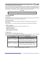
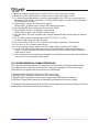
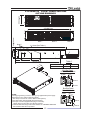
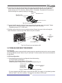
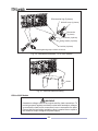
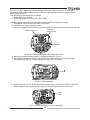
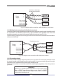
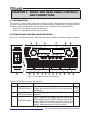
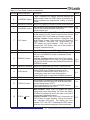
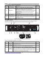
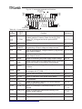
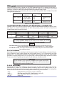
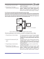
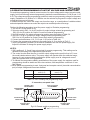
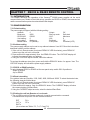
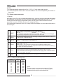
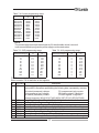
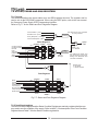
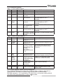
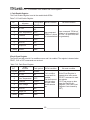
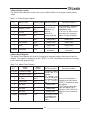
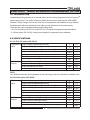
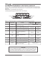
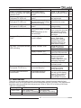
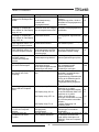
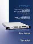
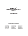
Table 4-1: Front Panel controls and indicators
Number Control/Indicator
Description
Green LED, lights when PREV button is pressed.
PREV indicator
15
16
Section
Voltage and Current Fine/Coarse adjustment control.
Operates as a toggle switch. In Fine mode, the
VOLTAGE and CURRENT encoders operate with high
resolution and in Coarse mode with lower resolution
(approx. 6 turns).
Auxiliary function: Advanced Parallel Operation
Mode setting.
Green LED, lights when the unit is in Fine mode.
Red LED, blinks in case of fault detection. OVP, OTP
Foldback, Enable and AC fail detection will cause the
ALARM LED to blink.
AC On/Off control.
FINE button
17
FINE indicator
18
ALARM indicator
19
AC Power switch
5.15.2
4.3 REAR PANEL
See Fig.4-2 to review the connections and controls located on the power supply rear panel.
Refer to Table 4-2 for explanations about the rear panel connections and controls.
9
10
8
J3
J2
SW1
J1
ON
OFF
OUT
AC INPUT
IN
150~600V
Models (shown)
7
6
5
4
3
2
8~10V Models
16~100V Models
1
Fig.4-2: Rear panel connections and controls
Table 4-2: Rear panel connections and controls
Number
1
2
3
Item
Description
Section
Header with a screw plug connector (Phoenix Contact
PC6-16/4-GF-10,16)
Bus-bars for 8V to 100V models.
DC output
Wire clamp connector for 150V to 600V models (shown).
RJ-45 type connector, use for connecting power supplies to
Remote-In RS232 or RS485 port of computer for remote control purposes.
connector When using several power supplies in a power system, the first
unit Remote-In is connected to the computer and the remaining
units are chained, Remote-In to Remote-Out.
AC input
connector
30
3.7
3.9.6
7.3
7.4