1
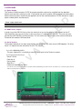
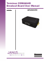
Terminus CDMA864D
Breakout Board User Manual
Issue: A00
ADVANCED
Bulletin
Revision
Date
JA06-BB-UM
A00
09 Dec 2010
TABLE OF CONTENTS
1 DISCLAIMER........................................................................................................................................................................ 2
2 INTRODUCTION................................................................................................................................................................... 3
3 GENERAL PURPOSE I/O..................................................................................................................................................... 3
4 INTERFACES..................................................................................................................................................................... 4-5
4.1 Power Supply............................................................................................................................................................. 4
4.2 UART Select Jumper................................................................................................................................................. 4
4.3 Serial Headers........................................................................................................................................................... 4
D
5 USB SERIAL PORTS............................................................................................................................................................ 5
5.1 Auxillary Port.............................................................................................................................................................. 5
5.1 1 Typical Port Settings
5.1 2 Diagnostics Interface
5.1.3 Port Settings
5.2 Telit GPS NMEA Port................................................................................................................................................. 5
5.2.1 Port Settings
C
E
6. GETTING STARTED.......................................................................................................................................................... 6-8
7. APPENDICES................................................................................................................................................................. 9-10
7.1 Approvals................................................................................................................................................................... 9
7.2 Safety......................................................................................................................................................................... 9
7.3 Abbreviations............................................................................................................................................................. 9
7.4 Ordering Information.................................................................................................................................................. 9
7.5 Revision History....................................................................................................................................................... 10
A
D
V
A
N
1 DISCLAIMER
The information contained in this document is the proprietary information of Connor-Winfield Corporation and its affiliates (Janus Remote Communication). The contents are confidential and any disclosure to persons other than the officers, employees, agents or subcontractors of the owner or licensee of this document, without the prior written consent of Connor-Winfield, is strictly prohibited.
Connor-Winfield makes every effort to insure the quality of the information it makes available. Notwithstanding the foregoing, Connor-Winfield does not make any warranty as to the information
contained herein, and does not accept any liability for any injury, loss or damage of any kind incurred by use of or reliance upon the information. Connor-Winfield disclaims any and all responsibility for
the application of the devices characterized in this document, and notes that the application of the device must comply with the safety standards of the applicable country, and where applicable, with
the relevant wiring rules. Connor-Winfield reserves the right to make modifications, additions and deletions to this document due to typographical errors, inaccurate information, or improvements to
programs and/or equipment at any time and without notice. Such changes will, nevertheless be incorporated into new editions of this application note.
All rights reserved 2010 Connor-Winfield Corporation
JA06-BB-UM Terminus Breakout Board User Guide - CDMA864D
Page 2
Rev: A00
Date: 12/09/10
© Copyright 2010 Janus Remote Communications All Rights Reserved Specifications subject to change without notice
2 INTRODUCTION
The following document describes the functions of the breakout board for the CDMA864D Terminus
module. This guide, along with the module’s user guide, allows all features of the terminal to be evaluated
and tested before reaching the field.
V
A
N
C
E
D
3 GENERAL PURPOSE I/O:
The breakout board for the CDMA864D exposes the following I/O via terminal block wire connection:
CMOS GPIO 1 through 7
ADC 1
UART SELECT
PWRMON
ON_OFF
RESET
VAUX I/O Reference Voltage
ENABLE
TRACE_RX
TRACE_TX
RS-232 TX
RS-232 RX
RS-232 RTS
RS-232 DTR
RS-232 DCD
RS-232 RING
RS-232 CTS
RS-232 DSR
A
D
Please refer to CDMA864D User Manual before making connection to any of these I/Os.
JA06-BB-UM Terminus Breakout Board User Guide - CDMA864D
Page 3
Rev: A00
Date: 12/09/10
© Copyright 2010 Janus Remote Communications All Rights Reserved Specifications subject to change without notice
4 INTERFACES
4.1 Power Supply
D
The Terminus module requires 12VDC for proper operation, and can be supplied from the breakout
board’s wire terminals or directly to the 2.1mm barrel jack on the module while plugged into the breakout
board. Note that power should only be applied in one of the mentioned places. Do not attempt to supply
power to both points simultaneously.
Power supply requirement
12Vdc ± 5%
10W peak
E
Voltage
Power
4.2 UART Select Jumper
C
In order to use the RS-232 lines on the wire terminals or to use the serial to USB adapter for the AT
Command Port, the user must place a shunt on across J1, labeled UART SELECT. The user may also
ground the UART SELECT terminal position. This will switch the RS-232 lines to the external interfaces
instead of the module’s DB9 connector.
N
4.3 Serial Headers
4.3.1 AT COMMAND PORT:
A
The breakout board has two right angle headers designed for FTDI serial to mini USB adapters. To utilize
these it is required to have the drivers for the FTDI chipset.
This port, labeled P6, is available to send AT commands to the Terminus module.
4.3.2 Typical Port Settings:
D
V
Baud: 115200
Data bits: 8
Parity: None
Stop Bits: 1
Hardware Handshaking: None
A
Note that since the serial to USB adapters only utilize TX/RX, handshaking is unused. However, the module’s use of RS-232 requires that the
RTS line externally must be grounded.
JA06-BB-UM Terminus Breakout Board User Guide - CDMA864D
Page 4
Rev: A00
Date: 12/09/10
© Copyright 2010 Janus Remote Communications All Rights Reserved Specifications subject to change without notice
4 INTERFACES continued
4.3.3 Trace Port
D
This port, labeled P5, is used for capturing debug data from the module. It can also be used for local
firmware upgrades of the cellular modules radio firmware.
Port Settings:
Baud: 115200
Data bits: 8
Parity: None
Stop Bits: 1
Hardware Handshaking: N/A
E
5 USB SERIAL PORTS:
C
The breakout board for the Terminus module has three serial ports available via the mini USB port, labeled
P14.To use this interface during development you will need to download the USB drivers from the Janus
website. It’s recommended to use this connection for development as it allows you multiple interfaces
with a single connection.
5.1 AUXILLARY PORT:
N
This port is available to send AT commands to module. Please refer to the CDMA864D Terminus User
Manual and Telit AT Command Guide for all available commands.
5.1.1 Typical Port Settings:
V
A
Baud: 115200
Data bits: 8
Parity: None
Stop Bits: 1
Hardware Handshaking: CTS/RTS
5.1.2 Diagnostics Interface
D
This port is used for debug and local firmware upgrades of the module’s radio firmware. Hardware
handshaking is not available on this port.
5.1.3 Port Settings:
A
Baud: 115200
Data bits: 8
Parity: None
Stop Bits: 1
Hardware Handshaking: N/A
5.2 TELIT GPS NMEA PORT:
This port is used to communicate with Telit’s integrated GPS hardware. Please refer to Telit AT
command guide for available settings and features to implement this port in your hardware design.
Hardware handshaking is not available on this port.
5.2.1 Port Settings:
Baud: 115200
Data bits: 8
Parity: None
Stop Bits: 1
Hardware Handshaking: N/A
JA06-BB-UM Terminus Breakout Board User Guide - CDMA864D
Page 5
Rev: A00
Date: 12/09/10
© Copyright 2010 Janus Remote Communications All Rights Reserved Specifications subject to change without notice
6 GETTING STARTED
Step 1
Please confirm that you have these items, and that your evaluation board is correctly set:
1 x Power supply with 2.1mm barrel connector termination
1 x 3’ Mini USB cable
D
Make sure that a shunt is placed on J1, or ENABLE BOARD UART.
E
Step 2
If not done already, plug the CDMA864D module into the 2x27 connector. To help with alignment, take note of the
silk screen outline and the holes that align with the Terminus’ mounting holes. Make sure the module is properly
aligned before continuing.
C
Step 3
Plug in your power supply to the 2.1mm barrel connector on the module. After roughly 2 seconds you should see
the STATUS LED on the module start blinking, this lets you know that the Terminus is powered and functioning.
D
V
A
N
Connect the mini USB cable to the mini USB port on the breakout board. Connect the other end to an available
USB port on your PC. In the computer’s device manager, you should see three (3) new ports become available.
A
You should see:
Telit Auxiliary Port
Telit Diagnostics Interface
Telit Nmea Port
If these do not become available, or you see an error message, this means you need to install the USB drivers for
the CDMA864D. Please refer to http://www.janus-rc.com/terminuscdma864d.html for the proper drivers before
continuing.
JA06-BB-UM Terminus Breakout Board User Guide - CDMA864D
Page 6
Rev: A00
Date: 12/09/10
© Copyright 2010 Janus Remote Communications All Rights Reserved Specifications subject to change without notice
6 GETTING STARTED continued
A
D
V
A
N
C
E
D
Step 4
Open HyperTerminal and start a new session. Use the drop down box to select the COM port that corresponds to
the Telit Auxiliary Port.
JA06-BB-UM Terminus Breakout Board User Guide - CDMA864D
Page 7
Rev: A00
Date: 12/09/10
© Copyright 2010 Janus Remote Communications All Rights Reserved Specifications subject to change without notice
6 GETTING STARTED continued
V
A
N
C
E
D
Then select “Configure.”, and select the following settings:
A
D
Bits per second: 115200
Data bits: 8
Parity: None
Stop bits: 1
Flow control: None
Then press “OK.”
Step 5
Click on the “Call” button in HyperTerminal to make the connection. In the window you should be able to send AT
commands. To make sure you have a proper connection, type “AT” into the window, and press Enter. You should
receive a response of “OK”.
If you do not receive that response, go back and check to make sure you’ve selected the correct COM port and
settings.
If you receive an OK, your connection is successful and you are now able to communicate with the module. The
CDMA864D User Manual gives step by step instructions on setting up voice and data calls, SMS messages, and
socket connections.
Please refer to http://www.janus-rc.com/terminuscdma864d.html for a link to additional Telit documentation,
including the AT Reference Guide; a full list of supported AT commands and their functions.
JA06-BB-UM Terminus Breakout Board User Guide - CDMA864D
Page 8
Rev: A00
Date: 12/09/10
© Copyright 2010 Janus Remote Communications All Rights Reserved Specifications subject to change without notice
7 APPENDICES
7.1 Approvals
7.1.1 Carrier Approval
7.1.1.1 Sprint
7.1.1.2 Verizon - Pending
7.1.2.1 FCC
7.1.2.2 CDG 1 and 2
E
D
7.1.2 Module Approval
7.2 Safety Recommendations (for Information only)
C
7.2.1 General
The Terminus CDMA864D terminal is based on the CDMA standard for cellular technology. This standard is
universal and covers Europe, Asia, United States and Africa which is the most used telecommunication standard.
N
7.2.2 Antenna Care and Replacement
Do not use the Terminus with a damaged antenna.
Buy the antenna from an approved suppliers list. Using unauthorized antennas, modifications, or attachments
could damage the Terminus and may violate local RF emission regulations or invalidate type approval.
Caution: DO NOT OVER-TIGHTEN ANTENNAS. Refer to Section 4.6.2.4 for torque specifications.
A
7.3 Abbreviations
ATerm
Definition
ADC
Analog-to-Digital Converter
CDMA
Micro Telephone or Handset (MT or HS)
PCM
Pulse Coded Modulation
Code Division Multiple Access
PDM
Pulse Density Modulation (in a DAC)
DAC
Digital-to-Analog Converter
RTC
Real Time Clock
EVRC
Enhanced Variable Rate CODEC
R-UIM
Removable User Identity Module
D
V
MT
General Purpose Input/Output
S-GPS
Simultaneous GPS
GPS
Global Positioning System
TGPIO
Telit General Purpose Input/Output
HF
Hands-Free
UART
Universal Asynchronous Receiver Transmitter
A
GPIO
I2C
Inter-Integrated Circuit
USB
Universal Serial Bus
JDR
Jammer Detector
VAUX
Voltage Auxiliary
JTAG
Joint Test Action Group (ANSI/ICEEE Std. 1149.1-1990)
ZIF
Zero Intermediate Frequency
7.4 Ordering Information
Ordering Information
Terminus Description
CDMA864D CDMA864D
V2.0 Sprint Certified
V3.0 Verizon Certified (pending)
JA06-BB-UM Terminus Breakout Board User Guide - CDMA864D
Page 9
Rev: A00
Date: 12/09/10
© Copyright 2010 Janus Remote Communications All Rights Reserved Specifications subject to change without notice
V
A
N
C
E
D
Terminus CDMA864D
Braekout Board User Manual
Revision
Revision Date
Note
12/17/10
Released Manual
A
A00
D
8.5 Revision History
Janus Remote Communications
Division of The Connor-Winfield Corporation
2111 Comprehensive Drive • Aurora, Illinois 60505
630.499.2121 • Fax: 630.851.5040
www.janus-rc.com