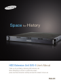
1
Space for History
HDD Extension Unit SVS-5 User’s Manual
Thank you for purchasing a Samsung HDD Extension unit.
Before attempting to connect or operate this product,
please read these instructions carefully and save this manual for future use.
ENGLISH
FCC Compliance Statement
Caution : Any changes or modification in construction of this device which are not
expressly approved the party responsible for compliance could void the user’s
authority to operate the equipment.
NOTE : This equipment has been tested and found to comply with the limits for a
Class A digital device, pursuant to part 15 of the FCC Rules. These limits are
designed to provide reasonable protection against harmful interference when the
equipment is operated in a commercial environment. This equipment generates,
uses, and can radiate radio frequency energy and, if not installed and used in
accordance with the instruction manual, may cause harmful interference to radio
Correct Disposal of This Product
(Waste Electrical & Electronic Equipment)
(Applicable in the European Union and other European countries
with separate collection systems) This marking shown on the
product or its literature, indicates that it should not be disposed with
other household wastes at the end of its working life. To prevent
possible harm to the environment or human health from
uncontrolled waste disposal, please separate this from other types
of wastes and recycle it responsibly to promote the sustainable
reuse of material resources. Household users should contact either
the retailer where they purchased this product, or their local
government office, for details of where and how they can take this
item for environmentally safe recycling. Business users should
contact their supplier and check the terms and conditions of the
purchase contract. This product should not be mixed with other
commercial wastes for disposal.
Samsung Techwin cares for the environment at all product
manufacturing stages to preserve the environment, and is
taking a number of steps to provide customers with more
environment-friendly products.The Eco mark represents
Samsung Techwin s will to create environment-friendly
products, and indicates that the product satisfies the EU
RoHS Directive.
This is a user manual for the SVS-5 HDD Extension Unit.
The manual will deal mainly with the external dimensions & parts of the
SVS-5 HDD Extension Unit, and how to connect it to the SAMSUNG
TECHWIN’s DVR system.
• SAMSUNG TECHWIN Co., LTD. All rights reserved. Under copyright law
this manual may not be copied, in whole or in part, without the consent of
SAMSUNG TECHWIN.
• The warranty is rendered invalid in cases where the product has been
abused or mishandled, where unauthorized repairs have been attempted
or performed, or deterioration of the product is due to normal wear and
tear. Please take notice of this warning.
*Caution
Samsung Techwin recommends the installation of a UPS
(Uninterrupted Power Supply) with all its recording products.
2
Notices
Resellers and users should keep in mind that this product has been
given EMC registration for business purposes.
• Don’t install in a humid, dirty, or dusty place.
• Don’t use in places exposed to extremes of temperature.
(Use where normal operation can be guaranteed)
• Avoid placing in direct sunlight or near heating appliances.
• Avoid places subject to vibration, or magnetic fields.
• Don’t put anything containing water (e.g. a vase or glass of water)
or anything heavy (e.g. a monitor) on top of the SVS-5 HDD
extension unit.
• Take care not to allow any objects that conduct electricity to be
inserted into the ventilation holes
• Don’t drop the product or subject it to shock.
(If an HDD is installed, the data can be damaged)
• Don’t modify or disassemble the product.
• When cleaning the product, don’t use water, but polish the surface lightly
with a dry cloth.
• If the device malfunctions, contact a dealer or service center immediately.
• This equipment is indoor use and all the communication wiring are limited
to inside of the building
*Caution
If the next articles are not followed, The fatal error can be made.
Remember it exactly!!!
1. When the DVR is connected to SVS-5, power off the DVR
certainly.
2. After power on the SVS-5, power on the DVR.
3. Don’t draw out the SATA Cable when the DVR is recording the
data to the SVS-5. ( When a power failure is happened in normal
functioning, the DVR works well with SVS-5 if power is supplied
again. )
3
Rack Mount Instruction
• If installed in a closed or multi-unit rack assembly, the operating ambient
temperature of the rack environment may be greater than room ambient.
Therefore, consideration should be given to installing the equipment in an
environment compatible with the maximum ambient temperature.
• Installation of the equipment in a rack should be such that the amount of
air flow required for safe operation of the equipment is not compromised.
• Mounting of the equipment in the rack should be such that a hazardous
condition is not achieved due to uneven mechanical loading.
• Consideration should be given to the connection of the equipment to the
supply circuit and the effect that overloading of the circuits might have on
overcurrent protection and supply wiring. Appropriate consideration of
equipment nameplate ratings should be used when addressing this concern.
• Reliable earthing of rack-mounted equipment should be maintained.
Particular attention should be given to supply connections other than direct
connections to the branch circuit.
4
Contents
1. Summary
5
1-1 Features
5
1-2 Contents
6
1-3 Parts
7
2. Installation
8
2-1 Method of HDD installation in SVS-5
8
2-2 Method of SATA board installation into DVR
11
2-2-1 Explanation of Composition
11
2-2-2 Method of Assemble and Disassemble
12
3. Connecting to the DVR
17
Appendix (Specifications)
20
5
1. Summary
1-1 Features
The SVS-5 HDD Extension Unit is a 19“ rack-mount type external
storage unit using an Serial ATA (SATA) interface, so that it can be
installed easily in a cabinet with a DVR (Digital Video Recorder). It
affords excellent space saving, because a maximum of 4 SATA HDDs
may be fitted to an 1U-height chassis.
• SVS-5S : SATA board exists / SVS-5E : SATA board doesn’t exist
(SATA board is Board Assy’ which expands one DVR to a max. of
4 SVS-5 HDD Extension Units and installed into the DVR.
- 11P Method of installation)
• 1U 19“ rack-mount type chassis
• SATA-to-SATA Port MultiPlier solution
• Max. 3.0Gbps transfer rate (SATA II) – capable of CIF 480fps
recording and playback
• Max. 4 SATA HDDs support
(up to a max. 2TB in case of using 500GB SATA HDD)
• Maximizes space saving and capacity relative to cost
• Easily expansible to a very large storage pool
6
1-2 Contents
You should find the following items in the package.
If anything is missing or broken, please inform your dealer
SVS-5 HDD Extension Unit chassis (1 EA)
SATA HDD carriers (4 EA)
SATA cable (1 EA)
AC power cable (1 EA)
User’s Manual (1 EA)
Spare Screws (1 Set)
SATA Board (Enclosed in SVS-5S)
7
1-3 Parts
Power/HDD LED
Ventilation holes
Handles
SVS-5 HDD Extension Unit (front)
Power Socket
Connection/Action LED
Cooling Fans
SATA PORT
Power Fan
SVS-5 HDD Extension Unit (rear)
8
Power Switch
2. Installation
2-1 Method of HDD installation in SVS-5
SVS-5 HDD Extension Unit can be equipped with a maximum of 4 SATA
HDDs. Please install the disks as follows.
※ Caution : HDDs suitable for use in the SVS-5 HDD Extension Unit are
Seagate (ST3250820AS 250GB, ST3500630AS 500GB). No compensation
will be made for problems resulting from use of other than the Seagate
(ST3250820AS 250GB, ST3500630AS 500GB). The warranty will be
invalidated by use of any other make of HDD.
The more HDD capacity is large, the longer the booting time of the DVR for
the confirmation of the HDD capacity.
1
Remove the screws from the top cover and push it back.
2
Prepare the enclosed SATA HDD carriers.
※Caution: There is no need to do the setting of Master/Slave in
case of SATA HDD.
9
3
Place the SATA HDD on the SATA HDD carrier and fix it tightly with
the screws. Use the HDD screws.
※Caution: The front and rear of the carrier are not the same.
Place the HDD in the center of the carrier.
4
Fix the SATA HDD carrier with its SATA HDD to the base and screw
it down with the pan head screws included. And connect the cable.
※Caution: Connect the cable tightly. Pay attention to the
direction of the cable.
10
④
③
②
①
②③
④
①
5
Connect SATA cables & power connectors to each SATA HDD.
※Caution: The controller SATA channel number should
correspond to the SATA HDD number as in the above picture.
6
Close the top cover and screw it down.
11
2-2 Method of SATA board installation into DVR
2-2-1 Explanation of composition
Install the SATA board into the DVR. Please install the SATA board as
follows.
SATA board ASS’Y
Section of SATA board ASS’Y
installation
Picture of the complete SATA board ASS’Y installation into the DVR
12
2-2-2 Method of Assemble and Disassemble
1
Remove the 13 screws marked in arrows and push it back
13
2
Raise up the connector lock on the DVR board before the SATA
board installation. (in the case where two fixing supporters are
mounted)
Top
Bottom
※ Reference
Be careful the direction of the flat cable by reference to the
above picture.
(The top side of the flat cable is blue color and the bottom side
of the flat cable has letters .)
14
3
Push the first flat cable into the connector as the blue section of it is
up on the board and put down the connector lock. The dotted line
printed on the flat cable must be parallel to the connector.
※Caution: Be careful the damage of the connector.
4
Push the second flat cable into the connector in the same way.
※Caution: If the flat cable is connected incorrectly, the DVR cannot
be booted.
15
사진 #8~9
5
Remove the cover of the both-faces tape on the back side of SATA
board
Screws
Adhesive side of
SATA board
6
Place the SATA board which fixing holes and fixing supporters on
the DVR are put in same line and screw it down. Press down bothfaces tape lightly to adhere SATA board closely to DVR.
16
B’
A’
A
B
7
Connect two flat cables to the SATA board with reference to 2, 3, 4.
※Caution: connect A to A‘ and B to B‘.
8
Close the top cover and screw it down.
17
3. Connecting to the DVR
The SVS-5 HDD Extension Unit is connected to the SATA port on the
DVR system. Please set up the overall system as follows.
※ Application : SVR-1650E / 1640E / 950E
SATA PORT
1
Check the SATA port at the back of the SVS-5 HDD Extension Unit.
DVR(SVR-950)
SVS-5
SATA Cable
DVR(SVR-1650/1640)
SVS-5
SATA Cable
2
Connect the SATA PORT of SVS-5 HDD Extension Unit to the
DVR’s SATA port, using an SATA cable as above.
※ Use the enclosed SATA cable.
18
3
Power up using the switch at the rear.
※Caution: Note the order of action of the power source
① power-on : SVS-5 → DVR
② power-off : DVR → SVS-5
LINK LED
ACT LED
SATA PORT
4
After power on, check out the LINK LED and the ACT LED at the
rear of the SVS-5 HDD Extension Unit are lighted in order. The
LINK LED is lighted when the SVS-5 HDD Extension Unit is
connected to the DVR in order. The ACT LED is lighted when the
data are read and written to the SVS-5 HDD Extension Unit.
19
*Be careful the direction of the SATA cable when use it.
Connecting the DVR with SATA cable
Connecting SVS-5 with SATA cable
Connecting the SATA cable which
letters must be bottom side
Connecting the SATA cable which
letters must be top side
20
5
Ascertain that 4 LEDs at the front panel are lighted on in order after
power on the SVS-5.
: The blue LED is lighted on when the power is supplied to the
SVS-5
1 : Indicate the state of SATA HDD 1
2 : Indicate the state of SATA HDD 2
3 : Indicate the state of SATA HDD 3
4 : Indicate the state of SATA HDD 4
① Green LED is lighted : When a SATA HDD is mounted.
② RED LED is lighted : When a SATA is used.
③ Green LED and Red LED blink : Error
21
*Explanation the order of HDDs recognized in DVR
-“The order of HDDs recognized in DVR is decided by the
order of connection in the SVS-5.
22
DVR
SVS-5 (4)
SVS-5 (3)
SVS-5 (2)
SVS-5 (1)
SATA Cable
6
There are 4 SATA ports at the DVR. So, It is possible to expand one
DVR to a max. of 4 SVS-5 HDD Extension Units. (The order of
recording is decided by the order of SATA port at the DVR.)
① Before power on the SVS-5, Check out the power off
of the DVR.
② After power off the DVR, power off the SVS-5.
* If the order of action of the power source is not
followed, The fatal error can be made.
23
Specifications
Host Connectivity
One external SATA PORT (for DVR connection)
Max. 3.0Gbps transfer rate (SATA II)
Maximum cable length : 2.0m
Disk Connectivity
Max. 4 SATA HDDs support
Compliant with SATA-2 standard
Dimensions (approximate)
Width(W) × Height(H) × Depth(D) : 48.4cm×4.4cm×45.0cm
Weight (without HDD)
: 5.6kg
Power
AC 115V~230V (50 / 60Hz) Max. 2A
Operating Environment
Operating Temperature
Relative Humidity
:
:
24
5℃ ~ 45℃
20% ~ 70% (non-condensing)
SALES NETWORK
•
SAMSUNG TECHWIN CO., LTD.
333-1, Sangdaewon 1-dong, Jungwon-gu, Seongnam-si,
Gyeonggi-do 462-807, Korea
TEL : +82-31-730-8931~3 FAX : +82-31-730-8950
•
SAMSUNG OPTO-ELECTRONICS UK, LTD.
Samsung House, 1000 Hillswood Drive, Hillswood Business
Park Chertsey, Surrey KT16 OPS
TEL : +44-1932-45-5308 FAX : +44-1932-45-5325
www.samsungtechwin.com
www.samsungcctv.com
•
TIANJIN SAMSUNG OPTO-ELECTRONICS CO., LTD.
7 Pingchang Rd, Nankai Dist. Tianjin 300190, P.R China
TEL : +86-22-2761-4724(33821) FAX : +86-22-2761-6514