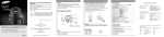
1
Perfect Control Solution
Video Matrix Switcher SMX-25632 User’s Manual
SALES NETWORK
•
SAMSUNG TECHWIN CO., LTD.
145-3, Sangdaewon 1-dong, Jungwon-gu, Seongnam-si,
Gyeonggi-do 462-703, Korea
TEL : +82-31-740-8137~8139 FAX : +82-31-740-8145
•
SAMSUNG OPTO-ELECTRONICS UK, LTD.
Samsung House, 1000 Hillswood Drive, Hillswood Business
Park Chertsey, Surrey KT16 OPS
TEL : +44-1932-45-5308 FAX : +44-1932-45-5325
www.samsungtechwin.com
www.samsungcctv.com
•
TIANJIN SAMSUNG OPTO-ELECTRONICS CO., LTD.
7 Pingchang Rd, Nankai Dist. Tianjin 300190, P.R China
TEL : +86-22-2761-4724(33821) FAX : +86-22-2761-6514
Thank you for purchasing a Samsung Video Matrix Switcher.
Before attempting to connect or operate this product,
please read these instructions carefully and save this manual for future use.
P/No. : Z6806-0766-01A
VAN 06. 06
ENGLISH
Safety caution
Caution
Warning
• All work related to the installation of this appliance must be performed by qualified
service personnel or system installers.
- If the product is connected or installed improperly, electric shock, fire, severe injury, and/or
damage can result.
• Please install the product on a completely flat floor.
- Always check the strength and stability of the installation location.
- Do not drop the appliance on the floor. This may result in damage or injury.
Do not attempt to disassemble the appliance. To prevent electric shock, do not remove
screws or covers.
- There are no user-serviceable parts inside. Contact qualified service personnel for
maintenance.
• Never use the appliance in places where there are flammable materials.
- Never use the appliance in places where flammable materials such as gas are used.
• This may result in fire, explosion, and other serious accidents.
• Never touch un-insulated parts with wet hands.
- Touching un-insulated parts with wet hands may result in serious electric shock.
• Never expose the appliance to water or moisture.
- If the appliance gets wet, immediately turn the power off.
- Stop using the appliance if it gets wet. Contact the manufacturer immediately.
• Stop using the appliance if there appears to be any operational problem.
- Immediately turn the power off to the appliance if there is any abnormal condition such as
smoke or unusual smells.
- Continuing to use the appliance under abnormal conditions may result in serious damage.
• Always use the recommended power.
- Using incorrect power source ratings may result in fire, electric shock, or damage.
• Always handle the connection cable with care.
- Never damage or modify the connection cable.
- Do not pull, expose to heat, or place heavy objects on the connection cable.
- Non-observance of these warnings may result in fire, electric shock or damage.
• Use the appliance indoors only.
- Do not place the appliance outdoors or expose it to rain or moisture.
- If dropped in water, the appliance may be corroded and damaged.
• Do not use the appliance where there is excessive dust, smoke, or moisture.
- Using the appliance under such conditions may result in fire, electric shock or serious
damage.
• Do not operate the appliance in temperatures beyond those specified.
- Excessive heat or cold may damage the appliance.
- Always operate the appliance within the recommended temperature range of 0˚C ~ 40˚C.
• Do not place the appliance in direct sunlight.
- This may discolor the appliance.
• Do not apply excessive shock to the appliance.
- Excessive shock may damage the appliance.
Maintenance and Repair
If the controller body gets dirty, turn the power off and wipe the surface with a soft cloth.
- Do not use chemical agents such as alcohol or benzene. For detailed information on
upgrading the firmware, please direct your inquiries to the installation vendor.
Refer all work related to the installation of this appliance to qualified service personnel or
system installers.
For U.S.A
This equipment has been tested and found to comply with the limits for a Class A digital device, pursuant to Part 15
of the FCC Rules. These limits are designed to provide reasonable protection against harmful interference when the
equipment is operated in a commercialenvironment. This equipment generates, uses, and can radiate radio frequency
energy and, if not installed and used in accordance with the instruction manual, may cause harmful interference to
radio communications. Operation of this equipment in a residential area is likely to cause harmful interference, in
which case the user will be required to correct the interference at his own expense.
Avoid locations near power lines or where high frequency is used.
Placing the product near electromagnetic wave generating communication equipments or
transmission lines may cause the product to malfunction.
VIDEO METRIX SWITCHER
2
User’s Manual
VIDEO METRIX SWITCHER
3
User’s Manual
Contents
2
Safety caution
12
12
13
13
13
3. AUTO SELECT
3-1. AUTO SELECT Setup
6
Features & Distinctions
3-2. AUTO SELECT Cancellation
3-3. AUTO SELECT Elimination
Features
3-4. AUTO SELECT RUN/HOLD FUNCTION
7
System Diagram
1. System Connection Diagram
2-3. Extension Matrix
7
7
8
9
9
10
10
2-4. Setting the SMX-25632 DIP Switch
11
1-1. Front
1-2. Back
2. Basic Connection Diagram
2-1. Matrix System
2-2. Matrix Cable
Matrix Settings
12
1. Selection of camera and monitor
12
12
2. Joystick for Camera Controls
VIDEO METRIX SWITCHER
4
User’s Manual
4. ID SET
14
14
14
15
15
15
16
16
4-1. ID SET Setup
4-2. ID SET ON/OFF Setup1
4-3. DISPLAY POSITION Setup
5. TIME/DATE SET
5-1. TIME/DATE Setup
5-2. ON/OFF Setup
5-3. DISPLAY POSITION Setup
Check List
17
External View
18
MATRIX Features
19
VIDEO METRIX SWITCHER
5
User’s Manual
Features & Distinctions
Features
System Diagram
1. System Connection Diagram
1-1. Front
Input/Output
• 1 video card (SMV-25632) handles signals from 64 cameras & 2 monitors
• Up to 16 video cards (SMV-25632) may be inserted into the main CPU (SMX-25632)
to handle up to 32 monitors
OSD Output
• Supports 16 Korean characters or 32 alphabet letters
• Built-in I/D, time, and generator function for each video card (SMV-25632)
• Features prevention for screen-shakes caused by changes in sync signal when
switching between manual and auto camera
CPU Extension
• Extension set (SME-25632) - 1 extension unit: controls 128 cameras & 32 monitors
2 extension unit: controls 192 cameras & 32 monitors
3 extension unit: controls 256 cameras & 32 monitors
System Distinctions
• Easy to insert/remove, manage, maintain, or extend video cards
Power Unit
• Built-in power unit for safer power supply
VIDEO METRIX SWITCHER
6
User’s Manual
MAIN POWER
Turns the power of the device on/off
STATUS
Displays the operating status of the device
ETHERNET SLOT
Caution
• This is an ETHERNET SLOT( ) : do not insert a video card (SMV-25632).
• When inserting a video card (SMV-25632), pay attention to the direction and the
location so as to insert it properly.
• Video card slot
* Start from the left; insert the card so
that it is facing the left, and push until
it makes a “clicking sound.”
No. inserted No. of Cameras & Monitors Controlled
64 cameras & 2 monitors
1
64 cameras & 4 monitors
2
64 cameras & 6 monitors
3
16
VIDEO METRIX SWITCHER
7
64 cameras & 32 monitors
User’s Manual
System Diagram
1-2. Back
2. Basic Connection Diagram
2-1. Matrix System
CAMERA INPUT
: CH1~CH64
MONITOR OUTPUT: CH1~CH32
EXTENSION INPUT : Connect the extension unit (SME-25632)
AC INPUT
Select a power voltage (100~120V, 210~230V)
ETHERNET
Connect to a computer (control through a network) : To be applied in the future.
KEYBOARD
System controller (SCC-3100) connection control
Caution
• Use the connector included with the unit when connecting an extension unit
(SME-25632) to the main CPU.
VIDEO METRIX SWITCHER
8
User’s Manual
VIDEO METRIX SWITCHER
9
User’s Manual
System Diagram
• Extention I/O Port
2-2. Matrix Cable
Connection cables are within the matrix; cables may vary slightly.
Matrix Keyboard Port
SCC-3100 PORT 3 Connection Terminal
• When using a matrix extension unit (SME-25632), set the inner DIP switch.
2-3. Matrix Extension Unit
Diagram of Matrix main CPU(SMX-25632) & its extension units’(SME-25632) proper
connection.
When the Address is set to 1(ON) sets camera no.65 to 128
When the Address is set to 2(ON) sets camera no.129 to 192
When the Address is set to 3(ON) sets camera no.193 to 256
* To turn address number 3 on, turn both numbers 1 and 2 on at the same time.
SMX-25632
(Main CPU)
2-4. Setting the SMX-25632 DIP Switch
SME-25632
Extension Unit
• The default DIP switch setting is the appropriate setting for the
country the SMX-25632 is sold in.
• See below chart for the OSD and NTSC/PAL mode settings.
• Remove the front cover before setting the switches.
SME-25632
Extension Unit
SME-25632
Extension Unit
SMX-25632(dip switch)
• A twisted pair cable must be used for RS -422 or RS -485 data transmission operation.
• Place extension units(SME-25632) under the Matrix Main CPU(SMX-25632).
VIDEO METRIX SWITCHER
10 User’s Manual
DIP No.
1
2
3
4
ON
OSD, Korean
NTSC
-
VIDEO METRIX SWITCHER
OFF
OSD, English
PAL
-
11 User’s Manual
Detail
Select OSD
Select Imaging Mode
-
Matrix Settings
Connect the system controller(SCC-3100) before setting the matrix.
1. Selection of Camera and Monitor
Select a number between 1 and 255, and then press
the CAMERA button to select the corresponding
camera.
AUTO SELECT SET
CAM ID:1
MONITOR:12
[ --- ]
Camera: Camera select
Select a number between 1 and 60, and then press
the ENTER button to select the corresponding HOLD
TIME.
AUTO SELECT SET
CAM ID:12 Time: __
MONITOR:12
[ --- ]
Enter: Hold time set
This is a manual function to display the cameras connected to the MATRIX SYSTEM on the monitor.
Select Monitor : Select a monitor number between 1 and 32. Press ENTER.
Select Camera : Select a camera number between 1 and 255. Press CAMERA.
• Monitor must be selected before the camera. Default is 1, and up to 255 cameras can be
selected by connecting up to 3 input MATRIX extensions.
3-2 Cancel AUTO SELECT
2. Joystick for Basic Camera Controls
This is a function to cancel AUTO RUN
JOYSTICK : Used for moving the PAN/TILT up/down/left/right/diagonal.
ZOOM
: Use the TELE button for Telephoto view
(Turn the TELE button or the Joystick clockwise for Telephoto view)
Use the WIDE button for WIDE view
(turn the WIDE button or the Joystick counterclockwise for WIDE view)
FOCUS : + button to focus away
- button to focus closer
Press the MENU button, and then press the 1 button.
(In MATRIX, wait for data loading completion.)
Press the ESC or the SET button to exit the
corresponding setting.
MATRIX CONTROL
CAM ID:12
DRX
MONITOR:12
[ --- ]
MASTER ID:1
3-3. Delete AUTO SELECT
This is a function to delete each AUTO RUN setting.
3. AUTO SELECT
3-1. AUTO SELECT Setup
This is a function to select cameras to be displayed on the monitor in AUTO RUN.
From the initial screen, press the MONITOR button
and then press the MENU button to display the
[MATRIX CONTROL] menu.
Press button 1 to display the [AUTO SELECT SET]
menu. (In MATRIX, wait for data loading completion.)
Select a number between 1 and 32, and then press the
ENTER button to select the corresponding monitor.
VIDEO METRIX SWITCHER
12 User’s Manual
MATRIX CONTROL
1:AUTOSELECT 2:CLEAR
3:ID SET
4:TIME SET
Press Numeric Key
AUTO SELECT SET
MONITOR:1
[ --- ]
Enter: Monitor select
Press the MENU button, and then press button 2.
Select a number between 1 and 32, and then press
the ENTER button to select the monitor to be
canceled.
AUTO SELECT CLEAR
MONITOR:12
[ --- ]
Enter: All clear
3-4. AUTO SELECT RUN/HOLD
Press the AUX2 button to RUN all MATRIX channels.
Press the AUX3 button to HOLD all MATRIX channels.
Select a number between 1 and 32, and then press the AUX2 button to RUN the
corresponding MATRIX channel.
Select a number between 1 and 32, and then press the AUX3 button to HOLD the
corresponding MATRIX channel.
VIDEO METRIX SWITCHER
13 User’s Manual
Matrix Settings
4-3. Setting the DISPLAY POSITION
4. ID SET
This is a function to enter text on the corresponding
camera.
<I/D SET>
1. ID CHANGE SET
2. I/D ON/OFF
3. DISPLAY POSITION
4-1 Select ID SET
From the initial screen, press the MONITOR button,
<I/D SET>
and then press the MENU button to display the
[MATRIX CONTROL] menu.
CAMERA ____________________
Press button 3 to display the [CAMERA ID SET] menu.
(In MATRIX, wait for data loading completion.)
Move the joystick to select the ID CHANGE SET from the
MATRIX screen, and then press the “FOCUS +“ button.
Move the joystick up/down to change letters or
numbers, use the joystick's ZOOM to change letters/numbers/vowels/consonants.
Press the “FOCUS +“ button to save.
From the initial screen, press the MONITOR button,
and then press the MENU button to display the
[MATRIX CONTROL] menu.
Press the 3 button to display the [CAMERA ID SET]
menu. (In MATRIX, wait for data loading completion.)
Move the joystick to select the DISPLAY POSITION
from the MATRIX screen, and then press the “FOCUS
+“button.
Move the joystick up/down/left/right to move the ID location.
Press the “FOCUS +“button to save.
5. TIME/DATE SET
Move Position with a Joystick
Press ENTER, SAVE
CAMERA:001
<TIME/DATE SET>
This is a function to modify the TIME and DATE on
the corresponding camera.
1. TIME / DATE SET
2. TIME / DATE ON/OFF
3. DISPLAY POSITION
5-1. Setting TIME/DATE
4-2. Setting ID SET ON/OFF
From the initial screen, press the MONITOR button,
and then press the MENU button to display the
[MATRIX CONTROL] menu.
Press the 3 button to display the [CAMERA ID SET]
menu. (In MATRIX, wait for data loading completion.)
Move the joystick to select the DISPLAY POSITION from the
MATRIX screen, and then press the “FOCUS +“button.
Move the joystick up/down to select a monitor, move
it left/right to select ON/OFF.
Press the “FOCUS +“button to save.
VIDEO METRIX SWITCHER
14 User’s Manual
MONITOR:01[ON]
From the initial screen, press the MONITOR button,
<TIME/DATE SET>
and then press the MENU button to display the
[MATRIX CONTROL] menu.
2003/10/10 08:00:00 SAVE?
Press the 4 button to display the [TIME SET] menu. (In
MATRIX, wait for data loading completion.)
Move the joystick to select the TIME/DATE SET from the
MATRIX screen, and then press the “FOCUS +“button.
Move the joystick up/down to change the TIME or
DATE, move it left/right to move the location.
Move the joystick to select the “SAVE?” and wait for it to blink, and then press the
“FOCUS +“ button to save.
VIDEO METRIX SWITCHER
15 User’s Manual
Check List
Matrix Settings
5-2. Setting ON/OFF
No power.
Is power supply normal?
Reconnect after checking the
power supply.
Power is on but nothing is
happening.
Is keyboard connection normal?
Check the keyboard connection.
Cameras are not displayed
in order on the monitor.
Do camera inputs on the back
match the actual camera
numbers?
Check the camera inputs on the
back against the actual camera
numbers.
Cameras cannot be
displayed on a certain
monitor.
Is Video card (SMV-25632)
inserted properly into the
corresponding slot?
Check if the video card is inserted;
with a little force, push the video
card once more.
Is connector securely
connected to the monitor in
question?
Check the connector connection;
check the power on VCR/monitor.
None of the monitors display
the camera in question?
Check the connection between the
camera in question and the main
CPU; check the power on the
camera.
Only certain monitors do not
display the camera?
Carefully reinsert the video card
into the corresponding monitor.
Is data line connected properly?
(+, - )
Check the polarity and the
connection of the data line.
Do camera numbers in the
controller match the R/X
numbers?
Reassign the R/X or the controller
numbers.
5-3. Setting DISPLAY POSITION
From the initial screen, press the MONITOR button,
and then press the MENU button to display the
Move Position with a Joystick
Press ENTER, SAVE
[MATRIX CONTROL] menu.
Press the 4 button to display the [TIME SET] menu. (In
2006/10/10/08:00:00
MATRIX, wait for data loading completion.)
Move the joystick to select the DISPLAY POSITION
from the MATRIX screen, and then press the “FOCUS
+“ button.
Move the joystick up/down/left/right to move the display position.
Press the “FOCUS +“ button to save.
Caution
• ERROR may occur if operated before data is fully loaded.
Perform
Check if….
Symptom
From the initial screen, press the MONITOR button,
and then press the MENU button to display the
[MATRIX CONTROL] menu.
MONITOR:01[ON]
Press the 4 button to display the [TIME SET] menu. (In
MATRIX, wait for data loading completion.)
Move the joystick to select the TIME/DATE ON/OFF
from the MATRIX screen, and then press the “FOCUS
+“ button.
Move the joystick up/down to select a monitor, move it left/right to select ON/OFF.
Press the “FOCUS +“ button to save.
One of the connected
cameras cannot be
displayed.
Pan/Tilt functions are not
working.
* You must turn the power off when inserting/removing a card into/from this device.
VIDEO METRIX SWITCHER
16 User’s Manual
VIDEO METRIX SWITCHER
17 User’s Manual
MATRIX Features
External View
SMX-25632
ITEM
SME-25632
Camera I/O
Communication
Operating Environment
Weight
Size
MATRIX Main CPU (SMX-25632)
16 video card slots
controller interface
256 x 32 video matrix control
video extension unit connector (up to 3 sets)
shake prevention when switching screens
displays 16 Korean characters or 32 alphabet letters, numbers, or symbols
date/time display
64 camera input, 32 monitor output
TTL LEVEL
0˚C ~ +40˚C (32˚F ~ 104˚F)
Approx. 15kg (approx. 33lb)
430(W) x 265(H) x 350(D)mm (approx. 17x10x14in)
ITEM
Features
Camera I/O
Power Wattage
Operating Temperature
Weight
Size
Video MATRIX extension unit (SME-25632)
64 camera input control
64 input channels, 32 extension output channels
50 watts
0˚C~+40˚C (32˚F ~ 104˚F)
Approx. 10Kg (approx. 22lb)
430(W)X177(H)X350(D)mm
System
Features
OSD
350
350
177
265
ITEM
430
Features
430
OSD
SMV-25632
Camera I/O
Power Wattage
Operating Temperature
Weight
187
Video Card (SMV-25632)
time generator
I/D generator
video I/O selector
video sync correction
32 alphabet letters or 16 Korean characters (combinations allowed)
freeze On/Off
year, month, date, hour, minute, second
64 input, 2 monitor output
max. 9 watts
0˚C ~ +40˚C (32˚F ~ 104˚F)
Approx. 0.3Kg (approx. 10oz)
* Standards may change without prior notice in order to improve performance/quality of the product.
293.7
VIDEO METRIX SWITCHER
18 User’s Manual
VIDEO METRIX SWITCHER
19 User’s Manual