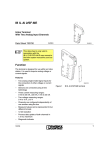
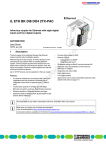
1
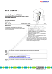
IB IL TEMP 2 UTH (-PAC)
D
2U
Inline Terminal With 2 Analog Input Channels for
Thermocouple Connection
TH
Data Sheet
5722_en_03
© PHOENIX CONTACT - 10/2007
Description
–
–
–
2 differential inputs for thermocouples or linear voltage;
1 input for an external Pt1000 or Ni1000 cold junction.
Configuration of channels via the bus system
Internal detection of cold junction temperature
(configurable)
Absolute or differential temperature measurement
(configurable)
Pt1000 sensor in the vicinity of the connection terminals
of the thermocouple inputs for internal measurement of
the cold junction temperature
Measured values can be represented in 3 different
formats
Approved for the use in potentially explosive areas
(observe the notes on page 7)
s.
–
ne
The terminal is designed for use within an Inline station.
Signals of standard thermocouples can be detected using
this terminal.
13 different types of thermocouples are supported in
accordance with DIN EN 60584-1 and DIN 43710 as well
as a linear voltage input of -15 mV up to +85 mV.
co
Features
nt
1
m
AUTOMATIONWORX
po
–
–
on
l
in
ec
om
–
This data sheet is only valid in association with the IL SYS INST UM E user manual or the Inline system manual
for your bus system.
Make sure you always use the latest documentation.
It can be downloaded at www.download.phoenixcontact.com.
A conversion table is available on the Internet at
www.download.phoenixcontact.com/general/7000_en_00.pdf.
This data sheet is valid for the following products listed under "Ordering Data" on page 3.
IB IL TEMP 2 UTH (-PAC)
Table of Contents
1
Description.................................................................................................................................. 1
2
Ordering Data ............................................................................................................................. 3
3
Technical Data............................................................................................................................ 4
4
Local Diagnostic Indicators and Terminal Point Assignment...................................................... 6
4.1
4.2
4.3
Local Diagnostic Indicator .............................................................................................................................. 6
Function Identification .................................................................................................................................... 6
Terminal Point Assignment ............................................................................................................................ 6
Installation Instructions ............................................................................................................... 6
6
Notes on Using the Terminal in Potentially Explosive Areas...................................................... 7
7
Internal Circuit Diagram.............................................................................................................. 8
8
Electrical Isolation....................................................................................................................... 8
9
Connection Notes ....................................................................................................................... 9
nt
s.
co
m
5
10 Connection Examples .......................................................................................................................................... 9
ne
Absolute Temperature Measurement............................................................................................................. 9
Differential Temperature Measurement ....................................................................................................... 10
Equalizing Conductor Extension .................................................................................................................. 10
po
10.1
10.2
10.3
11 Programming Data/Configuration Data .....................................................................................11
Output Data For Configuration of the Terminal (See page 12) .................................................................. 11
Assignment of the Terminal Points to the Input Data (See page 14) ......................................................... 11
Process Data Output Words (OUT) ............................................................................................................. 12
Process Data Input Words (IN) .................................................................................................................... 14
in
ec
12.1
12.2
12.3
12.4
om
12 Process Data .............................................................................................................................11
13 Formats for the Representation of Measured Values................................................................15
Format 1: IB Standard.................................................................................................................................. 15
Format 2....................................................................................................................................................... 16
Format 3....................................................................................................................................................... 17
on
l
13.1
13.2
13.3
14 Measuring Ranges ....................................................................................................................18
14.1
14.2
14.3
Measuring Range Depending on the Resolution (Format 1 (IB Standard) and Format 3)........................... 18
Measuring Ranges Depending on the Resolution (Format 2)...................................................................... 18
Input Measuring Values ............................................................................................................................... 19
15 Tolerance and Temperature Response.....................................................................................20
15.1
15.2
15.3
15.4
15.5
15.6
15.7
5722_en_03
Tolerances at an Ambient Temperature TA = +25°C ................................................................................... 20
Tolerances at an Ambient Temperature TA = -25°C up to +55°C ................................................................ 21
Temperature Behavior ................................................................................................................................. 22
Tolerances of the Internal Cold Junction...................................................................................................... 22
Tolerances Due to Linearization .................................................................................................................. 23
Additional Tolerances When Subject to EMI .............................................................................................. 24
Process Data Update Time .......................................................................................................................... 24
PHOENIX CONTACT
2
IB IL TEMP 2 UTH (-PAC)
2
Ordering Data
Products
Description
Type
Order No.
Pcs./Pkt.
Inline terminal with 2 analog input channels for temperature measurement;
complete with accessories (connector with labeling field)
IB IL TEMP 2 UTH-PAC
2861386
1
Inline terminal with 2 analog input channels for temperature measurement;
without accessories
IB IL TEMP 2 UTH
2727763
1
The connector listed below is needed for the complete fitting of the IB IL TEMP 2 UTH terminal.
Type
Inline shield connector for analog Inline terminals
IB IL SCN-6 SHIELD TWIN
2740245
Thermoelectric voltage terminal block pair for CU/CUNI44
copper/constantan
MTKD-CU/CUNI
3100059
Thermoelectric voltage terminal block pair for FE/CUNI44
iron-constantan
MTKD-FE/CUNI
Thermoelectric voltage terminal block pair for NICR/CUNI44
nichrome-constantan
MTKD-NICR/CUNI
3100075
Thermoelectric voltage terminal block pair for NICR/NI
nichrome-nickel
MTKD-NICR/NI
3100062
MTKD-E-CU/A-CU
3100091
m
Accessories
Description
ne
om
Documentation
Description
po
Thermoelectric voltage terminal block pair for E-CU/A-CU
copper/cupro-nickel
Thermoelectric voltage terminal block pair for S-CU/E-CU
S-copper/copper
nt
s.
Thermoelectric voltage terminal block pair for equalizing conductor extension
co
Order No.
5
3100046
MTKD-S-CU/E-CU
3100101
Type
Order No.
"Automation Terminals of the Inline Product Range" user manual
IL SYS INST UM E
2698737
"Configuring and Installing the INTERBUS Inline Product Range"
user manual
IB IL SYS PRO UM E
2743048
in
ec
Pcs./Pkt.
Pcs./Pkt.
1
DB GB IBS SYS ADDRESS
9000990
1
AH EN IL EX ZONE 2
7217
1
on
l
"INTERBUS Addressing" data sheet
"Inline Terminals for Use in Zone 2 Potentially Explosive Areas"
application note
5722_en_03
PHOENIX CONTACT
3
IB IL TEMP 2 UTH (-PAC)
3
Technical Data
General Data
Housing dimensions (width x height x depth)
12.2 mm x 120 mm x 71.5 mm
Weight
46 g (without connector) / 67 g (with connector)
Operating mode
Process data mode with 2 words
Transmission speed
500 kbps
Connection method for sensors
2-wire technology
Ambient temperature (operation)
-25°C to +55°C
Ambient temperature (storage/transport)
-25°C to +85°C
Permissible humidity (operation/storage/transport)
10% to 95% according to DIN EN 61131-2
70 kPa to 106 kPa (up to 3000 m above sea level)
Degree of protection
IP20 according to IEC 60529
Class of protection
Class 3 according to EN 61131-2, IEC 61131-2
m
Permissible air pressure (operation/storage/transport)
Connection data for Inline connectors
Spring-cage terminals
Conductor cross-section
0.2 mm2 to 1.5 mm2 (solid or stranded), 24 - 16 AWG
s.
Interface
co
Connection type
Through data routing
nt
Local bus
Supply of the Module Electronics and I/O Through Bus Coupler/Power Terminal
Potential routing
ne
Connection method
Power Consumption
7.5 V
po
Communications power UL
Current consumption at UL
43 mA (typical)
24 V DC
Analog supply voltage UANA
11 mA (typical)
om
Current consumption at UANA
Total power consumption
Number
Connection of the signals
Cable length
in
ec
Analog Inputs
590 mW (typical)
2 inputs for thermocouples or linear voltage
2-wire, shielded equalizing conductor for TC with encapsulated sensors
Shorter than 30 m for shielded cables
Sensor types that can be used
B, C, E, J, K, L, N, R, S, T, U, W, HK
Characteristics standards
DIN EN 60584-1: 1995 (B, E, J, K, N, R, S, T)
DIN 43710 (U, L)
on
l
Voltage input range
-15 mV up to +85 mV
Termperature measuring unit
Either Celsius, Fahrenheit or µV scale
Temperature measuring range
See Table on page 19
Resolution in the process data word (quantization)
Configurable, see Tableon page 13
Resolution of measuring values
See Table page 18
Measured value representation
In the formats
Format 1 (IB standard)
Format 2
Format 3
Conversion procedure of the analog/digital converter
(15 bits with sign bit)
(12 bits with sign bit)
(15 bits with sign bit)
Successive approximation
Conversion time of the analog/digital converter
120 µs, typical
Process data update
30 ms, maximum, for both channels
Limit frequency of the analog filter
48 Hz
Safety Equipment
Surge proof up to ±40 V
5722_en_03
TC channels: Connections 1.2 and 2.2 as well as 1.3. and 2.3
PHOENIX CONTACT
4
IB IL TEMP 2 UTH (-PAC)
Electrical Isolation/Isolation of the Voltage Areas
Common Potentials
24 V main voltage UM, 24 V segment voltage US, and GND have the same potential. FE is a separate potential area.
Separate Potentials in the System Consisting of Bus Terminal Module/Power Terminal and Analog I/O Terminal
Test Distance
Test Voltage
5 V supply incoming remote bus/7.5 V supply (bus logic)
500 V AC, 50 Hz, 1 min
5 V supply outgoing remote bus/7.5 V supply (bus logic)
500 V AC, 50 Hz, 1 min
7.5 V supply (bus logic) / 24 V supply (I/O)
500 V AC, 50 Hz, 1 min
7.5 V supply (bus logic) / 24 V analog supply (analog I/O)
500 V AC, 50 Hz, 1 min
500 V AC, 50 Hz, 1 min
24 V analog supply (analog I/O) / functional earth ground
500 V AC, 50 Hz, 1 min
m
24 V supply (I/O) / functional earth ground
Error Messages to the Higher-Level Control or Computer System
Yes
Failure of or insufficient communications power UL
Yes, I/O error message sent to the bus terminal
Peripheral fault/user error
Yes, error message via the process data input words (see page 14)
s.
co
Failure of the internal voltage supply
Approvals
on
l
in
ec
om
po
ne
nt
For the latest approvals, please visit www.download.phoenixcontact.com or www.eshop.phoenixcontact.com.
5722_en_03
PHOENIX CONTACT
5
IB IL TEMP 2 UTH (-PAC)
4
Local Diagnostic Indicators and
Terminal Point Assignment
4.3
Terminal Point Assignment
Terminal
Points
1.1
D
2UTH
2.1
D
1.1
1
1
2.1
1.2
2
2
2.2
1.3
3
3
2.3
2.2
1.4
4
4
2.4
1.3
m
2
RTDEXT+ Optional
(for lab applications only)
external cold junction sensor
(Pt1000, Ni1000)
(plus input)
RTDEXT- Optional
(for lab applications only)
external cold junction sensor
(Pt1000, Ni1000)
(minus input)
TC+
Thermocouple
(plus input) channel 2
TCThermocouple
(minus input) channel 2
TC+
Thermocouple
(plus input) channel 1
TCThermocouple
(minus input) channel 1
Shield
Shield connection
(channel 1 and 2)
co
1.2
s.
1
TH
Assignment
nt
2U
Signal
57223002
4.2
Color Meaning
Green Diagnostics
Function Identification
on
l
Green
om
Des.
D
Local Diagnostic Indicator
in
ec
4.1
Terminal with appropriate connector
po
Figure 1
ne
2.3
1.4, 2.4
5
Installation Instructions
High current flowing through potential jumpers UM and US
leads to a temperature rise in the potential jumpers and
inside the terminal. Observe the following instructions to
keep the current flowing through the potential jumpers of
the analog terminals as low as possible:
Create a separate main circuit for all analog
terminals.
If this is not possible in your application and if
you are using analog terminals in a main circuit
together with other terminals, place the analog
terminals after all the other terminals at the end
of the main circuit.
Regarding this terminal, please also observe
that via potential routing the current always
distorts the temperature of the internal cold
junction. Therefore, position this terminal after
all of the other terminals to minimize the
current flowing through all potential jumpers.
5722_en_03
PHOENIX CONTACT
6
IB IL TEMP 2 UTH (-PAC)
6
Notes on Using the Terminal in Potentially Explosive Areas
Approval According to EC Directive 94/9 (ATEX)
II 3G Ex nAC IIC T4 X
Before startup, ensure that the following
points and instructions are observed.
4.
5.
6.
ne
For a list of terminals approved for zone 2
potentially explosive areas, please refer to the
AH EN IL EX ZONE 2 application note.
po
7.
IBx IL xx xx x
Order-No.: xxxxxxx
Module-ID: xx HW/FW XX/INTERBUS
UL
xx
LISTED
31ZN
Proc. Ctrl. Eqpt. For Haz. Locs.
Cl. I, Zn. 2, AEx nC IIC T5
Cl. I, Zn. 2, Ex nC IIC T5
Cl. I, Div. 2, Grp. A,B,C,D T5
5561C001
Typical labeling of terminals for use in
potentially explosive areas
on
l
in
ec
Figure 2
GL
om
II 3G Ex nAC IIC T4 X
Potential routing 4 A maximum
for use in Ex areas
5722_en_03
m
Before using an Inline terminal in a zone 2
potentially explosive area, check that the
terminal has been approved for installation in
this area.
co
3.
When working on the Inline terminal, always
disconnect the supply voltage.
The Inline terminal must only be installed, started up,
and maintained by qualified specialist personnel.
Install the Inline terminals in a control cabinet or metal
housing. The minimum requirement for both items is
IP54 protection according to EN 60529.
The Inline terminal must not be subject to mechanical
strain and thermal loads, which exceed the limits
specified in the product documentation.
The Inline terminal must not be repaired by the user.
Repairs may only be carried out by the manufacturer.
The Inline terminal is to be replaced by an approved
terminal of the same type.
Only category 3G equipment may be connected to
Inline terminals in zone 2.
Observe all applicable standards and national safety
and accident prevention regulations for installing and
operating equipment.
s.
1.
2.
WARNING: Explosion hazard
Only Inline terminals that are approved for
use in potentially explosive areas may be
snapped next to this Inline terminal.
Check the labeling on the Inline terminal and
the packaging (see Figure 2).
WARNING: Explosion hazard
nt
This Inline terminal conforms to the requirements of
protection type "n" and can be installed in a zone 2
potentially explosive area. This Inline terminal is a category
3G item of electrical equipment.
Restrictions
WARNING: Explosion hazard
When using terminals in potentially explosive
areas, observe the technical data and limit
values specified in the corresponding
documentation (user manual, data sheet,
package slip).
WARNING: Explosion hazard
Restrictions regarding the Inline system
The maximum permissible current flowing
through the potential jumpers UM and US (total
current) is limited to 4 A when using the Inline
terminal in potentially explosive areas.
PHOENIX CONTACT
7
IB IL TEMP 2 UTH (-PAC)
7
Internal Circuit Diagram
Key:
Protocol chip
OPC
Local bus
Optocoupler
OPC
x x x
UL+
UANA
UL-
DC/DC converter with electrical isolation
X X X
Microprocessor with multiplexer, power
source for the cold junction and analog/digital
converter
µ P
24 V
±5V
m
M U X
Reference voltage
R E F
µP
REF
Electrically erasable programmable readonly memory
co
MUX
E E P R O M
EEPROM
s.
Amplifier
nt
Analog ground, electrically isolated from
ground of the potential jumper
1
1
ne
+24 V (US)
om
po
+24 V (UM)
8
Other symbols used are explained in the
IL SYS INST UM E user manual or in the Inline
system manual for your bus system.
Electrical Isolation
7367A003
Internal wiring of the terminal points
Local bus (IN)
Bus interface
OPC
UL (7.5 V DC)
24 V
±5 V
±5 V
FE potential
Figure 4
5722_en_03
Local bus (OUT)
UL (7.5 V DC)
UANA (24 V DC)
UANA (24 V DC)
on
l
in
ec
Figure 3
A
I/O interface
and
microprocessor
Analog inputs
B
Electrical isolation
between area A and
area B
5722B007
Electrical isolation of the individual function
areas
PHOENIX CONTACT
8
IB IL TEMP 2 UTH (-PAC)
9
Connection Notes
10
Connection Examples
Thermocouple Connection
When connecting the shield at the terminal you
must insulate the shield on the sensor side
(shown in gray in Figure 5 and Figure 6).
Always connect the thermocouples using
shielded, and twisted pair cables.
Use encapsulated thermocouples.
Use a connector with shield connection when
installing the sensors. Figure 5 and Figure 6
show the connection schematically (without
shield connector).
For thermocable extension, thermoelectric
voltage terminal blocks are available (Phoenix
Contact MTKD type; see Figure 7 on page 10
and ordering data).
Absolute Temperature Measurement
m
10.1
Shield Connection
s.
nt
_
2
1
1
2
2
K type
NiCr
Ni
om
T1
in
ec
on
l
1
J type
FE
CuNi
3
3
4
4
TCJ1
_
+
5722_en_03
2UTH
+
po
Insulate the shield at the sensor.
D
ne
Connect the shielding to only one side of the
Inline terminal using the shield connection
clamp. In this way, the creation earth loops that
might occur when connecting the shielding to
PE can be prevented. The clamp connects the
shield directly to FE on the module side.
Additional wiring is not necessary.
co
The connection examples show how to
connect the shield (Figure 5 to Figure 7).
T2
TCJ2
C
57220008
Figure 5
Absolute temperature measurement at
2 channels
For absolute temperature measurement, the measuring
temperature of T1 or T2 is determined via cold junction
compensation (TCJ1, TCJ2).
PHOENIX CONTACT
9
IB IL TEMP 2 UTH (-PAC)
10.2
Differential Temperature Measurement
10.3
Equalizing Conductor Extension
When connecting the shield to a central
grounding point, you must insulate the shield at
the opposite side (shown in gray in Figure 7).
Use a connector with shield connection when
installing the sensors. Figure 7 shows the
connection schematically (without shield
connector).
D
2 U T H
T 1
U
N i
C u
U
T 2
2
2
3
3
X 2
4
4
co
C u
D
m e s s
2 U T H
A
po
5 7 2 2 A 0 1 2
Differential temperature measurement using
2 thermocouples, type K
om
Figure 6
s.
U
+
N iC r
_
N i
2
1
Umeas = UT1 - UX1 + UX2 - UT2 = UT1 - UT2
in
ec
The absolute value of UX1 equals UX2, the prerequisite
being that both terminal points (A) are on the same
temperature level. Both voltages compensate each other. It
is the difference between UT1 and UT2 that remains.
on
l
1
2
1
1
2
2
3
3
4
4
C h a n n e l 2
E q u a liz in g
c o n d u c to r
C e n tra l
g r o u n d in g
p o in t
P E
+
N i
U
T
1
X 1
nt
N i
ne
+
U
_
1
_
N iC r
T
2
m
1
M T K D te r m in a l b lo c k
T h e rm o c o u p le
5 7 2 2 1 0 1 0
Figure 7
5722_en_03
Equalizing conductor extension using
thermocouples
PHOENIX CONTACT
10
IB IL TEMP 2 UTH (-PAC)
11
Programming Data/Configuration Data
Local Bus (INTERBUS)
For the programming/configuration data of
other bus systems, please refer to the
corresponding electronic device data sheet
(e.g., GSD, EDS).
Process Data
co
12
7Fhex (127dec)
02hex
32 bits
2 words
2 words
0 words
2 words
m
ID code
Length code
Process data channel
Input address area
Output address area
Parameter channel (PCP)
Register length (bus)
Other Bus Systems
(Word.bit) view
(Byte.bit) view
Channel 2
CJ
12.2
Word
Bit
Byte
Bit
Assignment
Cold junction
14
13
7
1
6
0
5
0
15
14
7
1
6
0
12 11
Byte 0
4
3
0
0
13
5
0
10
9
ne
Channel 1
15
po
(Byte.bit) view
Word
Bit
Byte
Bit
Assignment
om
(Word.bit) view
12 11
Byte 2
4
3
0
0
Word 0
8
7
nt
Output Data For Configuration of the Terminal (See page 12)
in
ec
12.1
s.
For the assignment of the illustrated (byte.bit) view to your INTERBUS control or computer system, please refer
to the DB GB IBS SYS ADDRESS data sheet.
4
3 2 1 0
Byte 1
7
6
5
4
3 2 1 0
Resolution Format Sensor Type
2
0
1
0
0
CJ
10
9
Word 1
8
7
2
0
1
0
0
CJ
6
5
6
5
4
3 2 1 0
Byte 3
7
6
5
4
3 2 1 0
Resolution Format Sensor Type
Assignment of the Terminal Points to the Input Data (See page 14)
(Byte.bit) view
Channel 1
(Word.bit) view
(Byte.bit) view
Channel 2
5722_en_03
Word
Bit
Byte
Bit
Signal
Signal reference
Shielding
on
l
(Word.bit) view
Word
Bit
Byte
Bit
Signal
Signal reference
Shielding
12 11
Byte 0
7
6
5
4
3
Terminal point 1.2
Terminal point 2.2
Terminal point 1.4, 2.4
10
9
Word 0
8
7
6
5
2
1
0
6
15
10
9
2
1
15
14
14
13
13
12 11
Byte 2
7
6
5
4
3
Terminal point 1.3
Terminal point 2.3
Terminal point 1.4, 2.4
2
1
0
5
3
Byte 1
4
3
2
1
0
Word 1
8
7
6
5
4
2
1
0
0
5
2
1
0
7
7
6
4
3
Byte 3
4
3
PHOENIX CONTACT
11
IB IL TEMP 2 UTH (-PAC)
Process Data Output Words (OUT)
After 1 s (maximum) the preset configuration is accepted
and the first measured value is available. If you change the
configuration, the corresponding channel is re-initialized.
The "Measured value invalid" message (error code
8004hex) appears in the OUT process data for 100 ms,
maximum.
The terminal channels can be configured using the two
process data output words. The following configuration
options exist for each channel independent of the other
channel:
– Sensor type selection
– Resolution settings
– Switching between the measured value representation
formats
– Selecting the cold junction
Default:
Sensor type:
Resolution:
Output format:
Cold junction
The configuration setting is not stored. It must be
transmitted in every bus cycle.
co
After applying voltage (power up) to the Inline station, the
"Measured value invalid" message (error code 8004hex)
appears in the IN process data.
TC Type K
0.1°C (1µV)
Format 1 (IB standard)
Internal
m
12.3
Channel 1
Channel 2
nt
Process data word 2
MSB
14
Figure 8
12
11
10
Reserved
9
8
_Cold Junction
7
6
Resolution
in
ec
Configuration
13
om
15
po
ne
Process data word 1
s.
One process data output word is available for the configuration of each channel.
LSB
5
4
Format
3
2
1
0
Sensor type
5722B006
Process data output words
on
l
Set all reserved bits to 0.
In order to configure the terminal, set bit 15 of the
corresponding output word to 1. If bit 15 = 0, the pre-set
configuration is active.
5722_en_03
PHOENIX CONTACT
12
IB IL TEMP 2 UTH (-PAC)
Bit 3 to Bit 0:
Configuration
Code
dec
bin
0
0000
1
0001
2
0010
3
0011
4
0100
5
0101
6
0110
7
0111
8
1000
9
1001
10 1010
11 1011
12 1100
13 1101
14 1110
15 1111
Default
Configuration Data
Bit 10 to Bit 8:
3
011
4
to
7
100
to
111
Bit 7 and Bit 6:
Code
dec
bin
0
00
1
01
2
10
3
11
Resolution (Referring to Format 1 (IB
Standard))
in
ec
0.1°C (1 µV)
1°C (10 µV)
0.1°F
1°F
1
01
2
10
3
11
5722_en_03
Use sensor type 14 to represent the measured
values (linear voltage) of the IB standard
format.
If you select the cold junction as sensor type,
the input data word displays the cold junction
temperature (terminal temperature).
Furthermore, the channel configured in this
way is not evaluated in the frame of the
measuring cycle so that the update time for the
terminal is shortened.
on
l
Bit 5 and Bit 4:
Code
dec
bin
0
00
s.
010
TC Type K
TC Type J
TC Type E
TC Type R
TC Type S
TC Type T
TC Type B
TC Type N
TC Type U
TC Type L
TC Type C
TC Type W
TC Type HK
Cold junction
U: Voltage (-15 mV up to +85 mV)
Reserved
nt
2
po
001
Internal cold junction active;
TC measurement with internal cold junction
compensation
Internal cold junction inactive;
TC differential measurement without cold
junction compensation
External cold junction Pt1000;
TC measurement with external cold
junction compensation at an isothermal
block (for lab applications only).
External cold junction Ni1000;
TC measurement with external cold
junction compensation at an isothermal
block (for lab applications only).
Reserved
om
1
Cold Junction Compensation
ne
Code
dec
bin
0
000
Sensor Type
m
Code
dec
bin
0
0
1
1
co
Bit 15:
Format
Format 1: IB standard
15 bit + sign bit with extended
diagnostics
Format 2:
12 bits + sign bit + 3 diagnostic bits
Format 3:
15 bits + sign bit
Reserved
PHOENIX CONTACT
13
IB IL TEMP 2 UTH (-PAC)
12.4
Process Data Input Words (IN)
On each channel the measured values are transmitted to
the controller board or the computer by means of the IN
process data words.
P ro c e s s d a ta w o rd 2
P ro c e s s d a ta w o rd 1
C h a n n e l 1
C h a n n e l 2
F o rm a t:
L S B
1 4
1 3
1 2
1 1
1 0
9
7
6
5
4
8
7
6
5
4
3
2
1 4
1 3
1 2
1 1
1 0
9
A V
0
F o rm a t 1
F o rm a t 3
0
2
1
0
O C
O R
F o rm a t 2
5 7 2 2 A 0 0 9
ne
S B
3
nt
1 5
1
s.
A V
S B
Sequence of the process data input words and display of the bits of the first process data word in the different
formats
po
Figure 9
on
l
in
ec
Most significant bit
Least significant bit
Sign bit
Analog value
Reserved
Open circuit
Overrange
5722_en_03
om
Key
MSB
LSB
SB
AV
0
OC
OR
8
co
1 5
m
M S B
The process data format 1 (IB standard) supports extended
diagnostics.
The following error codes are possible:
Code (hex)
8001
8002
8004
8008
8010
8040
8080
Errors
Overrange
Open circuit
Measured value invalid/no valid
measured value available
Cold junction defective
Invalid configuration
Terminal faulty
Underrange
PHOENIX CONTACT
14
IB IL TEMP 2 UTH (-PAC)
13
Formats for the Representation of Measured Values
13.1
Format 1: IB Standard
The measured value is represented in bits 14 to 0. An additional bit (bit 15) is available as a sign bit.
This format supports extended diagnostics. Values > 8000hex indicate an error. The error codes are listed on page 14.
Measured value representation in format 1 (IB standard; 15 bits)
13
12
11
10
SB
AV
Sign bit
Analog value
9
8
7
6
AV
5
4
3
2
1
0
m
15 14
SB
on
l
in
ec
Sensor Type (Bits 3 to 0)
Resolution (Bits 7 and 6)
Process Data Itemhex
Analog Valuedec
(= Analog Valuehex)
8002
8001
2134
8500
03E8
1000
0001
1
0000
0
FFFF
-1
FF9C
-100
FA24
-1500
8080
Linear Voltage (14)
00bin
1 µV
(µV)
–
> 32512
10000
10
1
0
-1
-1000
-15000
< -15000
TC and CJ Sensor (0 to 13)
01bin / 11bin
1°C / 1°F
(°C) / (°F)
Open circuit
Overrange
–
1000
1
0
-1
-100
–
Underrange
Linear Voltage (14)
01bin
10 µV
(µV)
–
> 85000
85000
10000
10
0
-10
-1000
-15000
< -15000
ne
nt
s.
TC and CJ Sensor (0 to 13)
00bin / 10bin
0.1°C / 0.1°F
(°C) / (°F)
Open circuit
Overrange
1000.0
1.0
0.1
0
-0.1
-100.0
–
Underrange
po
om
Sensor Type (Bits 3 to 0)
Resolution (Bits 7 and 6)
Process Data Itemhex
Analog Valuedec
(= Analog Valuehex)
8002
8001
2710
10000
000A
10
0001
1
0000
0
FFFF
-1
FC18
-1000
C568
-15000
8080
co
Typical Analog Values Depending on the Resolution
If the measured value is larger than the representation range of the process data, the "Overrange" or
"Underrange" error codes are generated.
The "open circuit" error message is only generated in TC operation.
5722_en_03
PHOENIX CONTACT
15
IB IL TEMP 2 UTH (-PAC)
13.2
Format 2
The measured value is represented in bits 14 to 3. The remaining 4 bits are sign and error bits.
Measured value representation in format 2 (12 bits)
13
12
11
10
9
8
AV
SB
AV
0
OC
OR
Sign bit
Analog value
Reserved
Open circuit/short circuit
Overrange
7
6
5
4
3
2
0
1
0
OC OR
m
15 14
SB
s.
ne
Analog value
Can accept values 0 or 1
on
l
AV
x
in
ec
xxxx xxxx xxxx xx1xbin
10000
1000
8
0
-8
-1000
po
2710
03E8
0008
0000
FFF8
FC18
xxxx xxxx xxxx xxx1bin
TC and CJ Sensor (0 to 13)
00bin / 10bin
01bin / 11bin
0.1°C / 0.1°F
1°C / 1°F
(°C) / (°F)
(°C) / (°F)
Overrange
(AV = positive final value from the table on page 19)
1000
–
100
1000
0.8
8
0
0
-0.8
-8
-100
–
Underrange
(AV = negative final value from the table on page 19)
Open circuit
(AV = negative final value from the table on page 19)
nt
Analog Valuedec
om
Sensor Type (Bits 3 to 0)
Resolution (Bits 7 and 6)
Process Data Itemhex
(= Analog Valuehex)
xxxx xxxx xxxx xxx1bin
co
Typical Analog Values Depending on the Resolution
If the measured value is larger than the representation range of the process data, bit 0 is set to 1.
For an open circuit bit 1 is set to 1.
5722_en_03
PHOENIX CONTACT
16
IB IL TEMP 2 UTH (-PAC)
13.3
Format 3
The measured value is represented in bits 14 to 0. An additional bit (bit 15) is available as a sign bit.
Measured value representation in format 3 (15 bits)
15 14
SB
13
12
11
10
SB
AV
Sign bit
Analog value
9
8
7
6
AV
5
4
3
2
1
0
po
ne
nt
s.
co
TC and CJ Sensor (0 to 13)
00bin / 10bin
0.1°C / 0.1°F
(°C) / (°F)
Overrange
–
1000.0
1
0.1
0
-0.1
-100.0
–
Underrange
Open circuit
om
Sensor Type (Bits 3 to 0)
Resolution (Bits 7 and 6)
Process Data Itemhex Analog Valuedec
(= Analog Valuehex)
Upper limit value* + 1 LSB
7D00
32000
2710
10000
000A
10
0001
1
0000
0
FFFF
-1
FC18
-1000
B500
-19200
Lower limit value* - 1 LSB
Lower limit value* - 2 LSB
m
Typical Analog Values Depending on the Resolution
on
l
in
ec
Sensor Type (Bits 3 to 0)
Resolution (Bits 7 and 6)
Process Data Itemhex Analog Valuedec
(= Analog Valuehex)
Upper limit value* + 1 LSB
6400
25600
03E8
1000
0001
1
0000
0
FFFF
-1
FF9C
-100
ED40
-4800
Lower limit value* - 1 LSB
Lower limit value* - 2 LSB
TC and CJ Sensor (0 to 13)
01bin / 11bin
1°C / 1°F
(°C) / (°F)
Overrange
–
1000
1
0
-1
-100
–
Underrange
Open circuit
* The limit values are given in the table on page 19
5722_en_03
PHOENIX CONTACT
17
IB IL TEMP 2 UTH (-PAC)
14
Measuring Ranges
14.1
Measuring Range Depending on the Resolution (Format 1 (IB Standard) and Format 3)
10
11
14.2
Linear Voltage Sensors
-273°C up to +3276.8°C
resolution: 0.1°C
-273°C up to +32768°C
resolution: 1.0°C
-459°F up to +3276.8°F
resolution: 0.1°F
-459°F up to +32768°F
resolution: 1.0°F
-15 mV up to +32.7768 mV
resolution: 1 µV
-15 mV up to +85 mV
resolution: 10 µV
m
01
Thermocouples
Measuring Ranges Depending on the Resolution (Format 2)
Temperature values can be converted from °C to °F
according to the following formula:
nt
T [° F ] = T [° C ] x
5
9
+ 3 2
Where:
T [°F]
T [°C]
Temperature in degrees Fahrenheit
Temperature in degrees Celsius
on
l
in
ec
om
11
-272.8°C up to +3276.0°C
resolution: 0.8°C
-272°C up to +32760°C
resolution: 8°C
-459.2°F up to +3276°F
resolution: 0.8°F
-456°F up to +32760°F
resolution: 8°F
ne
10
Thermocouples
po
01
s.
.
Resolution
(Bits 7 and 6)
00
co
Resolution
(Bits 7 and 6)
00
5722_en_03
PHOENIX CONTACT
18
IB IL TEMP 2 UTH (-PAC)
Input Measuring Values
Sensor Type
2
E
3
J
4
K
5
N
6
R
S
Thermocouples
T
9
C
10
W
11
HK
12
L
om
8
U
in
ec
13
Internal cold junction
Voltage input
Pt1000
Linear voltage
signal
DIN 43710
DIN IEC 60751
on
l
14
15
s.
7
EN 60584-1
(DIN EN 60584-1)
m
B
Measuring Range
(Software-Supported)
Lower Limit
Upper Limit
+50°C
+1820°C
+122°F
+3308°F
-270°C
+1000°C
-454°F
+1832°F
-210°C
+1200°C
-346°F
+2192°F
-270°C
+1372°C
-454°F
+2501°F
-270°C
+1300°C
-454°F
+2372°F
-50°C
+1768°C
-58°F
+3214°F
-50°C
+1768°C
-58°F
+3214°F
-270°C
+400°C
-454°F
+752°F
-18°C
+2316°C
0°F
+4200°F
-18°C
+2316°C
0°F
+4200°F
-200°C
+800°C
-328°F
+1472°F
-200°C
+900°C
-328°F
+1652°F
-200°C
+600°C
-328°F
+1112°F
-200°C
+850°C
-15 mV
+85 mV
co
1
Standard
nt
Input
ne
No.
po
14.3
For under and overrange of the limits indicated above, the "Over-/Underrange" error message is generated in
the "IB standard" format 1.
5722_en_03
PHOENIX CONTACT
19
IB IL TEMP 2 UTH (-PAC)
15
Tolerance and Temperature Response
15.1
Tolerances at an Ambient Temperature TA = +25°C
Measuring Range for
Tolerance Data*
Relative
Error
Absolute
Error
1
B
±0.23%
2
E
3
J
4
K
5
N
6
R
+500°C up to +1820°C*
+932°F up to +3308°F
-226°C up to +1000°C*
-374.8°F up to +1832°F
-210°C up to +1200°C*
-346°F up to +2192°F
-200°C up to +1372°C*
-328°F up to +2501°F
-200°C up to +1300°C*
-328°F up to +2372°F
-50°C up to +1768°C
-58°F up to +3214°F
-50°C up to +1768°C
-58°F up to +3214°F
-270°C up to +400°C
-454°F up to +752°F
-18°C up to +2316°C
0°F up to +4200°F
-18°C up to +2316°C
0°F up to +4200°F
-200°C up to +800°C
-328°F up to 1472°F
-200°C up to +900°C
-328°F up to +1652°F
-200°C up to +600°C
-328°F up to +1112°F
-25°C to +85°C
T
9
C
10
W
11
HK
12
L
13
in
ec
15
Internal cold
junction
Voltage input
Pt1000
Linear
signals
on
l
14
U
±0.04%
±0.4 K
±0.15%
±1.6 K
±0.04%
±0.5 K
±0.15%
±1.9 K
±0.04%
±0.6 K
±2.4 K
±1.0 K
±0.29%
±3.7 K
±2.5 K
±0.57%
±10.0 K
±0.14%
±2.5 K
±0.57%
±10.0 K
±0.16%
±0.7 K
±0.63%
±2.5 K
±0.07%
±1.7 K
±0.29%
±6.7 K
±0.09%
±2.1 K
±0.36%
±8.4 K
±0.05%
±0.4 K
±0.18%
±1.5 K
±0.05%
±0.5 K
±0.21%
±1.9 K
±0.11%
±0.7 K
±0.42%
±2.5 K
±0.04%
±0.3 K
±0.22%
±1.9 K
±0.03%
±25 µV
±0.12%
±100 µV
±0.07%
±0.14%
co
±0.17%
om
po
ne
8
Maximum
Absolute
Error
±16.7 K
s.
S
Thermocouples
±4.2 K
Maximum
Relative
Error
±0.92%
m
Sensor
Type
7
Input
nt
No.
-15 mV up to +85 mV
All percentage values refer to the relevant measuring range final value.
* Below the indicated range, more errors are to be expected because of the low sensitivity of the sensor
elements.
The tolerance indications of the TC sensors refer to a differential temperature measurement without cold
junction compensation. In addition, the tolerances of the sensor element and the cold junction must be
considered (see table on page 22).
5722_en_03
PHOENIX CONTACT
20
IB IL TEMP 2 UTH (-PAC)
15.2
Tolerances at an Ambient Temperature TA = -25°C up to +55°C
Measuring Range for
Tolerance Data*
Relative
Error
Absolute
Error
1
B
±0.55%
2
E
3
J
4
K
5
N
6
R
+500°C up to +1820°C*
+932°F up to +3308°F
-226°C up to +1000°C*
-374.8°F up to +1832°F
-210°C up to +1200°C*
-346°F up to +2192°F
-200°C up to +1372°C*
-328°F up to +2501°F
-200°C up to +1300°C*
-328°F up to +2372°F
-50°C up to +1768°C
-58°F up to +3214°F
-50°C up to +1768°C
-58°F up to +3214°F
-270°C up to +400°C
-454°F up to +752°F
-18°C up to +2316°C
0°F up to +4200°F
-18°C up to +2316°C
0°F up to +4200°F
-200°C up to +800°C
-328°F up to 1472°F
-200°C up to +900°C
-328°F up to +1652°F
-200°C up to +600°C
-328°F up to +1112°F
-25°C to +85°C
10
W
11
HK
12
L
13
U
14
Pt1000
Linear
signals
±0.23%
±2.3 K
±0.09%
±1.1 K
±0.23%
±2.8 K
±0.10%
±1.4 K
±0.26%
±3.6 K
±0.17%
±2.2 K
±5.6 K
±6.0 K
±0.85%
±15.0 K
±6.0 K
±0.85%
±15.0 K
±0.38%
±1.5 K
±0.95%
±3.8 K
±0.17%
±4.0 K
±0.43%
±10.0 K
±0.22%
±5.0 K
±0.54%
±12.5 K
±0.11%
±0.9 K
±0.28%
±2.2 K
±0.12%
±1.1 K
±0.31%
±2.8 K
±0.25%
±1.5 K
±0.63%
±3.8 K
±0.05%
±0.4 K
±0.24%
±2.0 K
±0.07%
±60 µV
±0.18%
±150 µV
±0.34%
±0.34%
co
±0.43%
-15 mV up to +85 mV
on
l
15
Internal cold
junction
Voltage input
±0.9 K
s.
C
±0.09%
nt
9
Maximum
Absolute
Error
±25.0 K
ne
T
in
ec
8
po
S
Thermocouples
±10.0 K
Maximum
Relative
Error
±1.37%
m
Sensor
Type
7
Input
om
No.
All percentage values refer to the relevant measuring range final value.
* Below the indicated range, more errors are to be expected because of the low sensitivity of the sensor
elements.
The tolerance indications of the TC sensors refer to a differential temperature measurement without cold
junction compensation. In addition, the tolerances of the sensor element and the cold junction must be
considered (see table on page 22).
5722_en_03
PHOENIX CONTACT
21
IB IL TEMP 2 UTH (-PAC)
15.3
Temperature Behavior
No.
Input
Sensor Type
15
Voltage input
Linear signals
15.4
Measuring Range
for Tolerance Data
-15 mV up to
+85 mV
Typical Drift
Maximum Drift
15 ppm/K
35 ppm/K
Tolerances of the Internal Cold Junction
5
Typical
±0.2 K
–
±0.01 K
±0.3 K
Maximum
±0.43 K
–
±0.01 K
±1.9 K
±2.0 K
m
Error Type
Sensor tolerance Pt1000 (TA = 25°C)
Temperature distribution tolerances (channel 1 and channel 2)
Linearity error due to linearization
Total error of the cold junction for
TA = 25°C
Total error of the cold junction for
TA = -25°C up to +55°C
±0.4 K
s.
No.
1
2
3
4
co
Operation at an Ambient Temperature TA = -25°C up to +55°C
nt
After supplying the voltage, the warm up time lasts approximately 30 minutes. Directly after startup, the
tolerances of the cold junction can be increased by the typical tolerance.
ne
The curve displaying the transient response, is shown in Figure 10.
po
5 ,0
4 ,0
om
3 ,0
2 ,0
-1 ,0
-2 ,0
-3 ,0
-4 ,0
1 0
in
ec
0
D
0 ,0
2 0
3 0
4 0
5 0
(1 )
6 0
7 0
8 0
9 0
1 0 0
1 1 0
1 2 0
(2 )
on
l
T [K ]
1 ,0
-5 ,0
t [m in .]
Figure 10
t [min]
ΔT [K]
(1)
(2)
5722_en_03
5 7 2 2 B 0 1 5
Transient response of the IB IL TEMP 2 UTH terminal
Time after switching on in minutes
Temperature deviation from the measured value in Kelvin (absolute error)
The total system erorr for an absolute temperature measurement - as displayed in Figure 10 comprises the sensor tolerance, the device error and the cold junction error.
Curve for channel 1
Curve for channel 2
PHOENIX CONTACT
22
IB IL TEMP 2 UTH (-PAC)
Tolerances Due to Linearization
E
3
J
4
K
5
N
6
R
8
T
9
C
10
W
11
HK
12
L
13
U
Pt1000
Linear
signals
Maximum Error Due to
Sensor Linearization
±0.05 K
±0.05 K
±0.05 K
±0.05 K
DIN 43710
±0.05 K
±0.05 K
±0.05 K
±0.05 K
±0.1 K
±0.1 K
±0.1 K
±0.05 K
±0.05 K
±0.01 K
–
on
l
15
Internal cold
junction
Voltage input
in
ec
14
s.
S
Thermocouples
nt
7
EN 60584-1
(DIN EN 60584-1)
Measuring Range
(Software-Supported)
+50°C up to +1820°C
+122°F up to +3308°F
-270°C up to +1000°C
-454°F up to +1832°F
-210°C up to +1200°C
-346°F up to +2192°F
-270°C up to +1372°C
-454°F up to +2501°F
-270°C up to +1300°C
-454°F up to +2372°F
-50°C up to +1768°C
-58°F up to +3214°F
-50°C up to +1768°C
-58°F up to +3214°F
-270°C up to +400°C
-454°F up to +752°F
-18°C up to +2316°C
0°F up to +4200°F
-18°C up to +2316°C
0°F up to +4200°F
-200°C up to +800°C
-328°F up to 1472°F
-200°C up to +900°C
-328°F up to 1652°F
-200°C up to 600°C
-328°F up to 1112°F
-200°C up to +850°C
-328°F up to 1562°F
–
m
2
Standard
co
1
Sensor
Type
B
ne
Input
po
No.
om
15.5
5722_en_03
PHOENIX CONTACT
23
IB IL TEMP 2 UTH (-PAC)
15.6
Additional Tolerances When Subject to EMI
Type of Electromagnetic Interference
Criterion
–
–
B
B
A
A
B
co
m
Electromagnetic fields according to IEC 61000-4-3;
EN 61000-4-3; field strength 10 V/m
Conducted interferences (0.15 MHz up to 80 MHz) according to
IEC 61000-4-6; EN 61000-4-6; class 3 (10 V)
Fast transients (burst) in acc. with IEC 61000-4-4;
EN 61000-4-4; 2 kV; class 3
Surge voltage in acc. with IEC 61000-4-5; EN 61000-4-5
Electrostatic discharge (ESD) in acc. with IEC 61000-4-2;
EN 61000-4-2 (6 kV contact discharge / 6 kV air discharge)
Typical Relative Deviation of
the Measuring Range Final
Value
Channel 1: ±9.6%
Channel 2: ±5.0%
Channel 1: ±4.2%
Channel 2: ±2.5%
–
s.
Additional tolerances might occur under the influence of high-frequency electromagnetic interferences caused
by radio transmission systems in the nearest vicinity. The listed values refer to the operation in the pre-setting
(TC type K with cold junction compensation) for direct electromagnetic interference of the components without
additional shielding such as steel cabinet, etc.
15.7
ne
nt
The above tolerances can be reduced by further shielding the I/O module (e.g., use of a shielded control box/
control cabinet etc.) Please observe the measures recommended in the Inline system manual for your bus
system.
Process Data Update Time
po
(Module response time for the output of the required channel address with the corresponding measured value)
Time
< 30 ms
Number of Bus Cycles
= Time/cycle time
om
Action
Refreshing the measured value in the process data with a constant
process data output word (e.g., PD-OUT = 0000hex)
in
ec
The time is the response time of the module electronics up to the point in time when the valid values are present
in the process data output words.
on
l
© PHOENIX CONTACT 10/2007
5722_en_03
PHOENIX CONTACT GmbH & Co. KG • 32823 Blomberg • Germany
Phone: +49-(0) 5235-3-00 • Fax: +49-(0) 5235-3-4 12 00
www.phoenixcontact.com
24