1
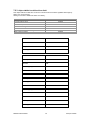
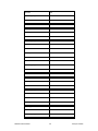
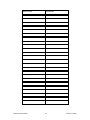
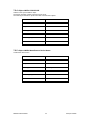
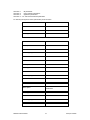
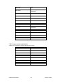
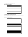
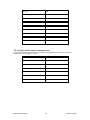
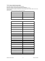
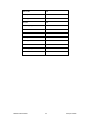
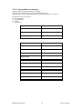
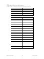
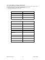
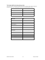
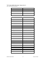
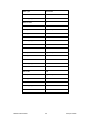
IO Module User Manual P.O.Box 164 Seven Hills 1730 NSW AUSTRALIA 05/08/2014 V1.0 Tel: +61 2 96248376 Fax: +61 2 9620 8709 Email: [email protected] Web: www.proconel.com Disclaimer Procon Electronics makes no representations or warranties with respect to the contents hereof. In addition, information contained herein are subject to change without notice. Every precaution has been taken in the preparation of this manual. Nevertheless, Procon Electronics assumes no responsibility, express or implied, for errors or omissions or any damages resulting from the use of the information contained in this publication. All trademarks belong to their respective owners. PROCON ELECTRONICS 2 CANopen PC6RO TABLE OF CONTENTS 1. INTRODUCTION ............................................................................................ 5 2. TECHNICAL SPECIFICATION ........................................................................... 6 3. PHYSICAL INFORMATION .............................................................................. 7 3.1 3.2 3.3 3.4 3.5 3.6 4. SETTING THE NODE ID AND BAUD RATE ...................................................... 10 4.1 4.2 4.3 4.4 4.5 5. CHANGING THE DIP SWITCH TO SET THE NODE ID AND BAUD RATE ....................................................... 10 SETTING THE NODE ID USING THE DIP SWITCHES ............................................................................... 11 SETTING THE BAUD RATE USING THE DIP SWITCHES ........................................................................... 11 SETTING THE NODE ID USING SOFTWARE.......................................................................................... 11 SETTING THE BAUD RATE USING SOFTWARE. ...................................................................................... 12 WIRING ...................................................................................................... 13 5.1 5.2 6. POWER SUPPLY AND COMMUNICATIONS WIRING .............................................................................. 13 WIRING THE RELAY OUTPUTS.......................................................................................................... 14 INDICATORS ............................................................................................... 15 6.1 6.2 6.3 7. PHYSICAL DIMENSIONS ................................................................................................................... 7 DIN RAIL BUS ADAPTOR .................................................................................................................. 8 INSTALLING THE MODULE ONTO THE DIN RAIL ..................................................................................... 8 REMOVING THE MODULE FROM THE DIN RAIL ..................................................................................... 9 GROUNDING/SHIELDING ................................................................................................................. 9 NETWORK TERMINATION ................................................................................................................ 9 FRONT PANEL INDICATORS ............................................................................................................. 15 RUN INDICATOR (R) ..................................................................................................................... 16 ERROR INDICATOR (T)................................................................................................................... 16 IMPLEMENTED CANOPEN OBJECTS ............................................................. 17 7.1 OBJECT BLOCK DIAGRAMS ............................................................................................................. 17 7.1.1 Block diagram for relay outputs ..................................................................................... 17 7.2 COMMUNICATION SEGMENT ......................................................................................................... 18 7.2.1 Object 1000h: Device Type ............................................................................................. 18 7.2.2 Object 1001h: Error Register .......................................................................................... 18 7.2.3 Object 1003h: Pre-defined Error Field ............................................................................ 19 7.2.4 Object 1005h: COB-ID SYNC............................................................................................ 22 7.2.5 Object 1008h: Manufacturer Device Name .................................................................... 22 7.2.6 Object 1009h: Manufacturer Hardware Version ............................................................ 23 7.2.7 Object 100Ah: Manufacturer Software Version ............................................................. 23 7.2.8 Object 100Ch: Guard Time ............................................................................................. 24 7.2.9 Object 100Dh: Life Time Factor ...................................................................................... 24 7.2.10 Object 1010h: Store Parameter Field ............................................................................. 25 7.2.11 Object 1011h: Restore Default Parameters .................................................................... 26 7.2.12 Object 1014h: COB-ID EMCY........................................................................................... 28 7.2.13 Object 1015h: Inhibit Time Emergency .......................................................................... 29 7.2.14 Object 1016h: Heartbeat Consumer Entries ................................................................... 29 7.2.15 Object 1017h: Producer Heartbeat Time........................................................................ 30 7.2.16 Object 1018h: Identity Object ........................................................................................ 31 7.2.17 Object 1029h: Error Behaviour ....................................................................................... 33 7.2.18 Object 1200h: Server SDO Parameter 1 ......................................................................... 34 7.2.19 Object 1400h: Receive PDO Communication Parameter 1............................................. 35 PROCON ELECTRONICS 3 CANopen PC6RO 7.2.20 Object 1600h: Receive PDO Mapping Parameter 1 ........................................................ 36 7.3 MANUFACTURER SEGMENT ........................................................................................................... 39 7.3.1 Object 2001h: Module ID................................................................................................ 39 7.3.2 Object 2002h: Module Baud Rate................................................................................... 39 7.3.3 Object 2003h: Module DIP Switch .................................................................................. 40 7.4 DEVICE PROFILE SEGMENT ............................................................................................................ 41 7.4.1 Object 6200h: Write State 6 Output Lines ...................................................................... 41 7.4.2 Object 6202h: Polarity 6 Output Lines ............................................................................ 42 7.4.3 Object 6206h: Error Mode 6 Output Lines ..................................................................... 43 7.4.4 Object 6207h: Fault State 6 Output Lines ....................................................................... 44 7.4.5 Object 6220h: Write State 1 Output Line 1-6 ................................................................. 45 8. SAFETY GUIDELINES .................................................................................... 47 8.1 8.2 8.3 8.4 INTRODUCTION ........................................................................................................................... 47 INTENDED USE ............................................................................................................................ 47 TRANSPORT AND STORAGE............................................................................................................. 47 INSTALLATION ............................................................................................................................. 47 PROCON ELECTRONICS 4 CANopen PC6RO 1. Introduction The PC6RO module has 6 normally open/ normally closed relay outputs. These modules may be used when a higher drive capability is required, or when isolation between outputs are required. The module plugs into a special bus connector which fits inside the DIN rail. The power supply voltage and the CAN bus signals are connected via this bus connector. The CAN interface is electrically isolated and is compliant with ISO 11898. The module has been equipped with status led’s which are used to indicate the status of the Inputs and communications. This visual indication assists with fault finding and diagnostics. The CANopen node ID and bit rate can be setup by DIP switches or software. PROCON ELECTRONICS 5 CANopen PC6RO 2. Technical Specification Power Supply Relay Outputs CANopen Data Temperature Connectors PROCON ELECTRONICS Logic Supply Voltage Logic Supply Current Output Points Maximum Current Isolation NMT Error Control Node ID Number of PDO PDO Modes PDO Mapping PDO Linking Number of SDO Error Message Operating Temperature. Storage Temperature Logic Power and Comms. Inputs 6 24 Vdc 71mA 6 1A @ 220VAC / 1A @ 28VDC 4000Vrms between field and logic 1500Vrms between outputs Slave Node Guarding / Consumer Heartbeat DIP switch or software 1 Rx Event Controlled Asynchronous, Event Timer Asynchronous, Sync - Acyclic, Sync – Cyclic. Variable Supported 1 Server Yes -20°C to + 70°C -40°C to + 85°C 5 way connector that clips onto DIN rail 6 x 3 Way screw connector on top and bottom CANopen PC6RO 3. Physical Information 3.1 Physical Dimensions The PC6RO enclosure is shown below. The module clips directly onto an industry standard DIN rail. Field wiring is on the top and bottom of the module via 6 plug-in connectors. The module power and CAN communications wiring is on a separate connector which clips onto the DIN rail on the back of the housing. Allow at least 25mm on top and below the module to accommodate the wiring. Ensure that enough space is kept above and below the module for good ventilation. 113.0mm 17.6mm 110.5mm PROCON ELECTRONICS 7 CANopen PC6RO 3.2 DIN rail Bus adaptor The BUS connector allows side-by-side installation of the Modules. The picture below shows multiple BUS connectors installed on a DIN rail. First, install the BUS connector onto the DIN rail, then slide into the adjacent BUS connector. 3.3 Installing the module onto the DIN rail The modules are designed to be installed on a standard 35 mm DIN rail. Snap the BUS connector first into the rail as shown above. Next clip the top of the module onto the DIN rail and pivot the Module onto the DIN rail. The spring loaded clasp will latch around onto the DIN resulting in a firmly seated product. Do not force the module onto the connector otherwise the module or connector may be damaged. Note: The modules are not designed for hot plug in. The power must be turned off before the modules are plugged into the base. PROCON ELECTRONICS 8 CANopen PC6RO 3.4 Removing the module from the DIN rail To remove the module from the DIN Rail, use a flat blade screwdriver to pry the spring loaded clasp away from the DIN rail in the manner shown in the picture below. Next pivot the module up and away from the DIN rail and remove. 3.5 Grounding/Shielding In most cases, the modules will be installed in an enclosure along with other devices which generate electromagnetic radiation. Examples of these devices are relays and contactors, transformers, motor controllers etc. This electromagnetic radiation can induce electrical noise into both power and signal lines, as well as direct radiation into the module causing negative effects on the system. Appropriate grounding, shielding and other protective steps should be taken at the installation stage to prevent these effects. These protective steps include control cabinet grounding, module grounding, cable shield grounding, protective elements for electromagnetic switching devices, correct wiring as well as consideration of cable types and their cross sections. 3.6 Network Termination Transmission line effects often present a problem on data communication networks. These problems include reflections and signal attenuation. To eliminate the presence of reflections from the end of the cable, the cable must be terminated at both ends with a resistor across the line equal to its characteristic impedance. Both ends must be terminated since the direction of propagation is bi-directional. This termination is typically 120 ohms. PROCON ELECTRONICS 9 CANopen PC6RO 4. Setting the Node ID and baud rate The DIP switches are provided to manually configure the module node ID and baud rate. Switches 1 through 5 set the node ID sequentially starting at 1 and ending at 31. Switches 6, 7 & 8 set the baud rate. When the ID switches are all set to zero, the ID is taken from internal memory. When the baud rate switches are all set to zero, the baud rate is taken from the internal memory. The user must first configure the module by writing the correct values to the module. 4.1 Changing the DIP switch to set the Node ID and baud rate The software in the module samples the dip switches on a reset when the power is cycled. Once sampled, the software writes the settings to the CAN port. The user is welcome to change the dip switches while the module is powered, however, a reset must be initiated afterward. The DIP switch can be toggled using a small flat blade screwdriver, or equivalent tool, as shown in the picture below. PROCON ELECTRONICS 10 CANopen PC6RO 4.2 Setting the Node ID using the DIP switches The following table assists with the setting up of DIP switches for the required NODE ID. NODE ID SW8 Software 1 2 3 4 4 6 31 - SW7 - SW6 - SWITCH SETTING SW5 SW4 SW3 Off Off Off Off Off Off Off Off Off Off Off Off Off Off On Off Off On Off Off On On On On SW2 Off Off On On Off Off On On SW1 Off On Off On Off On Off On 4.3 Setting the Baud Rate using the DIP switches The following table assists with the setting up of DIP switches for the required Baud Rate. BAUD RATE kbits/s SW8 Software Off 20 Off 50 Off 125 Off 250 On 500 On 800 On 1000 On SWITCH SETTING SW7 Off Off On On Off Off On On SW6 Off On Off On Off On Off On SW5 SW4 SW3 SW2 SW1 - - - - - 4.4 Setting the Node ID using software. In order to use the node ID from memory, ensure that all of the node ID dip switches are in the OFF position. Before the internal node id is selected, the user must first write the correct id value to the Module ID object in the manufacturer segment. The object address is 2001h. The node id can be configured from 1 to 127. PROCON ELECTRONICS 11 CANopen PC6RO 4.5 Setting the baud rate using software. In order to use the baud rate from memory, ensure that all of the baud rate dip switches are in the OFF position. Before the internal baud rate is selected, the user must first write the correct baud rate value to the Module Baud Rate object in the manufacturer segment. The object address is 2002h. The following baud rates are supported. BAUD RATE kbits/s 20 50 100 125 250 500 800 1000 PROCON ELECTRONICS OBJECT VALUE (2002h) 1 2 3 4 5 6 7 8 12 CANopen PC6RO 5. Wiring 5.1 Power supply and Communications Wiring The following diagram shows the wiring for the power and CAN communications. Terminal 1 2 3 Power 0V Power +24V CAN GND 4 5 CANL CANH PROCON ELECTRONICS Description The DC power supply 0V connection. The DC power supply positive connection. 12V to 24VDC. The CAN circuit is isolated from the DC power supply for the module. The CAN GND connection is not connected to the DC power supply GND. Use a separate ground wire to connect all of the CAN GND terminals on the modules together. This ensures that all of the modules are at the same potential. The ground wire must be earthed at one end only. CANL network connection CANH network connection 13 CANopen PC6RO 5.2 Wiring the relay outputs The following diagram shows how the relay contacts are connected to the wiring terminals. 1 2 3 4 5 6 7 8 9 10 11 12 13 14 15 16 17 18 1 2 3 4 5 6 PROCON ELECTRONICS 14 COM 1 N/C 1 N/O 1 COM 2 N/C 2 N/O 2 COM 3 N/C 3 N/O 3 COM 4 N/C 4 N/O 4 COM 5 N/C 5 N/O 5 COM 6 N/C 6 N/O 6 CANopen PC6RO 6. Indicators 6.1 Front panel indicators The CAN communications uses an error LED (T) and a run LED (R). The run LED indicates the CANopen state. The error LED is shows errors of the network. Power: CAN (R): CAN (T): Output Status: Flashes to indicate the CPU is running. Indicates the CANopen run state. Indicates a CANopen error. “OFF” when the output is off “ON” when the output is on. R = CANopen RUN state P = Power T = CANopen Error P Output Status 1-6 1 2 5 6 Switch 1 R T 3 4 6RO 1 2 3 4 5 6 7 8 OFF PROCON ELECTRONICS 15 Switch 8 ON CANopen PC6RO 6.2 Run indicator (R) RUN LED State Description Single flash STOPPED The device is in STOPPED state. Blinking PRE-OPERATIONAL The device is in PRE- OPERATIONAL state. On RUN The device is in RUN state. 6.3 Error indicator (T) ERROR LED State Description Off no error The device is in working condition. Single flash warning limit reached Double flash Error Control Event On Bus Off At least one of the error counters of the CAN controller has reached or exceeded the warning limit. A guard event (NMT- Slave or NMTMaster) or a Heartbeat event has occurred. The CAN controller is bus-off. PROCON ELECTRONICS 16 CANopen PC6RO 7. Implemented CANopen Objects 7.1 Object Block Diagrams 7.1.1 Block diagram for relay outputs PROCON ELECTRONICS 17 CANopen PC6RO 7.2 Communication Segment 7.2.1 Object 1000h: Device Type The device type specifies the kind of device. The lower 16 bit contain the device profile number and the upper 16 bit an additional information. INDEX 1000 Name Device Type Object Code Variable Data Type UNSIGNED32 Access CONST PDO Mapping No Default Value 0x00020191 7.2.2 Object 1001h: Error Register The error register is a field of 8 bits, each for a certain error type. If an error occurs the bit has to be set. Bit 0 1 2 3 4 5 6 7 Meaning generic error communication error (overrun, error state) - INDEX 1001 Name Error Register Object Code Variable Data Type UNSIGNED8 Access RO PDO Mapping No Default Value 0x00 PROCON ELECTRONICS 18 CANopen PC6RO 7.2.3 Object 1003h: Pre-defined Error Field This object holds errors that have occurred on the device and have been signalled via Emergency Object. It is an error history. Writing to sub index 0 deletes the entire error history. ERROR Communications Error CAN Overrun Error CAN in error passive Heart Beat or life guard error CAN recovered from bus-off PDO not processed due the length PDO length exceeded CODE 0x8100 0x8110 0x8120 0x8130 0x8140 0x8210 0x8220 INDEX 1003 Name Pre-defined Error Field Object Code Array Data Type UNSIGNED32 Sub-Index 000 Description Number of Errors Access RW PDO Mapping No Default Value 0x00000000 Sub-Index 001 Description Standard Error Field Data Type UNSIGNED32 Access RO PDO Mapping No Default Value 0x00000000 Sub-Index 002 Description Standard Error Field Data Type UNSIGNED32 PROCON ELECTRONICS 19 CANopen PC6RO Access RO PDO Mapping No Default Value 0x00000000 Sub-Index 003 Description Standard Error Field Data Type UNSIGNED32 Access RO PDO Mapping No Default Value 0x00000000 Sub-Index 004 Description Standard Error Field Data Type UNSIGNED32 Access RO PDO Mapping No Default Value 0x00000000 Sub-Index 005 Description Standard Error Field Data Type UNSIGNED32 Access RO PDO Mapping No Default Value 0x00000000 Sub-Index 006 Description Standard Error Field Data Type UNSIGNED32 Access RO PDO Mapping No PROCON ELECTRONICS 20 CANopen PC6RO Default Value 0x00000000 Sub-Index 007 Description Standard Error Field Data Type UNSIGNED32 Access RO PDO Mapping No Default Value 0x00000000 Sub-Index 008 Description Standard Error Field Data Type UNSIGNED32 Access RO PDO Mapping No Default Value 0x00000000 Sub-Index 009 Description Standard Error Field Data Type UNSIGNED32 Access RO PDO Mapping No Default Value 0x00000000 Sub-Index 010 Description Standard Error Field Data Type UNSIGNED32 Access RO PDO Mapping No Default Value 0x00000000 PROCON ELECTRONICS 21 CANopen PC6RO 7.2.4 Object 1005h: COB-ID SYNC COB-ID of the Synchronization object. The device generates a SYNC message if bit 30 is set. The meaning of other bits is equal to the other communication objects. INDEX 1005 Name COB-ID SYNC Object Code Variable Data Type UNSIGNED32 Access RW PDO Mapping No Default Value 0x00000080 7.2.5 Object 1008h: Manufacturer Device Name Contains the device name. INDEX 1008 Name Manufacturer Device Name Object Code Variable Data Type VISIBLE_STRING Access CONST PDO Mapping No Default Value PC6RO PROCON ELECTRONICS 22 CANopen PC6RO 7.2.6 Object 1009h: Manufacturer Hardware Version Contains the device hardware version. INDEX 1009 Name Manufacturer Hardware Version Object Code Variable Data Type VISIBLE_STRING Access CONST PDO Mapping No Default Value V01.00 7.2.7 Object 100Ah: Manufacturer Software Version Contains the device software version. INDEX 100A Name Manufacturer Software Version Object Code Variable Data Type VISIBLE_STRING Access CONST PDO Mapping No Default Value V01.00 PROCON ELECTRONICS 23 CANopen PC6RO 7.2.8 Object 100Ch: Guard Time This entry contains the guard time in milli-seconds. It is 0, if not used. INDEX 100C Name Guard Time Object Code Variable Data Type UNSIGNED16 Access RW PDO Mapping No Default Value 0x00000000 Unit ms 7.2.9 Object 100Dh: Life Time Factor The life time factor multiplied with the guard time gives the life time for the device. It is 0, if not used. INDEX 100D Name Life Time Factor Object Code Variable Data Type UNSIGNED8 Access RW PDO Mapping No Default Value 0x00000000 PROCON ELECTRONICS 24 CANopen PC6RO 7.2.10 Object 1010h: Store Parameter Field This entry supports saving of parameters in non-volatile memory. With a read access the device provides information about its saving capabilities. Several parameter groups are distinguished. Sub index 1 : all parameters Sub index 2 : communication parameters Sub index 3 : application parameters Sub index 4 - 127: manufacturer defined parameters For saving the signature "save" (0x65766173) must be written. The following parameters can be saved or loaded: Communication Parameter Object COB-ID SYNC Guard Time Life Time Factor COB-ID EMCY Heartbeat Consumer Entries Producer Heartbeat Time PDO length exceeded 1005h 100Ch 100Dh 1014h 1016h 1017h 1029h Manufacturer Specific Parameter Module ID Module Baud Rate Object 2001h 2002h Application Parameter Polarity 6 Output Lines Error Mode 6 Output Lines Fault State 6 Output Lines Object 6202h 6206h 6207h INDEX 1010 Name Store Parameter Field Object Code Array Data Type UNSIGNED32 Sub-Index 000 Description Number of Entries Access RO PDO Mapping No Default Value 0x4 Sub-Index 001 Description Save all Parameters PROCON ELECTRONICS 25 CANopen PC6RO Data Type UNSIGNED32 Access RW PDO Mapping No Default Value 0x00000000 Sub-Index 002 Description Save Communication Parameters Data Type UNSIGNED32 Access RW PDO Mapping No Default Value 0x00000000 Sub-Index 003 Description Save Application Parameters Data Type UNSIGNED32 Access RW PDO Mapping No Default Value 0x00000000 Sub-Index 004 Description Save Manufacturers Parameters Data Type UNSIGNED32 Access RW PDO Mapping No Default Value 0x00000000 7.2.11 Object 1011h: Restore Default Parameters This entry supports restoring of default parameters. With a read access the device provides information about its capabilities to restore these values. Several parameter groups are distinguished. PROCON ELECTRONICS 26 CANopen PC6RO Sub index 1 : all parameters Sub index 2 : communication parameters Sub index 3 : application parameters Sub index 4 - 127: manufacturer defined parameters For restoring the signature "load" (0x64616f6c) must be written. INDEX 1011 Name Restore Default Parameters Object Code Array Data Type UNSIGNED32 Sub-Index 000 Description Number of Entries Access RO PDO Mapping No Default Value 0x4 Sub-Index 001 Description Restore all Default Parameters Data Type UNSIGNED32 Access RW PDO Mapping No Default Value 0x00000000 Sub-Index 002 Description Restore Communication Default Parameters Data Type UNSIGNED32 Access RW PDO Mapping No Default Value 0x00000000 PROCON ELECTRONICS 27 CANopen PC6RO Sub-Index Description 003 Restore Application Default Parameters Data Type UNSIGNED32 Access RW PDO Mapping No Default Value 0x00000000 Sub-Index 004 Description Restore Manufacturers Default Parameters Data Type UNSIGNED32 Access RW PDO Mapping No Default Value 0x00000000 7.2.12 Object 1014h: COB-ID EMCY COB-ID used for emergency message (Emergency Producer). INDEX 1014 Name COB-ID EMCY Object Code Variable Data Type UNSIGNED32 Access RO PDO Mapping No Default Value 0x00000080 PROCON ELECTRONICS 28 CANopen PC6RO 7.2.13 Object 1015h: Inhibit Time Emergency Inhibit Time used for emergency message (Emergency Producer). The time has to be a multiple of 100 us. INDEX 1015 Name Inhibit Time Emergency Object Code Variable Data Type UNSIGNED16 Access RW PDO Mapping No Default Value 0x0 7.2.14 Object 1016h: Heartbeat Consumer Entries The consumer heartbeat time defines the expected heartbeat cycle time and thus has to be higher than the corresponding producer heartbeat time configured on the device producing this heartbeat. The bits 31 - 24 of each sub-index has to be 0. The bits 23 - 16 contain the node-id. The lower 16 bits contain the heartbeat time INDEX 1016 Name Heartbeat Consumer Entries Object Code Array Data Type UNSIGNED32 Sub-Index 000 Description Number of Entries Access RO PDO Mapping No Default Value 0x02 Sub-Index 001 Description Consumer Heartbeat Time 1 Data Type UNSIGNED32 PROCON ELECTRONICS 29 CANopen PC6RO Access RW PDO Mapping No Default Value 0x00000000 Sub-Index 002 Description Consumer Heartbeat Time 2 Data Type UNSIGNED32 Access RW PDO Mapping No Default Value 0x00000000 7.2.15 Object 1017h: Producer Heartbeat Time The producer heartbeat time defines the cycle time of the heartbeat. If the time is 0 it is not used. The time has to be a multiple of 1 msec INDEX 1017 Name Producer Heartbeat Time Object Code Variable Data Type UNSIGNED16 Access RW PDO Mapping No Default Value 0x00000000 PROCON ELECTRONICS 30 CANopen PC6RO 7.2.16 Object 1018h: Identity Object This object contains general information about the device. Sub-Index 1 contains a unique value allocated each manufacturer. Sub-Index 2 identifies the manufacturer specific product code (device version). Sub-Index 3 contains the revision number. Bit 31-16 is the major revision number and Bit 15-0 the minor revision number. Sub-Index 4 identified a manufacturer specific serial number. INDEX 1018 Name Identity Object Object Code Record Data Type IDENTITY Sub-Index 000 Description number of entries Access RO PDO Mapping No Default Value 0x4 Sub-Index 001 Description Vendor Id Data Type UNSIGNED32 Access RO PDO Mapping No Default Value 0x000003AD Sub-Index 002 Description Product Code Data Type UNSIGNED32 Access RO PDO Mapping No Default Value 0x0 PROCON ELECTRONICS 31 CANopen PC6RO Sub-Index 003 Description Revision number Data Type UNSIGNED32 Access RO PDO Mapping No Default Value 0x0 Sub-Index 004 Description Serial number Data Type UNSIGNED32 Access RO PDO Mapping No Default Value 0 PROCON ELECTRONICS 32 CANopen PC6RO 7.2.17 Object 1029h: Error Behaviour Sub index 000 contains the number of error classes. Sub index 001 contains the error class for a communication error. Sub indices 001 to 254 contain device profile or manufacturer specific error classes. The value of an error class can be: 0 = pre - operational 1 = no state change 2 = stopped 3 .. 127 reserved INDEX 1029 Name Error Behaviour Object Code Array Data Type UNSIGNED8 Sub-Index 000 Description Number of Entries Access RO PDO Mapping No Default Value 1 Sub-Index 001 Description Communication Error Data Type UNSIGNED8 Access RW PDO Mapping No Default Value 0x0 PROCON ELECTRONICS 33 CANopen PC6RO 7.2.18 Object 1200h: Server SDO Parameter 1 The object contains the parameters for the SDOs for which the device is the server. INDEX 1200 Name Server SDO Parameter 1 Object Code Record Data Type SDO_PARAMETER Sub-Index 000 Description Number of Entries Access RO PDO Mapping No Default Value 2 Sub-Index 001 Description COB-ID Client -> Server Data Type UNSIGNED32 Access RO PDO Mapping No Default Value 0x00000600 Sub-Index 002 Description COB-ID Server -> Client Data Type UNSIGNED32 Access RO PDO Mapping No Default Value 0x00000580 PROCON ELECTRONICS 34 CANopen PC6RO 7.2.19 Object 1400h: Receive PDO Communication Parameter 1 It contains the communication parameters of the current PDO the device is able to receive. Sub-index 0 contains the number of PDO-parameters implemented. Sub index 1 describes the COB-ID. If bit 31 is set the PDO is disabled. The transmission mode is defined by sub-index 2. An inhibit time can be defined on sub-index 3 in 100 us. At the 5th sub-index can be defined an event time for asynchronous pdos. INDEX Name 1400 Receive PDO Communication Parameter 1 Object Code Record Data Type PDO_COMM_PAR Sub-Index 000 Description Number of Entries Access RO PDO Mapping No Default Value 0x03 Sub-Index 001 Description COB-ID Data Type UNSIGNED32 Access RW PDO Mapping No Default Value 0x00000200 Sub-Index 002 Description Transmission Type Data Type UNSIGNED8 Access RW PDO Mapping No Default Value 0xFF PROCON ELECTRONICS 35 CANopen PC6RO Sub-Index 003 Description Inhibit Time Data Type UNSIGNED16 Access RW PDO Mapping No Default Value 0x0 Unit 100 us 7.2.20 Object 1600h: Receive PDO Mapping Parameter 1 The sub-indices contain the indices, the sub-indices and the lengths of the mapped sub-indices. Their structure is as follows: index (16bit) sub-index (8bit) length (8bit) INDEX Name 1600 Receive PDO Mapping Parameter 1 Object Code Record Data Type PDO_MAPPING Sub-Index 000 Description Number of Entries Access RW PDO Mapping No Default Value 0x08 Sub-Index 001 Description Mapping Entry 1 Data Type UNSIGNED32 Access RW PDO Mapping No Default Value 0x62000108 PROCON ELECTRONICS 36 CANopen PC6RO Sub-Index 002 Description Mapping Entry 2 Data Type UNSIGNED32 Access RW PDO Mapping No Default Value 0x00050008 Sub-Index 003 Description Mapping Entry 3 Data Type UNSIGNED32 Access RW PDO Mapping No Default Value 0x00050008 Sub-Index 004 Description Mapping Entry 4 Data Type UNSIGNED32 Access RW PDO Mapping No Default Value 0x00050008 Sub-Index 005 Description Mapping Entry 5 Data Type UNSIGNED32 Access RW PDO Mapping No Default Value 0x00050008 Sub-Index 006 Description Mapping Entry 6 PROCON ELECTRONICS 37 CANopen PC6RO Data Type UNSIGNED32 Access RW PDO Mapping No Default Value 0x00050008 Sub-Index 007 Description Mapping Entry 7 Data Type UNSIGNED32 Access RW PDO Mapping No Default Value 0x00050008 Sub-Index 008 Description Mapping Entry 8 Data Type UNSIGNED32 Access RW PDO Mapping No Default Value 0x00050008 PROCON ELECTRONICS 38 CANopen PC6RO 7.3 Manufacturer Segment 7.3.1 Object 2001h: Module ID INDEX 2001 Name Module ID Object Code Variable Data Type UNSIGNED8 Access RW PDO Mapping No Default Value 0x7F 7.3.2 Object 2002h: Module Baud Rate INDEX 2002 Name Module Baud Rate Object Code Variable Data Type UNSIGNED8 Access RW PDO Mapping No Default Value 0x04 PROCON ELECTRONICS 39 CANopen PC6RO 7.3.3 Object 2003h: Module DIP Switch INDEX 2003 Name Module DIP Switch Object Code Variable Data Type UNSIGNED8 Access RO PDO Mapping No Default Value 0x00 PROCON ELECTRONICS 40 CANopen PC6RO 7.4 Device Profile Segment 7.4.1 Object 6200h: Write State 6 Output Lines Sets a group of 6 output lines as a byte of information. INDEX 6200 Name Write State 6 Output Lines Object Code Array Data Type UNSIGNED8 Sub-Index 000 Description Number of Elements Access RO PDO Mapping No Default Value 0x1 Sub-Index 001 Description digital Outputs 1-6 Data Type UNSIGNED8 Access RWW PDO Mapping Yes Default Value 0 PROCON ELECTRONICS 41 CANopen PC6RO 7.4.2 Object 6202h: Polarity 6 Output Lines Defines the polarity of a group of 6 output lines. INDEX 6202 Name Polarity 6 Output Lines Object Code Array Data Type UNSIGNED8 Sub-Index 000 Description Number of Elements Access RO PDO Mapping No Default Value 0x1 Sub-Index 001 Description Polarity for digital Outputs 1-6 Data Type UNSIGNED8 Access RW PDO Mapping No Default Value 0x00 PROCON ELECTRONICS 42 CANopen PC6RO 7.4.3 Object 6206h: Error Mode 6 Output Lines This object indicates, whether an output is set to a pre-defined error value (see 6207 h object) in case of an internal device failure or a 'Stop Remote Node' indication. 1 = output value shall take the pre-defined condition specified in 6207 h object 0 = output value shall be kept if an error occurs INDEX 6206 Name Error Mode 6 Output Lines Object Code Array Data Type UNSIGNED8 Sub-Index 000 Description Number of Elements Access RO PDO Mapping No Default Value 0x1 Sub-Index 001 Description Fault Mode for digital Outputs 16 Data Type UNSIGNED8 Access RW PDO Mapping No Default Value 0x3F PROCON ELECTRONICS 43 CANopen PC6RO 7.4.4 Object 6207h: Fault State 6 Output Lines Output line fault state. This defines the default output state on detecting a fault condition. Defined for groups of 8 outputs. The corresponding bit must be set in the default output line mode. INDEX 6207 Name Fault State 6 Output Lines Object Code Array Data Type UNSIGNED8 Sub-Index 000 Description Number of Elements Access RO PDO Mapping No Default Value 0x1 Sub-Index 001 Description Fault State for digital Outputs 16 Data Type UNSIGNED8 Access RW PDO Mapping No Default Value 0x00 PROCON ELECTRONICS 44 CANopen PC6RO 7.4.5 Object 6220h: Write State 1 Output Line 1-6 Sets a single output line information. INDEX 6220 Name Write State 1 Output Line 1-6 Object Code Array Data Type BOOLEAN Sub-Index 000 Description Number of Elements Access RO PDO Mapping No Default Value 0x6 Sub-Index 001 Description digital Output 1 Data Type BOOLEAN Access RWW PDO Mapping No Default Value 0 Sub-Index 002 Description digital Output 2 Data Type BOOLEAN Access RWW PDO Mapping No Default Value 0 Sub-Index 003 Description digital Output 3 PROCON ELECTRONICS 45 CANopen PC6RO Data Type BOOLEAN Access RWW PDO Mapping No Default Value 0 Sub-Index 004 Description digital Output 4 Data Type BOOLEAN Access RWW PDO Mapping No Default Value 0 Sub-Index 005 Description digital Output 5 Data Type BOOLEAN Access RWW PDO Mapping No Default Value 0 Sub-Index 006 Description digital Output 6 Data Type BOOLEAN Access RWW PDO Mapping No Default Value 0 PROCON ELECTRONICS 46 CANopen PC6RO 8. SAFETY GUIDELINES 8.1 Introduction The IO Modules have been designed developed or manufactured for conventional use in industry. They were not designed, developed and manufactured for any use involving serious risks or hazard s that without the implementation of exceptionally stringent safety precautions could lead to death, injury, serious physical damage or loss of any other kind . Such risks and hazard s include in particular the use of these devices to monitor nuclear reactions in nuclear power plants, as well as flight control system s, flight safety, the control of mass transportation system s, medical life support system s, and the control of weapons system s. When using IO Modules with programmable logic controllers and when using operating and monitoring devices as control system s in conjunction with a Soft PLC, the safety precautions app lying to industrial control system s (e.g. the provision of safety devices such as emergency stop circuits, etc.) in accordance with applicable national and international regulations must be observed. The same app lies for all other devices connected to the system, such as drives. All tasks such as installation, commissioning and service may only be carried out by qualified personnel. Qualified personnel are persons who are familiar with the transport, mounting, installation, commissioning and operation of the product and have the appropriate qualifications. National accident prevention guidelines must be followed. The safety guidelines, connection descriptions and limit values listed in the technical data must be read carefully before installation and commissioning and must be observed. 8.2 Intended Use Electronic devices are generally not fail-safe. In the event of a failure on the IO Modules, operating or monitoring device or uninterruptible power supply, the user is responsible for ensuring that other devices that may be connected, such as motors, are made safe. 8.3 Transport and Storage During transport and storage, devices must be protected from excessive stress (mechanical load, temperature, humidity, aggressive atmosphere). 8.4 Installation The installation must take place according to the documentation. The IO Modules are only allowed to be installed wit out voltage app lied and by qualified personnel. General safety regulations and nationally applicable accident prevention guidelines must be observed. Electrical installation must be carried out according to the relevant guidelines (e.g. line cross section, fuse, protective ground connection). PROCON ELECTRONICS 47 CANopen PC6RO