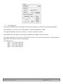
1
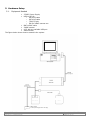
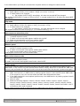
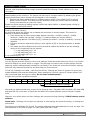
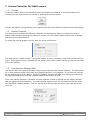
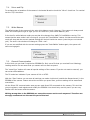
IMAGING SOLUTIONS INC. Original Equipment Manufacturer User Manual 2XB45 Control Software USB to I2C Drivers 20B45 21B45 20B45M 21B45M Prior to Using This Document: Videology reserves the right to modify the information in this document as necessary and without notice. It is the user’s responsibility to be certain they possess the most recent version of this document by going to www.videologyinc.com, searching for the model number, and comparing revision letters on the respective document, located in the document’s footer. For technical assistance with this product, please contact the supplier from whom the product was purchased. Videology® Imaging Solutions, Inc. 37M Lark Industrial Parkway Greenville, Rhode Island 02828 USA Tel: (401) 949 – 5332 Fax: (401) 949 – 5276 North/South American Sales: [email protected] www.videologyinc.com Doc # INS-11004 Revision: Preliminary B Videology® Imaging Solutions, Europe B.V. Neutronenlaan 4 5405 NH Uden, The Netherlands Tel: +31 (0) 413 256261 Fax: +31 (0) 413 251712 European Sales: [email protected] www.videology.nl Issue Date: 06/19/2014 Page 1 of 15 License Agreement (Software): This Agreement states the terms and conditions upon which Videology Imaging Solutions, Inc. USA and Videology Imaging Solutions, B.V. Europe (hereafter referred to as "Videology®") offer to license to you the software together with all related documentation and accompanying items including, but not limited to, the executable programs, drivers, libraries, and data files associated with such software. The Software is licensed, not sold, to you for use only under the terms of this Agreement. Videology grants to you, the purchaser, the right to use all or a portion of this Software provided that the Software is used only in conjunction with Videology's family of products. In using the Software you agree not to: • Decompile, disassemble, reverse engineer, or otherwise attempt to derive the source code for any Product (except to the extent applicable laws specifically prohibit such restriction); • Remove or obscure any trademark or copyright notices. Limited Warranty (Hardware and Software): ANY USE OF THE SOFTWARE OR HARDWARE IS AT YOUR OWN RISK. THE SOFTWARE IS PROVIDED FOR USE ONLY WITH VIDEOLOGY'S HARDWARE. THE SOFTWARE IS PROVIDED FOR USE "AS IS" WITHOUT WARRANTY OF ANY KIND, TO THE MAXIMUM EXTENT PERMITTED BY LAW, VIDEOLOGY DISCLAIMS ALL WARRANTIES OF ANY KIND, EITHER EXPRESS OR IMPLIED, INCLUDING, WITHOUT LIMITATION, IMPLIED WARRANTIES OR CONDITIONS OF MERCHANTABILITY, QUALITY AND FITNESS FOR A PARTICULAR APPLICATION OR PURPOSE. VIDEOLOGY IS NOT OBLIGATED TO PROVIDE ANY UPDATES OR UPGRADES TO THE SOFTWARE OR ANY RELATED HARDWARE. Limited Liability (Hardware and Software): In no event shall Videology or its Licensor's be liable for any damages whatsoever (including, without limitation, incidental, direct, indirect, special or consequential damages, damages for loss of business profits, business interruption, loss of business information, or other pecuniary loss) arising out of the use or inability to use this Software or related Hardware, including, but not limited to, any of Videology's family of products. Doc # INS-11004 Revision: Preliminary B Issue Date: 06/19/2014 Page 2 of 15 Table of Contents Document History .................................................................................................................... 3 Introduction ............................................................................................................................ 3 Installing the USB to I2C Drivers ................................................................................................ 4 Installing the Camera Control Software ...................................................................................... 4 Hardware Setup ...................................................................................................................... 5 5.1. Equipment Needed ............................................................................................................ 5 5.2. I2C Board Connections !IMPORTANT! ................................................................................. 6 6. Camera Modes ........................................................................................................................ 9 7. Camera Control for 20/21B45 camera ...................................................................................... 12 7.1. Connect ......................................................................................................................... 12 7.2. Overlay Functions ........................................................................................................... 12 7.3. Auto Exposure Settings (AEX) .......................................................................................... 12 7.4. Mirror and Flip ................................................................................................................ 13 7.5. White Balance ................................................................................................................ 13 7.6. General Communication ................................................................................................... 13 7.7. I2C Addresses ................................................................................................................ 14 8. Contact Information ............................................................................................................... 15 1. 2. 3. 4. 5. 1. Document History Revision A B Issue Date Reason 10-09-13 Initial release 06-10-14 Section 5.2 update CN# 13-0063 14-0062 2. Introduction The purpose of this document is to instruct the user on how to modify the settings and control the Videology 2xB45 camera. The flow will be as follows: A. Initial • • • Setup Installation of software/ files needed Hardware setup Driver(s) installation B. Register Modification • Modify Register settings using the GUI interface • Modify Sensor settings using the GUI interface Additional Equipment Needed: All the necessary hardware has been supplied with the exception of • A PC with an available USB port • Video Monitor • Power supply • BNC cable Doc # INS-11004 Revision: Preliminary B Issue Date: 06/19/2014 Page 3 of 15 3. Installing the USB to I2C Drivers 1. Run the self-extracting executable on the CD, “SW for 2xB45.exe” 2. This will create two folders: a. “C:\Videology Imaging Solutions\Videology Camera Control Program for 2xB45 camera” b. “C:\Videology Imaging Solutions\Videology USB to I2C Board Driver Software” 3. Plug the USB to I2C cable into the PC 4. When asked for a location of the driver point to: a. for 32-bit windows Operating systems C:\Videology Imaging Solutions\Videology USB to I2C Board Driver Software\Driver\i386 or b. for 64-bit windows Operating systems C:\Videology Imaging Solutions\Videology USB to I2C Board Driver Software\Driver\amd64 5. If the above step does not work, i.e. if Windows comes back and tells you that it could not find the driver software, then point to the following: C:\Videology Imaging Solutions\Videology USB to I2C Board Driver Software\ 4. Installing the Camera Control Software There is nothing to install. When the file “SW for 2xB45.exe” was run, the latest version of the control program and its DLL was placed in: C:\Videology Imaging Solutions\Videology Camera Control Program for 2xB45 camera As long as the executable file “BD_camControl.exe” and the DLL “Vdiicdll.dll” are located in the same directory, you just need to double click on the executable file to run the program. Doc # INS-11004 Revision: Preliminary B Issue Date: 06/19/2014 Page 4 of 15 5. Hardware Setup 5.1. Equipment Needed • • • • • • The figure below shows 3.3VDC Power Supply USB to I2C Kit o 60C1062 cable o 60C1045 cable o 72V0070 pcb o SW for 2xB45 camera.exe BNC to BNC cable 2XB45 camera A PC with an available USB port Video Monitor how to assemble the system. 7 p I n J S T 2XB45 camera 3.3VDC Doc # INS-11004 Revision: Preliminary B monitor 2XB45 camera 3.3VDC power supply with 2.1mm plug Issue Date: 06/19/2014 Page 5 of 15 5.2. I2C Board Connections !IMPORTANT! 60C1045 60C1062 7pin cable (connects to camera, 2 LEDs side of I2C board) 6pin cable (connects to computer, 1 LED side of I2C board) Using these figures as reference, follow the steps outlined below: • Lay out the Camera, USB-I2C interface board (72V0070), computer and monitor on your work area • Locate the 72V0070 USB to I2C Interface board Plug into camera 7pin 60C1045 1 LED 72V0070 2 LEDs • Plug into PC 6pin 60C1062 Connect the 7pin 60C1045 cable to the USB-I2C interface board CAUTION: ensure you are not using the 6pin 60c1062 cable for this connector! Damage to USB camera may occur! CAUTION: Use 7pin connector to camera The top LED will flicker when choosing commands The Second LED will stay on when there is an error 2 LEDs Doc # INS-11004 Revision: Preliminary B Issue Date: 06/19/2014 Page 6 of 15 • Connect the 6pin 60C1062 cable to the USB-I2C interface board DO NOT CONNECT THIS TO THE PC YET… CAUTION: Use 6pin connector to computer LED is on when USB cable is connected 1 LED • • Connect the 3.3VDC power supply to the 60C1045 cable Connect the BNC to BNC cable to the monitor and to the 60C1045 cable Doc # INS-11004 Revision: Preliminary B Issue Date: 06/19/2014 Page 7 of 15 60C1045 7 pin to I2C board Power (red) CVBS video plug (yellow) Plug into camera 6pin 60C1045 72V0070 60C1062 6 pin to I2C board USB 2.0 to PC Doc # INS-11004 Revision: Preliminary B Issue Date: 06/19/2014 Page 8 of 15 6. Camera Modes Using the GUI below, camera settings can be modified and stored. NOTE: Camera power must be cycled to verify settings have been stored correctly. Please note: Videology will not give any warranty in case settings are stored incorrectly, or settings are overwritten! Doc # INS-11004 Revision: Preliminary B Issue Date: 06/19/2014 Page 9 of 15 In the tables below you find per command the required actions to change the camera mode: Mirror mode: 1. Read register 0x3254 2. Read register 0x301c (mirror status = bit[0] (0=normal, 1=mirror) 3. If mode needs to be changed a. Set register 0x301c bit[0] accordingly. All other bits should NOT be changed. Set register 0x3254 bit[0]. Incase of mirror b[0]=1, in normal mode b[0]=0. All other bits should NOT be changed. Flip mode: 1. Read register 0x3254. 2. Read register 0x301c (flip status = bit[1] (0=normal, 1=flip) 3. If mode needs to be changed: a. Set register 0x301c bit[1] accordingly. All other bits should not be changed. Set register 0x3254. In case of flip b[1] = 1, in normal mode b[1] = 0; Auto exposure saturation point 1. Read register 0xa804 to check if the camera is in AEX mode. Value 0x000f is AEX mode, 0x0000 is manual exposure mode. 2. If mode is not correct load register 0xa804 with 0x000f. 3. Read current saturation point from register 0xa812 Load register 0xa812 with the new saturation level data Shutter speed 1. Read register 0xa804 to check if the camera is in manual mode. Value 0x000f is AEX mode, 0x0000 is manual exposure mode. 2. If mode is not manual load register 0xa804 with 0x0000. 3. Read current shutter value from register 0x3012. Load register 0x3012 with the new shutter value Auto white balance mode 1. Read the current white balance mode status from register 0xac04 (if value is 0x00ff than it is Auto white balance mode). If mode is not correct load register 0xac04 with value 0x00ff. Freeze mode: To use this mode the camera must be first put in the freeze mode. The camera first needs to run in AWB mode. It will look for the most optimal white balance setting. When this is reached the AWB must be hold, and preferable the R/B gains must be stored and used when the camera is powered up again. Put the camera in the freeze mode: 1. Make sure camera is in AWB mode by reading register 0xac04. Value 0x00ff means AWB mode. If the camera is not in the correct mode see table Auto White balance Mode. 2. If the AWB reached it’s most optimal position stop the AWB function by loading register 0xac04 with value 0x0000. 3. Wait 10 mSec. 4. Read the following registers: 0xac02, 0xac04, 0xac0a, 0xac0c, 0xac0e, 0xac10, 0xac12, 0xac14, 0xac16, 0xac18, 0xac10, 0xac1a, 0xac1c, 0xac1e, 0xac32, 0xac36, 0xac38, 0xac3a, 0xac3c, 0xac3e, 0xac40, 0xac42, 0xac44, 0xac46, 0xac48, 0xac4a, 0xac4c and 0xac4e. wait 5 mS between each read command. These values must be stored so that the can be loaded when the camera is powered up. Doc # INS-11004 Revision: Preliminary B Issue Date: 06/19/2014 Page 10 of 15 Enable or disable overlay In the camera 4 overlay images can be stored. Depending on the situation overlay’s can be enabled or disabled. Note that these overlay images must be loaded by Videology. Please contact us for more information. Global enabling of the overlay’s: The camera can have up to 4 images loaded. By disabling the global overlay functions all active overlays will be stopped in one command. 1. Read current status global overlay by reading register 0x4f02. If the MSbit (b[15] is set the global overlay is active. This does not mean that the overlays are visible. Also the individual overlay must be active to make the visible. Enable the global overlay by loading register 0x4f02 with value 0x8000, or disable global overlay by loading register 0x4f02 with 0x0000. Enabling individual overlays: As mentioned above the camera can be loaded with maximum 4 overlay images. This can all be enabled or disabled individually. 1. Each overlay has its own overlay enable address. Overlay1 = 0x4f08, overlay2 = 0x4f0a, overlay3 = 0x4f0c and overlay4 = 0x4f0e. To read the status per overlay read the corresponding address. The MSbit (b[15]) indicates the status. 1 overlay is enabled, 0 overlay is disabled. 2. Set each overlay as required by setting in each register b[15] to the desired enable or disable mode. 3. The lowest two bits indicates which overlay should be loaded. We advise to use the following values for the lowest two bits per register: • in reg 0x4f08b[1,0] = 00 • in reg 0x4f0ab[1,0] = 01 • in reg 0x4f0cb[1,0] = 10 in reg 0x4f0eb[1,0] = 3 If settings need to be stored: You can use the camera’s EEprom to store your settings. Please be careful when you do this. The camera has an 8K EEprom on board, which is 4 pages. The last page is meant to store certain settings. But this page may contain settings already stored from the factory! You should not overwrite the factory settings, since this may influence the start up and final behavior of the camera! To find out if settings are loaded , read from the EEProm. Settings are stored in groups of 4 bytes (two register address bytes and two data bytes). Keep reading until you find a group of 4 bytes with all 0xff. Here you should start storing your values. Do not leave unused spaces!!! In figure two you find a graphical example: addr data 0x0 D1 0x 1 D2 0x 2 D3 0x 3 D4 0x 4 0xff 0x 5 0xff 0x 6 0xff 0x 7 0xff 0x 8 0xff 0x 9 0xff 0xa 0xff First address to load your settings Figure 1. Note that you always should store 4 bytes in the following order: Reg Addr MSB, Reg.Addr LSB, Data MSB and Data LSB. So in the case of figure two the MSB of the register address must be stored in register 0x04. Please be very careful when you store settings. We recommend using Videology’s 2XB45 camera control software. Please note: Videology will not give any warranty in case settings are stored incorrectly, or settings are overwritten! The Eeprom has a different I2C format. The register addresses and data addresses are only one byte. The device address for the EEProm page 4 is 0xa6 (write) and 0xa7 (read). Doc # INS-11004 Revision: Preliminary B Issue Date: 06/19/2014 Page 11 of 15 7. Camera Control for 20/21B45 camera 7.1. Connect In case the camera was not connected yet when the software was started, or a communication error occurred you can re-connect to the camera by pushing the connect button. The tool will load the configuration from the camera and will set the buttons and check boxes accordingly. 7.2. Overlay Functions The camera can be loaded with maximal 4 different overlay graphics. Please note that they must be loaded inside the camera during the production process. For more details please contact your Videology customer service representative. To control the overlay graphics you can click one of the check boxes: The check box for "enable overlay" is the global enable. If this is unchecked, none of the overlays will be visible. If the global overlay is checked you can select via the other 4 which overlay you want to be visible (if they are loaded). 7.3. Auto Exposure Settings (AEX) The camera offers two types of exposure: they are auto exposure and manual exposure. The camera will run in Auto exposure mode if the check box “Manual Exposure" is not checked. In this case the user can set the working point of the camera. Either by changing the scroll-bar AEX ref or editing the edit box at the right hand side of the scroll-bar. Nominal value for this setting is 0x48. In the case manual Exposure is checked, the auto exposure routine is stopped and the camera will stay with the gain at its current position. The rolling shutter exposure time can be controlled with the scrollbar "Man.Shutt” (Manual shutter). This can also be done with the edit box at the right hand side of the scroll-bar. Doc # INS-11004 Revision: Preliminary B Issue Date: 06/19/2014 Page 12 of 15 7.4. Mirror and Flip To exchange the orientation of the camera in horizontal direction check the "Mirror" check box. For vertical use the "Flip" check box. 7.5. White Balance The default mode for the camera is the auto white balance mode. However, if the camera is always used under one fixed specific type of light you can un-check the ( Auto White Balance) box. In the box for white balance mode you see that this changes from AWB! To Push2White running. This means that the auto mode is still running till you push the "Push2White" button. At that moment the auto mode will stop and the current reached settings will be hold inside the sensor (note they are not stored yet!). The text in the window will change to "P2W = set". If you are not satisfied with the current settings press the "Push2White" button again, the system will start running again. 7.6. General Communication In this block you can load if required an EEPROM file. Only use a file that you received from Videology. Loading another file can cause that you camera will not work anymore! The "erase Eepr" button will erase all special settings of the camera. If you do not want to erase all, you can set an offset address. The TV mode box indicates if your camera is PAL or NTSC. With the "Save" button you can save all settings you made via this tool (outside the General area!) in the EEPROM of the camera. Please note at the moment you press Save, previous setting will be erased and overwritten. Via the Direct I2C communication area you can send direct I2C commands to the camera. This tool lets you set registers, read registers and modify the EEPROM. You should only use this part if you are very familiar with the sensor and the camera. Writing wrong data to the EEPROM can cause the camera not to work anymore! Therefore we strongly recommend not the use this part of the tool. Doc # INS-11004 Revision: Preliminary B Issue Date: 06/19/2014 Page 13 of 15 7.7. I2C Addresses If you want to develop you own software to control the camera you need to know the following details: Communication to the sensor: I2C write address = 0xBA, read address = 0xBB. The register addresses are 16 bits (2 bytes- 2 x 8 bits). Also data is 16 bits. The EEPROM uses max 8Kbites. These 8K are divided over 4 pages of each 256 bytes. The register addresses of the eeprom are 8 bites (one byte). This is also the case of for the data. However page write and read can be done on the eeprom. The addresses are: page 0 : write page 1 : write page 2 : write page 3 : write 0xa0 0xa2 0xa4 0xa6 Doc # INS-11004 Revision: Preliminary B read read read read 0xa1 0xa3 0xa5 0xa7 Issue Date: 06/19/2014 Page 14 of 15 8. Contact Information For technical assistance with this product, please contact the supplier from whom the product was purchased. For OEM inquiries, contact Videology® Imaging Solutions: Americas, Middle East, Far East & Australia: Videology® Imaging Solutions Inc. 37M Lark Industrial Parkway Greenville, RI 02828 USA Tel: (401) 949-5332 Fax: (401) 949-5276 Europe & N. Eurasia: Videology® Imaging Solutions Europe B.V. Neutronenlaan 4 5405 NH Uden The Netherlands Tel: +31 (0) 413-256261 Fax: +31 (0) 413-251712 Please visit our website: videologyinc.com VIDEOLOGY IMAGING SOLUTIONS is an ISO 9001 registered video camera developer and manufacturer serving industrial, machine vision, biometric, security, and specialty OEM markets. Videology designs, develops, manufactures, and distributes video, image acquisition, and display technologies and products to OEMs worldwide. Doc # INS-11004 Revision: Preliminary B Issue Date: 06/19/2014 Page 15 of 15