1
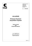
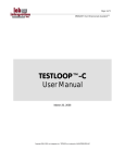
Opal-RT Technologies
2009
CAN-AC2 SOLUTION FOR REAL-TIME
SIMULATION WITH RT-LAB
This document explains how to use the CAN-AC2 (PCI) Softing card in a real-time
simulation using RT-LAB. It describes what are the steps in order to send a CAN
message, to receive a CAN message, to monitor a CAN bus and what are the hardware
requirements to communicate with an external device.
All the blocks referred to in this document can be found under the following Simulink
library: RT-LAB I/O / Softing / CANAC2-PCI
Detailed example models can be found under:
C:\Opal-rt\RT-LABx.x.x\Examples\IO\Softing\CANAC2-PCI
Technical Support
1
Opal-RT Technologies
2009
Send a CAN message
¾ Add an OpCanAc2-PCI_Ctl block in your model. This is the “controller” block.
The OpCanAc2 Controller block is used to define the settings of a CANbus
physical port. Only one controller is allowed per port and a controller is necessary
in order for a port to work with RT-LAB. Therefore, if the CAN card used has 2
ports, 2 controllers are required in order to set them and make them functional.
They can both have different settings as each controller block is unique.
¾ Open the controller block and set its parameters depending on your specific
application. Most top parameters are basic fields that allow the user to select to
which card / which port he wants to assign this controller block. These settings
are roughly defined by the hardware specs of the card (model, location in the
target PC, etc) in the system and they are already defined in the System
Integration documentation provided with the customer’s system at delivery. More
detailed parameters are available for those who need to implement a specific HIL
solution with the CAN card. See Appendix A.
¾ Add an OpCanAc2 Send block in your model. This is the “send” block. This
block allows transmission of a CAN message. The block refers to a physical port
that is configured in the controller block through the “Controller ID” parameter.
¾ Open the send block and set its parameters depending on your specific
application. The “Controller ID” parameter of the send block must match the
“Controller ID (shared with RECV and SEND blocks)” from the controller block.
Technical Support
2
Opal-RT Technologies
2009
This allows RT-LAB to associate a send block with a controller, and therefore a
send block with a physical port of the card. More detailed parameters are
available on how to set the width or the data packing of the messages to send. See
Appendix B.
¾ Connect the inputs and outputs of the send block.
¾ As one send block per message ID is required, the user must/can insert multiple
send blocks if there is a need to send messages on various IDs. They must all be
associated to the same controller if the user expects to send all those messages on
the same physical port of the card.
Technical Support
3
Opal-RT Technologies
2009
Receive a CAN message
¾ Add an OpCanAc2-PCI_Ctl block in your model. This is the “controller” block.
Open the controller block and set its parameters depending on your specific
application. See more detailed information about this block in the “Send a CAN
message” section or in Appendix A. Note that if a physical port of a card is meant
to send AND to receive data, only one controller block can be assigned to this
port. Both the send and the receive blocks will refer to a single controller ID as
they are all associate with the same port.
¾ Add an OpCanAc2 Recv block in your model. This is the “receive” block.
Open the receive block and set its parameters depending on your specific
application. The “Controller ID” parameter of the receive block must match the
“Controller ID (shared with RECV and SEND blocks)” from the controller block.
This allows RT-LAB to associate a receive block with a controller, and therefore
a receive block with a physical port of the card. More detailed parameters are
available on how to set the width of the data received and how to do some scaling
on it. See Appendix C.
¾ Connect the outputs of the receive block.
¾ As one receive block per message ID is required, the user must/can insert multiple
receive blocks if there is a need to receive messages on various IDs. They must all
be associated to the same controller if the user expects to receive all those
messages on the same physical port of the card.
Technical Support
4
Opal-RT Technologies
2009
Monitor a CAN bus
¾ Add an OpCanAc2-PCI_Ctl block in your model. Open the controller block and
set its parameters depending on your specific application. See more detailed
information about this block in the “Send a CAN message” section or in
Appendix A.
¾ Add an OpCanAc2 Monitor block in your model. This is the “monitoring”
block. It monitors all transactions on a CAN port of a CAN-AC2 card. Open the
monitoring block and set its parameters depending on your specific application.
The “Controller ID” parameter of the receive block must match the “Controller ID
(shared with RECV and SEND blocks)” from the controller block. This allows
RT-LAB to associate a monitoring block with a controller, and therefore a
monitoring block with a physical port of the card. Basic parameters allow the user
to choose the expected number of packet to receive and in what format should the
data be unpacked. More detailed parameters are available on how to use a log file
for monitoring. See Appendix D.
¾ Connect the outputs of the receive block.
¾ As one monitoring block per physical port is required, the user must/can insert
two monitoring blocks if there is a need to monitor both ports of the card.
Technical Support
5
Opal-RT Technologies
2009
Hardware Requirements
Once the modeling side is done and the card is ready to send/receive, the user must make
sure he meets the CAN communication hardware requirements in order to exchange data
on a CAN bus. In a classic configuration:
¾ 120 resistors must be placed at each end of the network.
¾ CAN-AC2 PCI from Softing already contains these resistors for both ports. The
DIP switches located on the PCI bracket must be turned on to insert the onboard
resistor into the circuit. There is one DIP switch per port. Such a CAN network
can be represented as:
The CAN-AC2 Softing PCI card has DB9 connectors for each channel. The associated
pinout is the following:
More information is available on the hardware requirements for users of the Single Wire
mode. See Help file of the OpCanAc2-PCI_Ctl block.
Technical Support
6
Opal-RT Technologies
2009
Technical Specifications Example
This example shows the link between CAN bus specs and how to implement a real-time
solution using the CAN-AC2 PCI Softing card and RT-LAB. Here is a table containing
fictive customer specs about what he needs to send, receive and monitor on a CAN bus.
The RT-LAB Simulink model attached with this document (TSE.mdl) contains multiple
comments so the user can quickly get the relation between the specs and how the model
is parameterized.
Physical Port #1 (Baud Rate = 250kBauds)
Messages to SEND
ID (hex) Rate (ms)
[10000 20000]
0x200
10
Messages to RECEIVE ID (hex) Rate (ms)
[65000 55 45 35]
0x300
5
Physical Port #2 (Baud Rate = 500 kBauds)
Messages to SEND
ID (hex)
Rate (ms)
[1 2 3 4 5 6 7 8]
0x400
20
Messages to RECEIVE
ID (hex)
Rate (ms)
None
N/A
N/A
Additional Requirements
Would like to have a saved log file of data packets of the sent messages. These packets
should be saved only when a specified condition is met. The file should contain the 17
consecutive data packets following the trigger and 3 packets before.
Technical Support
7
Opal-RT Technologies
2009
APPENDIX A - Controller Block
The following appendix contains detailed information taken from the Help file of the
OpCanAc2-PCI_Ctl block.
Baud Rate page allows the user to set the communication baud rate on the selected
channel. It is possible to select either predefined values or CUSTOM. When selecting
CUSTOM, the following presc, sjw, tseg1, tseg2 and same are used for defining a
specific baud rate. See Can-Ac2 User Manual for more information.
Acceptance Mask/Code page allows the user to define the reception filter for standard
(Std,11 bits) or Extended (Xtd, 29bits) messages on the selected channel. The reception
filter follows the following condition:
Accept message if ((MsgID ^ Acc.Code) & Mask) == 0
where “^” is a bitwise exclusive OR and “&” is a bitwise AND.
Examples: For accepting all messages, use Std and Xtd Acceptance Code=0, Std and Xtd
Acceptance Mask=0 (Default value). For accepting only Standard and Extended message
with an identifier equal to 1, use Std Acceptance Code = 0x7ff, Std Acceptance Mask =
0x001, Xtd Acceptance Code = 0x1fffffff, Xtd Acceptance Mask = 0x00000001.
Advanced page contains integrated options that can serve to monitor or control the
application:
Show error frame count: Creates an additional output which produces the number of
error frames detected since the beginning of the execution.
Show bus load: Creates an additional Error Frame Count output which indicates the
number of packets per second which went through the bus (includes incoming and
outgoing messages). This value is refreshed continuously at the rate specified in the Bus
Load Refresh Rate parameter.
Bus load refresh rate: Specifies the refresh rate in seconds of the Bus Load output.
Show bus state: Creates an additional Bus State output which indicates the current bus
state (error passive, error active or bus off).
Show application status: Creates an additional Status output which indicates the current
status of the CAN application.
Use send enable inport: This option activates the Enable inport which allows the user to
disable all the send blocks related to this controller. This is mainly useful if a model uses
both channel but the setup has only one of them actually connected to active devices. In
such a situation, the CanAc2 will go into an error mode and transmission on both
channels will stop. Deactivating transmission on the unused channel is the solution in
Technical Support
8
Opal-RT Technologies
2009
such circumstances. Communication will resume as soon as the cards FIFO gets full and
is cleared by the software.
Use the chip reset inport: Creates an additional Reset inport which allows to trigger a
reset operation of the Can-Ac2 board. This is useful to recover from the BUS OFF state.
Purge the transmission FIFO on error frame detection: Indicates to perform a purge
of the transmission FIFO when an error frame is detected.
Perform automatic chip reset after several consecutive error frames: A chip reset is
automatically performed after several error frames. Warning: This feature may disappear
from future versions of RT-LAB.
Number of consecutive error frames to tolerate: The number of error frames that will
be tolerated before performing a chip reset.
Technical Support
9
Opal-RT Technologies
2009
APPENDIX B - Send Block
The following appendix contains detailed information taken from the Help file of the
OpCanAc2 Send block.
Identifier Type: Normal type allows 11 bits identifier while extended allows 29 bits.
Input Line Width: List that defines how the data from the CAN message is supplied on
the Data input pin. The list is handled from left to right and starts at Byte 0 of the CAN
message. ie. A list of [4 4 8] means that the first (MSB) 4 bits of CAN message Byte 0
will be supplied on the Data input pin followed by the next 4 bits of Byte0 and the 8 bits
forming Byte1.
Use resynchronization: Creates an additional inport which can be used to resynchronise
cyclic transmission.
Allow data length override: Creates an additional inport which allows to specified how
many bytes of the message are to be shipped. If this option is not used, the complete
packet is transmitted.
Use input frequency: Creates an additional inport which can be used to specify message
retransmission rate in milliseconds.
Data packing: This option allows to format data packing for compatibility with other
devices. 2 notions are implied:
The first specifies if the packing of the signal should be started from the start or end of
the packet. If Signal 1 to N is selected, packing will start from the less significant bits of
the first transmitted byte. If Signal N to 1 is selected, packing will start from the most
significant bits of the last transmitted byte and progress backward into the packet.
The second specifies if groups of 8, 16 or 32 bits must be permuted within the packet
with respect to its middle boundary. Swapping is performed after signal packing.
Signal 1 to N - No swapping corresponds to the Intel format while Signal N to 1 - Swap
8-bit corresponds to the Motorola format.
Set message priority: When multiple send blocs are used, this parameter allows to force
the order in which transmissions will occur. Valid priorities range between 0 and
2147483648 with 0 being the topmost priority. More than one block can have the same
priority and priorities do not have to be consecutive numbers. For instance, it is possible
to use: priorities 10, 15, 100, which will act the same as 0 ,1 and 2. Effective only in
FIFO mode.
Technical Support
10
Opal-RT Technologies
2009
APPENDIX C – Receive Block
The following appendix contains detailed information taken from the Help file of the
OpCanAc2 Recv block.
Identifier Type: Specifies the length of the data frame identifier. Normal type is 11 bits
long while extended is 29 bits long.
Output Line Width: List that defines how the data from the data frame is supplied on
the Data output pin. The list is handled from left to right and starts with byte 0 of the
CAN data frame. For instance, a list of [4 4 8] means that the first (MSB) 4 bits of CAN
data Byte 0 will be supplied on the Data output pin followed by the next 4 bits of Byte0
and the 8 bits forming Byte1.
FIFO internal Buffer Size: Specifies the number of frames the block may store before
producing values to Simulink.
Max number of packet: Specifies the maximum number of frames that the block may
produce to Simulink per calculation step. For instance, with a FIFO Internal Buffer Size
of 10 and a Max number of packet of 3, up to 10 frames can be saved in the internal
buffer but the block will only output from 0 to 3 frames whenever it is called. Assuming
4 frames have been received, the block will output the first 3 frames and keep the
remaining one for the next execution.
Sample Time: Sample time of the block. A value of 0 represents fastest sample time of
the model.
Show timestamps: Creates an additional output which returns the timestamp of
incoming data frames in seconds.
Show DLC: Creates an additional output which returns data length in bytes.
Show scaled vales: Creates an additional output which returns the Data values with
applied Gains and Offset (Scaled value=DATA*GAIN+OFFSET).
Gain: Vector the same length as Output line width specifying gain values to be applied.
Offset: Vector the same length as Output line width specifying offset values to be
applied.
Data unpacking: This option allows to format data unpacking for compatibility with
other devices. Two notions are implied:
The first specifies if the unpacking of the signal should be started from the start or end of
the data frame. If Signal 1 to N is selected, packing will start from the less significant bits
of the first transmitted byte. If Signal N to 1 is selected, unpacking will start from the
Technical Support
11
Opal-RT Technologies
2009
most significant bits of the last transmitted byte and progress backward into the data
frame.
The second specifies if groups of 8, 16 or 32 bits must be permuted within the data frame
with respect to its middle boundary. Swapping is performed before extracting signals.
Signal 1 to N - No swapping corresponds to the Intel format while Signal N to 1 - Swap
8-bit corresponds to the Motorola format.
Technical Support
12
Opal-RT Technologies
2009
APPENDIX D – Monitoring Block
The following appendix contains detailed information taken from the Help file of the
OpCanAc2 Monitor block.
Data unpacking: This option allows to format data unpacking for compatibility with
other devices. 2 notions are implied:
The first specifies if the unpacking of the signal should be started from the start or end of
the packet. If Signal 1 to N is selected, packing will start from the less significant bits of
the first transmitted byte. If Signal N to 1 is selected, unpacking will start from the most
significant bits of the last transmitted byte and progress backward into the packet.
The second specifies if groups of 8, 16 or 32 bits must be permuted within the packet
with respect to its middle boundary. Swapping is performed before extracting signals.
'Signal 1 to N - No swapping' corresponds to the Intel format while 'Signal N to 1 - Swap
8-bit' corresponds to the Motorola format.
Create log file: When this option is checked, all messages are logged into a matfile,
which is written at runtime by a low priority thread. This option is not supported in XHP
mode.
Log memory buffer size: Number of entries that the application can log into memory
before placing data into the file. Since a RT-LAB model is executed real-time, writing
into a file has to be done by a lower priority thread to avoid overruns. This thread writes
data when time is available and in case time be missing, it is important to have a memory
buffer large enough to keep messages in memory until time is available to write to the
file. This value should never be less than twice the Number of samples between writes or
twice the sum of Packets Before and after Trigger when using trigger model. It should be
much larger than those limits to prevent data loss.
The matfile contains 1 variable in which each column represents one message and rows
contain the following values:
1. Timestamp of the message (derived from the timestamp provided by the board)
2. Message identifier
3. DLC
4. Data byte 1
5. Data byte 2
6. Data byte 3
7. Data byte 4
8. Data byte 5
9. Data byte 6
10. Data byte 7
11. Data byte 8
Technical Support
13
Opal-RT Technologies
2009
12. Error.
13. Rx/Tx: 0=>message was received, 1=>message was transmitted)
14. Model time when the message was processed by the model
15. Identifier type: 0=>standard identifier, 1=>extended identifier.
Log file name: Name of the file, including the path. If no path is selected, the file will be
placed in the model directory on the target node.
Log variable name: Name of the matlab variable created for the matfile.
Number of samples between writes: Minimum number of log entries (packets) that are
cumulated into memory before writing to a file. This number should be smaller than half
of Log memory buffer size.
Maximum file size (Mb): Maximum size of the log file. When this size is reached, file
logging stops and file-logging overrun messages may appear in the RT-LAB display.
Use trigger: This option allows the user to trigger when the logging starts and end.
Selecting this option make a block inport appears. Logging tot he file then starts when a
rising edge (0 to 1) is detected at the inport. This allows users to narrow the file logging
around some desired time value, and thus save disk space.
Packets to save before trigger: Specifies the number packets that came in before the
trigger signal that are to be saved into the log file. The logging may not start at the exact
step when the trigger was requested so it safer to set this value large enough to obtain
packets for several steps before the trigger.
Packets to save after trigger: Specifies the number packets that came in after the trigger
signal that are to be saved into the log file. The logging may not start at the exact step
when the trigger was requested.
Technical Support
14