1
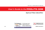
PRODIG-1+
99 Washington Street
Melrose, MA 02176
Fax 781-665-0780
TestEquipmentDepot.com
SATELLITE HUNTER
0 MI1061
USER’S MANUAL PRODIG-1+.
TABLE OF CONTENTS
1. GENERAL......................................................................................................................1
1.1 Description ..............................................................................................................1
1.2 Specifications..........................................................................................................2
2. SAFETY RULES ...........................................................................................................5
2.1 General ...................................................................................................................5
2.2 Specific Precautions ...............................................................................................7
2.3 Descriptive Examples of Over-Voltage Categories ...............................................7
4. OPERATING INSTRUCTIONS...................................................................................13
4.1 Description of the Controls and Elements ...........................................................13
4.2 Antenna Adjustment for Optimum Reception ......................................................14
4.2.1 Satellite Detection and Localisation (1> DETECT).......................................15
4.2.2 Satellite Identification (2 > IDENTIFY) ..........................................................16
4.2.3 Antenna Adjustment for Optimum Signal Quality (3> ADJUST) ..................18
4.3 Instrument Configuration ......................................................................................19
5. MAINTENANCE ..........................................................................................................21
5.1 Replacing the Battery ...........................................................................................21
5.2 Cleaning Recommendations ................................................................................22
English
3. INSTALLATION.............................................................................................................9
3.1 Power Supply..........................................................................................................9
3.1.1 Operation Using the Mains Adapter ................................................................9
3.1.2 Operation Using Batteries................................................................................9
3.1.3 Battery Charging ............................................................................................10
3.2 Installation and Start-Up.......................................................................................11
Test Equipment Depot - 800.517.8431 - 99 Washington Street Melrose, MA 02176
FAX 781.665.0780 - TestEquipmentDepot.com
USER’S MANUAL PRODIG-1+.
SATELLITE HUNTER
PRODIG-1+
1. GENERAL
1.1 Description
Because of the range of services offered by modern satellites and the ever
increasing signal density, different tests have been developed from those available in
classic satellite detectors and meters. There is a need to discern among different
satellites, to adjust the skew and to check digital signal quality.
The PRODIG-1+ responds to the need for an installation tool that might allow
making the job fast and including all necessary measurements to secure quality of
reception. Nevertheless, measurements are information that needs to be compared with
known references. Comparison takes time in order to analyse the data for each
installation.
The PRODIG-1+ has been designed to guarantee the maximum number of
installations with the best possible quality, thereby helping the installer to evaluate the
results.
The instrument directly determines if signal quality is of a sufficient level for
reception. This is done on the basis of the internal BER measurement and the signal
noise ratio (SNR).
The PRODIG-1+ processes all the information and gives to the installer just the
information he requires, thereby making his work as easy as possible.
The PRODIG-1+ is a very easy to use instrument that guides the user through 3
steps, enabling the desired satellite to be located, guaranteeing its identification and
accurately adjusting the receiver antenna to obtain the best possible signal quality.
In the PRODIG-1+, the ultimate measurement to determinate the signal quality is
the Signal/Noise ratio (SNR), this is directly related to the BER (Bit Error Rate). The
instrument displays ‘BER’ when the BER is < 2x10E-4 (equivalent to good quality) and
‘ber’ when the BER is > 2x10E-4 (equivalent to poor quality). This threshold may be
reprogrammed according to the signal quality level specified by each operator.
05/2003
Page 1
English
The arrival of Digital TV boosted the installation of Direct To Home satellite TV
systems. The continuous release of new packages or 'bouquets' and services such as
Internet, affordable connection fees and subsidised boxes require new simplified
installation procedures that are capable of guaranteeing received signal quality.
USER’S MANUAL PRODIG-1+.
The instrument is a useful tool when installing either a specific service or satellite, or
a series of services or satellites. Its specific use is determined by the instrument
programming, which in turn depends on the country or geographical area.
The PRODIG-1+ has been specially designed to stand rough working
conditions, it includes a back-light display and offers long battery life and short charging
times.
1.2 Specifications
TUNING
Frequency range
Measurement points
RF INPUT
Impedance
Connector
Level range
Maximum signal level
QPSK SIGNAL PARAMETERS
Symbol rate
Code rate
Spectral inversion
Quality level for acceptance
Initial values
Displayed information
Configuration
of measurement points
900 MHz to 2150 MHz.
16 maximum.
75 Ω.
Universal,
including
interchangeable adapter.
30 dBµV to 90 dBµV.
120 dBµV.
BNC
and
F
1000 to 30000 kbauds.
Auto and 1/2, 2/3, 3/4, 5/6, 6/7, 7/8.
Automatic.
Definable by user.
IDENTIFY : BER = 2x10⁻⁴
ADJUST : SNR = 5 dB
Satellite’s Azimuth, if it is detected.
Service name, network or bouquet, if it is
detected.
By means of serial connection to PC. (Cable
and program included).
EXTERNAL UNITS POWER
SUPPLY
Output voltage
Maximum output current
22 kHz signal
Voltage
Frequency
Through the RF input connector.
13 V, 18 V. ± 1 V.
300 mA.
Selectable.
0.6 V ± 0.2 V.
22 kHz ± 4 kHz.
BACK-LIGHT DISPLAY
On, Off.
Test Equipment Depot - 800.517.8431 - 99 Washington Street Melrose, MA 02176
Page 2
FAX 781.665.0780 - TestEquipmentDepot.com
05/2003
USER’S MANUAL PRODIG-1+.
Charger
Autonomy
Charging time
Temperature of charge
beginning between 5 and 45 °C
Mains Adapter
Maximum consumption
7.2 V 1.5 Ah Ni-MH battery.
Acoustic indication and a message on the
display.
Built-in. It disconnects the powering when the
charging process ends.
70 min. typically, powering a universal LNB and
identifying a signal continuously.
70 min. approx. starting from a complete
discharge (instrument off), within the margin of
tolerated temperatures.
Outside this margin of temperature, the charger
will not initiate the charging process. With high
ambient temperatures, the charging process will
not be carried out of continuous way since the
charger circuit has a heat-protection device that
disconnects this circuit when surpassing 45°C,
returning to connect itself when low of 40°C.
90 - 250 V/50-60 Hz/18W (included).
18 W.
English
POWER SUPPLY
Battery
Low battery indication
OPERATING ENVIRONMENTAL CONDITIONS
Up to 2000 m.
Altitude
From 5 to + 40 °C.
Temperature range
80 % (up to 31 °C),
Max. relative humidity
decreasing lineally up to 50 % at 40 °C.
MECHANICAL FEATURES
Dimensions
Weight
195 mm (W) x 101 mm (H) x 44 mm (D)
480 g
INCLUDED ACCESSORIES
AA-012
AL-101
AD-055
AD-057
CA-005
CB-075
DC-259
DC-287
RM-001
Car lighter adapter.
Mains power adapter.
“F”/H-BNC/H adapter.
“F”/H-“F”/H adapter.
Mains cord CEE-7.
Rechargeable battery Ni-MH 7.2 V, 1.5 Ah.
PRODIG-1+ carrying case.
Carrying belt.
Configuration software for PRODIG-1+
OPTIONS
OP-001-11
Rechargeable battery Lithium-ion, 7.2 V, 2.2 Ah.
(CB-074)
Test Equipment Depot - 800.517.8431 - 99 Washington Street Melrose, MA 02176
05/2003
FAX 781.665.0780 - TestEquipmentDepot.com
Page 3
USER’S MANUAL PRODIG-1+.
2. SAFETY RULES
∗
Use this equipment connected only to systems with their negative of
measurement connected to ground potential.
∗
This equipment can be used in Overvoltage Category I installations and Pollution
Degree 2 environments.
∗
When using some of the following accessories use only the specified ones to
ensure safety.
Rechargeable battery
Mains power adapter
Car lighter adapter
Mains cord
∗
Observe all specified ratings both of supply and measurement.
∗
Remember that voltages higher than 60 V DC or 30 V AC rms are dangerous.
∗
Use this instrument under the specified environmental conditions.
∗
The user is only authorised to carry out the following maintenance operations:
Battery replacement
On the Maintenance paragraph the proper instructions are given.
Any other change on the equipment should be carried out by qualified personnel.
∗
Follow the cleaning instructions described in the Maintenance paragraph.
Test Equipment Depot - 800.517.8431 - 99 Washington Street Melrose, MA 02176
05/2003
FAX 781.665.0780 - TestEquipmentDepot.com
Page 5
English
2.1 General
USER’S MANUAL PRODIG-1+.
∗
Symbols related with safety:
DIRECT CURRENT
ALTERNATING CURRENT
DIRECT AND ALTERNATING
GROUND TERMINAL
PROTECTIVE CONDUCTOR
FRAME TERMINAL
EQUIPOTENTIALITY
ON (Supply)
OFF (Supply)
DOUBLE INSULATION
(Class II Protection)
CAUTION
(Risk of electric shock)
CAUTION REFER TO MANUAL
FUSE
Test Equipment Depot - 800.517.8431 - 99 Washington Street Melrose, MA 02176
Page 6
FAX 781.665.0780 - TestEquipmentDepot.com
05/2003
USER’S MANUAL PRODIG-1+.
2.2 Specific Precautions
∗
The AL-101 mains adapter is a Class I equipment, for safety reasons plug it to a
supply line with the corresponding ground terminal.
∗
When using the AL-101 mains adapter, the negative of measurement is at
ground potential.
2.3 Descriptive Examples of Over-Voltage Categories
Low voltage installations isolated from the mains.
Cat II
Portable domestic installations.
Cat III
Fixed domestic installations.
Cat IV
Industrial installations.
English
Cat I
Test Equipment Depot - 800.517.8431 - 99 Washington Street Melrose, MA 02176
05/2003
FAX 781.665.0780 - TestEquipmentDepot.com
Page 7
USER’S MANUAL PRODIG-1+.
3. INSTALLATION
3.1 Power Supply
The PRODIG-1+ is a portable instrument powered by a rechargeable battery. The
instrument comes with a mains adapter enabling the PRODIG-1+ to be connected to
the mains for operation and battery charging.
3.1.1 Operation Using the Mains Adapter
Connect the mains adapter to the PRODIG-1+ using the external power connector
[4] (see figure 7) located on the left side panel. Connect the adapter to the mains,
thereby automatically starting the battery charging process. The instrument will emit an
acoustic indication and the information on battery charging (see ‘3.1.3 Battery
Charging’) will be shown on the display. If the battery is already charged, the instrument
will automatically disconnect. To halt the charging process, press any of the three keys
[3], see figure 6) for more than 2 s (the battery-charging
To start operation, keep any of the three instrument keys (
[1],
[2] or
[3], see figure 6) pressed down for more than 1 s. Under these conditions the
instrument starts up. Battery charging process will stop if the instrument is used during
the process.
CAUTION
Before using the mains adapter, make sure that it is the appropriate one for your mains
system: Mains power adapter model AL-101.
The mains adapter is exclusively designed for indoor use.
3.1.2 Operation Using Batteries
The instrument may be powered using a 7.2 V and 1.5 Ah Ni-MH battery
(CB-075).
For the instrument to work using the battery, you need only press any instrument
key (
[1],
[2] or
[3], see figure 6) for more than 1 s. With the battery
fully charged, the PRODIG-1+ has an approximate autonomy of 70 minutes
uninterrupted operation.
When the battery is flat, you will hear an acoustic indication, the screen will show
the message ‘BATTERY LOW’ and, afterwards, the instrument will automatically switch
off.
05/2003
Page 9
English
(
[1],
[2] or
screen will disappear).
USER’S MANUAL PRODIG-1+.
3.1.3 Battery Charging
To fully charge the battery with the PRODIG-1+ switched off, connect the mains
adapter to the external power supply input
[4] (see figure 7). Then connect the
adapter to the mains. The charging process starts automatically. The instrument will
emit an acoustic indication and the display will show the battery voltage level, the
charge percentage and how long the battery has been charging.
Figure 1.- Battery charging.
When a charging process is carried out within the allowed temperature margin with
the equipment switch off, it appears on the display the previous indications, in opposite
case is shown the message “please wait...”, and the process stops when activating the
heat-protection circuit. If after some minutes the message does not disappear from
screen, is advisable to disconnect the mains adapter for two or three minutes before
connecting it to the equipment again. The charging process would have to begin
normally.
When charging is completed, the instrument is automatically disconnected while
you hear two acoustic indications and the display will show how long the battery has
been charging. In the case of charging process stops due to heat-protection activation,
this one will be started again automatically when the internal temperature returns to the
allowed margin for a normal battery charging.
Charging time depends on the state of the battery. If the battery is very flat,
charging will be some 70 minutes (40 minutes to achieve 60% total capacity). When the
battery is fully charged, the instrument automatically disconnects.
IMPORTANT REMARK
Due to the battery technology the reading of charge percetage will not be correct until
after about 5 minutes of beginning the charging process.
IMPORTANT REMARK
When starting the battery charging process and when using the instrument for a long
period of time, a heating of the instrument can be observed. This heating is normal in
the power margin that must be dissipated, according to the battery charge status and
the LNB consumption.
Test Equipment Depot - 800.517.8431 - 99 Washington Street Melrose, MA 02176
Page 10
FAX 781.665.0780 - TestEquipmentDepot.com
05/2003
USER’S MANUAL PRODIG-1+.
3.2 Installation and Start-Up
The PRODIG-1+ satellite hunter has been designed for use as a portable
instrument.
Press any of the three keys (
[1],
[2],
[3], see figure 6) for more than
1 s and the instrument starts up in Auto Power OFF mode. In other words, the
instrument will automatically switch off if none of the keys have been pressed after 5
minutes. If you wish to cancel the automatic power off, keep the key pressed down for
more then 2 s when starting up the instrument.
On starting up, you will see the instrument presentation screen (see figure 2).
Figure 2.- Instrument presentation screen.
English
Next, a screen appears showing the name of the company and user (figure 3).
Figure 3.- Company and user name screen.
Afterwards, you see a screen saying whether the instrument automatic
disconnection is on (‘AUTO POWER OFF’) or not (‘MANUAL POWER OFF’):
Figure 4.- Automatic disconnection indicator.
Finally, you see the detection function (1> DETECT) screen.
Figure 5.- Example of detection function screen.
Test Equipment Depot - 800.517.8431 - 99 Washington Street Melrose, MA 02176
05/2003
FAX 781.665.0780 - TestEquipmentDepot.com
Page 11
USER’S MANUAL PRODIG-1+.
4. OPERATING INSTRUCTIONS
4.1 Description of the Controls and Elements
Front panel
English
Figure 6.- Front panel.
[1]
DETECT
Activates the detect function for any satellite signal, both digital and analogue.
Enables the instrument to be switched on or off.
Pressing repeatedly the key it allows to activate or deactivate the display
back-light function.
[2]
IDENTIFY
Activates the identification function to see if the detected satellite is one
already memorised by the instrument. Enables the instrument to be switched
on or off.
[3]
ADJUST
Activates the precision adjustment function in order to fine adjust the antenna
for optimum signal reception. Enables the instrument to be switched on or off.
Test Equipment Depot - 800.517.8431 - 99 Washington Street Melrose, MA 02176
05/2003
FAX 781.665.0780 - TestEquipmentDepot.com
Page 13
USER’S MANUAL PRODIG-1+.
Side panels
Figure 7.- Side panels.
[4]
External 12 V power input.
[5]
DATA. Connector for
configuration by a PC.
[6]
RF. RF signal input.
Maximum level 120 dBµV. Universal connector for F/F or F/BNC adapter,
input impedance of 75 Ω.
data
transfer, for
instrument
calibration
and
4.2 Antenna Adjustment for Optimum Reception
The PRODIG-1+ has been designed to adjust the orientation of a satellite antenna
so that it achieves the optimum reception of the digital satellite signal for a memorised
satellite.
The adjustment process consists of three steps:
1 Satellite detection and localisation: 1> DETECT
2 Identification of localised satellite: 2> IDENTIFY
3 Precise antenna adjustment for optimum signal quality. 3> ADJUST
Figure 8.- Valid sequences diagram.
Page 14
05/2003
USER’S MANUAL PRODIG-1+.
During the entire process the instrument monitors the state of the cable, the
connector and LNB. Therefore, if it detects that the noise level is below a reference
level (standard value: 100 mV), the display will show the message ‘NO LNB?’ indicating
that the LNB is not detected.
Figure 9.- DETECT function screen when no LNB is detected.
If the measured LNB power supply voltage falls 1 V below the nominal value (for
example 12 V when the nominal value is 13 V) the instrument displays the message
‘CABLE SHORT’ (short-circuit) and temporarily switches off the power source to prevent
overloads. After 3 s, it switches on the power supply again to see if the short-circuit has
disappeared.
This may occur due to a temporary fall in voltage when connecting or disconnecting
the instrument from the rest of the installation. The message may also appear when the
power supply overloads on using an LNB with excessive consumption.
This function is directly accessed on starting the instrument. If this is not the active
function, press key
[1] to select it.
The purpose of this function is to detect when the antenna is pointing to a satellite
(detection).
On connecting the instrument to the low-noise amplifier located in the antenna
focus, the passage of any radio-frequency source (the satellite) is shown by a bar-graph
and an acoustic indication. To produce this indication, the instrument measures the
energy received across the entire satellite band.
In the case of no detection, the bar remains to the left of the display. When a
satellite is detected, the bar moves to the right of the display in proportion to the power
of the detected signal.
On moving the antenna from one end to the other (for example, from east to west)
you can count the different geostationary satellites detected.
The bar indication is percentage, relative to the maximum signal level that may be
measured by the detector. So that for the same type of antenna and LNB, you will
obtain approximately the same detection value.
The bar-graph scale dynamically adapts to the maximum and minimum levels being
detected, thereby optimising the sensitivity of the bar-graph.
The screen also shows the measured value of the voltage supplied to the LNB and
displays if the 22 kHz signal is being applied (see figure 10).
05/2003
Page 15
English
4.2.1 Satellite Detection and Localisation (1> DETECT)
USER’S MANUAL PRODIG-1+.
A screen like the one below appears on the display:
Figure 10.- DETECT function screen.
If no antenna is detected, the display shows the message ‘No LNB?’ (see figure 9)
and no acoustic indication is emitted.
4.2.2 Satellite Identification (2 > IDENTIFY)
Once a satellite has been detected (by localising a power maximum), check if the
received signal corresponds to some memorised satellite. Select the memorised
satellites identification function 2> IDENTIFY by pressing key
try the different satellite detection points.
[2]. Once selected,
The identification system is based on a previously loaded satellite data table.
Consult the configuration sheet supplied with the instrument for further information on
the satellites that your instrument can detect.
The instrument can memorise up to sixteen combinations of frequencies and
polarisations (16 detection points). The number of active points (selectable) may be
configured. A greater or lesser number of satellites can be identified depending on the
number of active points and what you wish to assign to each satellite. Therefore, for
example, if you assign one frequency and the two possible polarisations to each
satellite (i.e. 2 points for each satellite) and you only activate 14 points, the instrument
will be able to identify a total of 7 different satellites. See the configuration sheet
delivered with the instrument for further information. Each detection point has a name of
up to 4 letters assigned to it, these are momentarily shown on the display when
selected (see figure 12).
Note:
You are recommended to assign two test points to each satellite, one with
vertical polarisation and another one with horizontal polarisation, to guarantee
satellite identification.
As shown in figure 11, key
[2] enables the selected detection point to be
changed sequentially. Therefore, the selected test point changes every time that you
press this key. To select a specific detection point, repeatedly press this key until the
display shows the name assigned to the required point.
Page 16
05/2003
USER’S MANUAL PRODIG-1+.
Figure 11.- Rotation of active detection points.
When you select a satellite detection point, the name (four letters maximum)
assigned to that point is momentarily displayed.
Figure 12.- Initial satellite identification screen.
If the provider does not use the field corresponding to the orbital position data, ‘0O’ will
be shown on the display.
ATTENTION
English
Afterwards, and if a signal with a valid transport stream is detected in the frequency
(or frequencies) assigned to this satellite, then the instrument shows the message ‘lock’
on the screen and attempts to obtain the orbital position of the satellite to which the
antenna is pointing to. When this information is detected, it is shown on the display.
Sometimes this may cause a reduction of the identifying text characters number.
The signal provider is the exclusive responsible of the orbital position accuracy. PROMAX
ELECTRONICA, S.A. only extracts and shows the information contained in the detected
signal.
Later, the instrument attempts to obtain the Service Provider, Network and Bouquet.
If it is not possible to determine the Service Provider, it attempts to show the Network
name. If it cannot determine that too, it will attempt to show the Bouquet. If it still has
trouble identifying the signal but detects a valid transport stream, it will show the
message “MPEG-2 ... DATA?”
Figure 13.- Identifying a memorised satellite.
You may find that the instrument does not manage to initially determine any of the
three parameters and that it shows the message “MPEG-2 ... DATA?”, to subsequently
obtain one of the previous parameters and alter the on-screen message.
If the instrument does not detect a signal with a valid transport stream, then the
‘lock’ message does not appear on the screen and it continues to show the name that
has been assigned to that satellite detection point (see figure 12).
Test Equipment Depot - 800.517.8431 - 99 Washington Street Melrose, MA 02176
05/2003
FAX 781.665.0780 - TestEquipmentDepot.com
Page 17
USER’S MANUAL PRODIG-1+.
Signal Quality
The IDENTIFY function also shows the information regarding the signal quality.
Now, when a signal with a valid transport stream is detected, the PRODIG-1+ shows
‘lock’ on the display and proceeds to measure the BER.
Once
measured
(approximately 5 s later) the ‘lock’ indication changes to ‘BER’ if the BER is < 2x10E-4
(equivalent to good quality) or ‘ber’ if the BER is > 2x10E-4 (equivalent to poor quality).
BER measurement will be repeated every 5 s.
The QPSK demodulator circuit tends to measure better as time passes due to the fact
that it includes an input signal tracking and adaptation algorithm. Therefore, to ensure a
correct signal quality reading, you are recommended to wait until a few measurements
have been taken.
Figure 14.- IDENTIFY function screen.
4.2.3 Antenna Adjustment for Optimum Signal Quality (3> ADJUST)
Once the antenna has been positioned so that it receives maximum power and
checked that it is pointing to the right satellite, you should adjust the antenna so that it
produces optimum reception quality. Press button
[3] to select the 3> ADJUST
function. This function measures the signal noise ratio SNR at the digital demodulator
output and shows the measured value on the screen both numerically (in dB) and
graphically.
Test Equipment Depot - 800.517.8431 - 99 Washington Street Melrose, MA 02176
Page 18
FAX 781.665.0780 - TestEquipmentDepot.com
05/2003
USER’S MANUAL PRODIG-1+.
22 kHz signal
Active function
indicator
The signal is applied
Measured value
of the LNB voltage
The signal is not applied
Signal indication
No signal with a valid transport
stream can be detected
snr:
SNR value in dB
Bar-graph of the SNR
Valid signal with an SNR
smaller than that defined
as threshold
SNR : Valid signal with an SNR
greater than that defined
as threshold
The top line of the screen shows the measured LNB voltage and whether the 22
kHz are present (see figure 15). It also shows whether a signal with valid transport
stream is detected at the frequency (or frequencies) assigned to a specific satellite (in
which case ‘snr’ or ‘SNR’ appears on screen).
Note:
For the final step of precise adjustment and signal quality optimisation, it is
important to select the test point where the signal is at its most critical. This
guarantees the quality of the other points with more favourable conditions.
If a signal with a valid transport stream presents a signal/noise ratio (SNR) greater
than the value internally defined by the instrument as the threshold for a good quality
signal, then the screen shows the message ‘SNR’. Otherwise, if the value is below this
threshold, the screen will show the message ‘snr’. The instrument is delivered already
configured with a quality threshold of 5 dB. This value corresponds to the DVB
recommendation for a CODE RATE = 3/4. Nevertheless, the user can alter this value to
adapt it to his own quality specification. (see section ‘4.3 Instrument Configuration’).
If, on moving the antenna, the signal noise ratio value exceeds the quality
reference, then the instrument will emit a high-pitched acoustic signal. On the other
hand, if the value is below the quality reference then the instrument emits a low-pitched
signal.
If you wish to measure the signal/noise ratio for other satellites memorised by the
instrument and you know that the antenna is correctly oriented, you can change
satellites by pressing key
[3] until you have selected the right one.
4.3 Instrument Configuration
The various parameters and information stored in the PRODIG-1+ may be modified
by entering the Service Mode and using the SH.EXE PC program. This program is
supplied with the instrument (RM-001).
05/2003
Page 19
English
Figure 15.- Measuring SNR.
USER’S MANUAL PRODIG-1+.
The instrument allows you to define the number of measuring points (up to 16), the
different parameters for each point (frequency, signal characteristics, LNB voltage, etc.)
and the text messages shown on the display, among others.
To enter the Service Mode start up the instrument by simultaneously pressing keys
[1] and
[3].
All the necessary information for configuring the instrument and using the SH.EXE
configuration and control program can be found in the manual accompanying the
program.
To switch off the instrument, as in the normal operating mode, simply press any of
the three instrument keys (
[1],
[2] or
[3]) for more than 2 s.
Test Equipment Depot - 800.517.8431 - 99 Washington Street Melrose, MA 02176
Page 20
FAX 781.665.0780 - TestEquipmentDepot.com
05/2003
USER’S MANUAL PRODIG-1+.
5. MAINTENANCE
5.1 Replacing the Battery
The battery (CB-075) should be replaced when you notice that its capacity, when
fully-charged, has fallen below 60% of its nominal value.
Replace the old battery by another CB-075 battery. The battery can be bought in
your habitual PROMAX supplier. Explosion or fire hazard can occur if other battery type
is used.
CAUTION
The battery used can present fire or chemical burn hazard if it is severely mistreat.
Do not disassembly or cremate or heat the battery above 100ªC under no
circumstances.
1. Switch off the instrument.
2. Remove the battery-compartment lid on the rear panel, by extracting the 2
retaining screws.
3. Disconnect the battery cable and the NTC sensor cable from the instrument.
4. Replace the battery with a new one.
5. Connect the battery to connector J6 next to the battery receptacle, as well as
the NTC sensor cable to connector J8 (see figure 16). Each connector has only
one position.
6. Place and secure the battery compartment lid using the 2 screws.
English
To replace the battery, please follow the process below:
CAUTION
All the components of the Ni-MH battery included in the CB-075 ensemble are
recyclable. Return as soon as possible the used battery to PROMAX ELECTRONICA
S.A. or to an authorised recycling centre of this type of batteries. If any doubt, consult
directly PROMAX ELECTRONICA,S.A.
Keep them out of the reach of the child.
If in any doubt, please contact our Customer Service Centre before undertaking any
operation.
Test Equipment Depot - 800.517.8431 - 99 Washington Street Melrose, MA 02176
05/2003
FAX 781.665.0780 - TestEquipmentDepot.com
Page 21
USER’S MANUAL PRODIG-1+.
Connector J8
Connector J6
NTC sensor black wire
Battery red wite
Battery black wire
Figure 16.- Battery receptacle.
5.2 Cleaning Recommendations
CAUTION
To clean the cover, take care the instrument is disconnected
CAUTION
Do not use scented hydrocarbons or chlorized solvents. Such products may attack the
plastics used in the construction of the cover.
The cover should be cleaned by means of a light solution of detergent and water
applied with a soft cloth.
Dry thoroughly before using the system again.
CAUTION
Do not use for the cleaning of the front panel and particularly the viewfinders, alcohol or
its derivatives, these products can attack the mechanical properties of the materials and
diminish their useful time of life.
Test Equipment Depot - 800.517.8431 - 99 Washington Street Melrose, MA 02176
Page 22
FAX 781.665.0780 - TestEquipmentDepot.com
05/2003