1
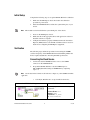
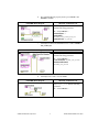
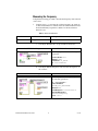
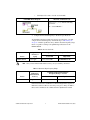
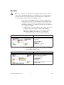
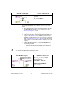
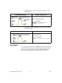
CALIBRATION PROCEDURE
NI PXIe-6674T
This document describes how to write a calibration procedure for the
10 MHz oscillator frequency of the NI PXIe-6674T timing and
synchronization modules.
Contents
Conventions ............................................................................................ 1
Software .................................................................................................. 2
Documentation ........................................................................................ 2
Calibration Interval ................................................................................. 2
Password ................................................................................................. 3
Test Equipment ....................................................................................... 3
Test Conditions ....................................................................................... 3
Calibration Procedure ............................................................................. 3
Initial Setup...................................................................................... 4
Verification ...................................................................................... 4
Connecting the Clock Source ................................................... 4
Measuring the Frequency ......................................................... 6
Adjustment....................................................................................... 8
Reverification................................................................................... 10
Where to Go for Support......................................................................... 11
Conventions
The following conventions apply to this document:
»
The » symbol leads you through nested menu items and dialog box options
to a final action. The sequence File»Page Setup»Options directs you to
pull down the File menu, select the Page Setup item, and select Options
from the last dialog box.
This icon denotes a note, which alerts you to important information.
When symbol is marked on a product, it denotes a warning advising you to
take precautions to avoid electrical shock.
When symbol is marked on a product, it denotes a component that may be
hot. Touching this component may result in bodily injury.
bold
Bold text denotes items that you must select or click in the software, such
as menu items and dialog box options. Bold text also denotes parameter
names.
italic
Italic text denotes variables, emphasis, a cross-reference, or an introduction
to a key concept. Italic text also denotes text that is a placeholder for a word
or value that you must supply.
monospace
Text in this font denotes text or characters that you should enter from the
keyboard, sections of code, programming examples, and syntax examples.
This font is also used for the proper names of disk drives, paths, directories,
programs, subprograms, subroutines, device names, functions, operations,
variables, filenames, and extensions.
Software
This calibration procedure requires NI-Sync and NI-VISA. NI-Sync and
NI-VISA support a number of application development environments
(ADEs) and programming languages, including LabVIEW,
LabWindows™/CVI™, and Microsoft Visual C++. When you install the
drivers, you need to install support for only the ADE or programming
language you are using.
Documentation
You need the NI-Sync User Manual to calibrate the NI PXIe-6674T.
The NI-Sync User Manual contains detailed information about using
the NI-Sync driver, including information about installing NI-Sync and
creating applications that use the NI-Sync driver. These sources, along with
this document, are your primary references for writing your calibration
utility. You also can refer to the documentation for the programming
language or application development environment you are using. For
further information about the device you are calibrating, refer to the
NI PXIe-6674T User Manual.
Calibration Interval
The measurement requirements of the application determine how often you
should calibrate the device to ensure its accuracy. National Instruments
recommends that you calibrate the NI PXIe-6674T yearly. You may want
to shorten this interval based on the application demands.
NI PXIe-6674T Calibration Procedure
2
ni.com
Password
The default password for password-protected operations is NI.
Test Equipment
Calibrating the NI PXIe-6674T requires the following equipment.
Equipment
Recommended Model
10 MHz clock source
Symmetricom/Datum 8040
BNC-SMA cable
PXI Express chassis
Requirements
Accurate to within
0.75 parts-per-billion (ppb)
—
—
NI PXIe-1062Q
—
Test Conditions
Follow these guidelines to optimize connections and test conditions during
the calibration procedure:
•
Install the NI PXIe-6674T in the system timing slot of the PXI Express
chassis. The calibration procedure requires features of PXI Express
that are accessible only in the system timing slot.
•
Maintain a temperature of approximately 25 °C ± 5 °C.
•
Keep relative humidity below 80 percent.
•
Use shielded copper wire for all cable connections to the device.
•
Allow a warm up time of at least three hours for the NI PXIe-6674T to
ensure the measurement circuitry is at a stable operating temperature.
•
Keep PXI Express chassis filters clean and fan speed set to High.
•
Be sure to allow for adequate warm up time for the frequency reference
used.
Calibration Procedure
The steps used in the calibration procedure are as follows:
1.
Initial setup.
2.
Verification.
3.
Adjustment.
4.
Reverification.
© National Instruments Corporation
3
NI PXIe-6674T Calibration Procedure
Initial Setup
Complete the following steps to set up the NI PXIe-6674T for calibration.
Note
1.
Make sure the PXI Express chassis involved in the calibration
procedure is powered off.
2.
Install the NI PXIe-6674T board into the system timing slot of your
chassis.
The module must be installed in the system timing slot of the chassis.
3.
Power on the PXI Express chassis.
4.
Make sure that all the appropriate driver and application software is
installed on the host computer.
5.
Configure the hardware properly with Measurement & Automation
Explorer (MAX). Refer to the NI PXIe-6674T Installation Guide for
details about configuring the PXI Express equipment.
Verification
The following steps outline the procedure for measuring the 10 MHz
oscillator frequency on the NI PXIe-6674T and determining whether the
device requires adjustment to meet the published specifications.
Connecting the Clock Source
1.
Connect the external 10 MHz reference source to the CLKIN
connector on the NI PXIe-6674T.
2.
Program the NI PXIe-6674T to route the CLKIN signal to
PXI_CLK10_IN without using its 10 MHz PLL by completing
steps a–d.
Use the data in the C function call reference as inputs to your LabVIEW VI where
applicable.
Note
a.
Call niSync Initialize VI to set up a handle for the device.
LabVIEW Block Diagram
NI-SYNC C Function Call
Call niSync_init with the following
parameters:
resourceName: Dev1
idQuery: NULL
resetDevice: VI_TRUE
vi: *SessionHandle
NI PXIe-6674T Calibration Procedure
4
ni.com
b.
Set a writable NI-Sync property node to pass FALSE to the
Use PLL? attribute.
LabVIEW Block Diagram
NI-SYNC C Function Call
Call niSync_SetAttributeViBoolean
with the following parameters:
vi: “<SessionHandle>”
terminalName: “”
attributeID:
NISYNC_ATTR_CLKIN_USE_PLL
attributeValue: VI_FALSE
c.
Call niSync Connect Clock Terminals VI to connect CLKIN to
PXI_CLK10_IN.
LabVIEW Block Diagram
NI-SYNC C Function Call
Call niSync_ConnectClkTerminals
with the following parameters:
vi: “<SessionHandle>”
sourceTerminal: NISYNC_VAL_CLKIN
destinationTerminal:
NISYNC_VAL_CLK10
d.
Call niSync Close VI to close the handle.
LabVIEW Block Diagram
NI-SYNC C Function Call
Call niSync_close with the following
parameter:
vi: “<SessionHandle>”
© National Instruments Corporation
5
NI PXIe-6674T Calibration Procedure
Measuring the Frequency
Complete the following procedure to measure the frequency of the onboard
clock source.
1.
Complete steps a–c to measure the oscillator frequency. To obtain an
accurate measurement for calibration, the measurement duration must
be made sufficiently long. Refer to Table 1 for the measurement
duration to use.
Table 1. Measurement Duration
Device
NI PXIe-6674T
Measure Accuracy
Required Measurement Duration
0.5 ppb
a.
20 seconds
Call niSync Initialize VI to set up a handle for the device.
LabVIEW Block Diagram
NI-SYNC C Function Call
Call niSync_init with the following
parameters:
resourceName: Dev1
idQuery: NULL
resetDevice: VI_FALSE
vi: *SessionHandle
b.
Call niSync Measure Frequency VI to measure the frequency of
the oscillator.
LabVIEW Block Diagram
NI-SYNC C Function Call
Call niSync_MeasureFrequency with
the following parameters:
vi: “<SessionHandle>”
sourceTerminal:
NISYNC_VAL_OSCILLATOR
duration: 20
actualDuration: *actualDuration
measuredFrequency:
*measuredFrequency
error: *error
NI PXIe-6674T Calibration Procedure
6
ni.com
c.
Call niSync Close VI to close the session handle.
LabVIEW Block Diagram
NI-SYNC C Function Call
Call niSync_close with the following
parameter:
vi: “<SessionHandle>”
2.
Compare the measured frequency to the device specifications.
To determine if the device under test meets its specifications, you must
compare the measured frequency obtained in step 1 of Measuring the
Frequency with the specified accuracy. Table 2 shows the frequency range
that is acceptable according to the published specifications for the
NI PXIe-6674T.
Table 2. One Year Test Limits
Device
NI PXIe-6674T
Note
Specified
Accuracy +
Aging
± 56.5 ppb
Acceptable Frequency Range—As Found
Low Limit
9,999,999.435 Hz
High Limit
10,000,000.565 Hz
One year test limits include initial accuracy, one year stability, and retrace.
Table 3. Adjustment Target Frequency Ranges
Device
NI PXIe-6674T
Calibration
Measurement
Accuracy
0.5 ppb
Calibration Measurement Target
Frequency Range—As Left
Low Limit
High Limit
9,999,999.995 Hz
10,000,000.005 Hz
If the measured value is within the low-limit and high-limit range listed
under the Calibration Measurement Target Frequency Range in Table 3,
the board is considered to be calibrated and no adjustment is needed.
© National Instruments Corporation
7
NI PXIe-6674T Calibration Procedure
Adjustment
Use of a binary search algorithm is recommended to find the optimal oscillator
control voltage. The NI PXIe-6674T uses a 16 bit digital-to-analog converter (DAC) to
create the oscillator control voltage, therefore at most 16 iterations of adjusting and
measuring would be needed to calibrate the 10 MHz oscillator.
Note
If the accuracy of the 10 MHz oscillator is outside the specified range
for the product, the device is out of calibration. A programmable voltage
controls the oscillator frequency. By varying this voltage and precisely
measuring the frequency, you can find a voltage that gives a frequency as
close as possible to 10 MHz.
1.
Complete steps a–c to set the oscillator control voltage. The range of
acceptable voltage values is 0.0 V to 4.095 V with frequency
increasing as voltage increases. Use a control voltage of 2.0475 V,
which is in the middle of the valid range, as a starting point.
a.
Call niSync Initialize VI to set up a handle for the device.
LabVIEW Block Diagram
NI-SYNC C Function Call
Call niSync_init with the following
parameters:
resourceName: Dev1
idQuery: NULL
resetDevice: VI_FALSE
vi: *SessionHandle
b.
Set a writable NI-Sync property node to pass the constant 2.0475
to the Oscillator Voltage attribute.
LabVIEW Block Diagram
NI-SYNC C Function Call
Call niSync_SetAttributeViBoolean
with the following parameters:
vi: “<SessionHandle>”
terminalName: “”
attributeID:
NISYNC_ATTR_OSCILLATOR_VOLTAGE
attributeValue: 2.0475
NI PXIe-6674T Calibration Procedure
8
ni.com
c.
Call niSync Close VI to close the session handle.
LabVIEW Block Diagram
NI-SYNC C Function Call
Call niSync_close with the following
parameter:
vi: “<SessionHandle>”
Proceed with the following steps to find the correct oscillator control
voltage.
2.
After setting the control voltage, measure the frequency again with
the NI-Sync Measure Frequency VI, as shown in step 1 of the
Measuring the Frequency section.
3.
Compare the measured frequency to the device specifications.
4.
If the measured frequency is still outside of the specified limit, repeat
steps 1–3 of the Adjustment section until the measured value falls
within the acceptable frequency range for your module, as shown in
Table 3, Adjustment Target Frequency Ranges. Adjust the oscillator
control voltage up to increase the frequency and down to decrease the
frequency.
5.
Commit the calibration values to the Calibration EEPROM using
the following procedure.
a.
Call niSync Initialize External Calibration VI to initialize the
process.
NI is the default user password. If you have changed the calibration password, use
your user-selected calibration password in place of NI.
Note
LabVIEW Block Diagram
NI-SYNC C Function Call
Call niSync_InitExtCal with the
following parameters:
resourceName: “<MAX ID>”
password: NI
calibrationInstrumentHandle:
*SessionHandle
© National Instruments Corporation
9
NI PXIe-6674T Calibration Procedure
b.
Call niSync Adjust Oscillator Voltage VI to adjust the voltage of
the oscillator.
LabVIEW Block Diagram
NI-SYNC C Function Call
Call
niSync_CalAdjustOscillatorVoltage
with the following parameters:
vi: “<SessionHandle>”
newVoltage: <new control voltage>
oldVoltage: *oldVoltage
c.
Call niSync Close External Calibration VI to commit the settings
and close the session.
LabVIEW Block Diagram
NI-SYNC C Function Call
Call niSync_CloseExtCal with the
following parameter:
vi: “<SessionHandle>”
action: NISYNC_VAL_EXT_CAL_COMMIT
Reverification
After completing the adjustments to the NI PXIe-6674T, it is important that
you verify the oscillator frequency operation by repeating the steps listed
in the Verification section. Re-verifying after making the adjustments
ensures that the NI PXIe-6674T is operating within its test limits.
NI PXIe-6674T Calibration Procedure
10
ni.com
Where to Go for Support
The National Instruments Web site is your complete resource for technical
support. At ni.com/support you have access to everything from
troubleshooting and application development self-help resources to email
and phone assistance from NI Application Engineers.
National Instruments corporate headquarters is located at
11500 North Mopac Expressway, Austin, Texas, 78759-3504.
National Instruments also has offices located around the world to help
address your support needs. For telephone support in the United States,
create your service request at ni.com/support and follow the calling
instructions or dial 512 795 8248. For telephone support outside the United
States, contact your local branch office:
Australia 1800 300 800, Austria 43 662 457990-0,
Belgium 32 (0) 2 757 0020, Brazil 55 11 3262 3599,
Canada 800 433 3488, China 86 21 5050 9800,
Czech Republic 420 224 235 774, Denmark 45 45 76 26 00,
Finland 358 (0) 9 725 72511, France 01 57 66 24 24,
Germany 49 89 7413130, India 91 80 41190000, Israel 972 3 6393737,
Italy 39 02 41309277, Japan 0120-527196, Korea 82 02 3451 3400,
Lebanon 961 (0) 1 33 28 28, Malaysia 1800 887710,
Mexico 01 800 010 0793, Netherlands 31 (0) 348 433 466,
New Zealand 0800 553 322, Norway 47 (0) 66 90 76 60,
Poland 48 22 328 90 10, Portugal 351 210 311 210,
Russia 7 495 783 6851, Singapore 1800 226 5886,
Slovenia 386 3 425 42 00, South Africa 27 0 11 805 8197,
Spain 34 91 640 0085, Sweden 46 (0) 8 587 895 00,
Switzerland 41 56 2005151, Taiwan 886 02 2377 2222,
Thailand 662 278 6777, Turkey 90 212 279 3031,
United Kingdom 44 (0) 1635 523545
CVI, LabVIEW, National Instruments, NI, ni.com, the National Instruments corporate logo, and the
Eagle logo are trademarks of National Instruments Corporation. Refer to the Trademark Information at
ni.com/trademarks for other National Instruments trademarks. The mark LabWindows is used
under a license from Microsoft Corporation. Windows is a registered trademark of Microsoft
Corporation in the United States and other countries. Other product and company names mentioned
herein are trademarks or trade names of their respective companies. For patents covering
National Instruments products/technology, refer to the appropriate location: Help»Patents in your
software, the patents.txt file on your media, or the National Instruments Patent Notice at
ni.com/patents.
© 2010 National Instruments Corporation. All rights reserved.
373090A-01
Sep10