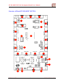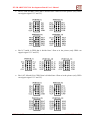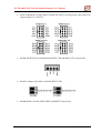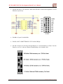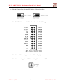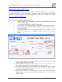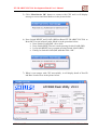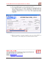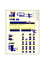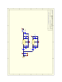
1
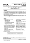
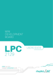
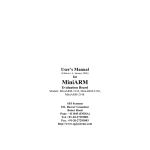
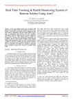
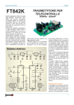
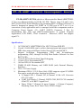
ET-JR ARM7 LPC2214 Development Board User's Manual ET-JR ARM7 LPC2214 Development Board ET-JR ARM7 LPC2214 which is a Microcontroller Board ARM7TDMIS Core uses Microcontroller 16/32-Bit 144 PIN. There’s many I/O and it uses MCU No.LPC2214 from PHILIPS to be permanent MCU on Board. Structure of board is designed to arrange I/O PORT as 10 PIN type of ETT, so it is so convenient to truly application and it is arranged with basic components such as Connector Power Supply +5V, UART (RS232) Connector 2 Port for downloading Hex File and RS232communication of written Program Application, LCD PORT, JTAG Connector. Moreover, GPIO can support signal 5V. Specifications 1. 2. 3. 4. 5. 6. 7. 8. 9. 16/32-Bit MCU ARM7TDMI-S No.LPC2214 from PHILIPS Crystal 19.6608 MHz can be collect data maximum high speed 58.9824 MHz when using with Phase-Locked Loop (PLL) internal MCU Support In-System Programming (ISP) and In-Application programming (IAP) through On-Chip Boot-Loader Software via Port RS232-CH0 1 Port JTAG 20 Pin for Real Time Debugging 1 Port LCD 14 Pin standard ETT 16 Port GPIO 10 Pin standard ETT 256KB FLASH Memory and 16KB RAM (with External Memory Interface) VIN +5V Power Supply Maximum GPIO 112 I/O Pins (Only GPIO supports signal 5V)GPIO Pins can be used with other functions as follows; • 2 Channel SPI, 1 Channel I2C, 8-Channel 10 Bit A/D Converter (0V-3.3V only) • UART Full Duplex 2 Channel; RS232-CH0, RS232-CH1 standard 4 Pin ETT to be RS232 signal level • Timer 32-Bit 2 Channel (4 input Capture / 4 Output Compare), Watchdog Timer, Real Time Clock, PWM 6 Output ETT CO.,LTD. -1- WWW.ETT.CO.TH ET-JR ARM7 LPC2214 Development Board User's Manual Structure of Board ET-JR ARM7 LPC2214 1 3 2 16 18 15 4 17 19 14 5 21 20 13 6 22 12 7 10 11 9 8 23 24 25 29 ETT CO.,LTD. 28 27 -2- 26 WWW.ETT.CO.TH ET-JR ARM7 LPC2214 Development Board User's Manual • No. 6, 3, 14 and 10 is GPIO that is divided into 4 Ports as in the picture (only GPIO can support signal 3.3V and 5V). • No. 2, 7 and 9 is GPIO that is divided into 3 Port as in the picture (only GPIO can support signal 3.3V and 5V). • No. 1, 17, 13 and 12 is GPIO2 that is divided into 4 Port as in the picture (only GPIO can support signal 3.3V and 5V). ETT CO.,LTD. -3- WWW.ETT.CO.TH ET-JR ARM7 LPC2214 Development Board User's Manual • No. 4, 5, 8 and 11 is GPIO3 that is divided into 4 Port as in the picture (only GPIO can support signal 3.3V and 5V). • No. 24 and 25 is Port Communication RS232-CH0 and RS232-CH1 respectively. • No. 23 is Jumper for Enable or Disable RS232-CH1. • No.18 and 19 is Switch LOAD (BSL) and RESET respectively. ETT CO.,LTD. -4- WWW.ETT.CO.TH ET-JR ARM7 LPC2214 Development Board User's Manual • No. 15 and 16 is LCD Connector 14PIN and VR10K to contrast the brightness of LCD Monitor respectively. • No. 20 is Crystal 19.6608 MHz. • No. 21 is MCU ARM7TDMI-S LPC2214 from Philips. • No. 22 is Jumper for selecting internal Memory or external Memory to Boot. For this Board, we set as 11 that use internal Flash Memory to be default value. ETT CO.,LTD. -5- WWW.ETT.CO.TH ET-JR ARM7 LPC2214 Development Board User's Manual • No. 26 is Jumper for selecting RUN Mode or Debugging Mode. • No. 27 is JTAG Connector 20PIN to Interface with JTAG Debugger. • No. 28 is red LED to display operation of Power Supply. • No. 29 is connecting point of +5V Power Supply for board and GND. ETT CO.,LTD. -6- WWW.ETT.CO.TH ET-JR ARM7 LPC2214 Development Board User's Manual Download Hex File into MCU of Board To download Hex file into Flash memory of MCU internal Board, we use program LPC2000 Flash utility V2.3.3 from Philips. It connects with MCU through Serial Port of computer PC and we can download this program free without any charge from website www.semiconductors.philips.com Procedure to Download Hex File into MCU 1. Interface Cable RS232 from RS232 Serial Port Communication of PC with Board (RS232-CH0) 2. Set Jumper RUN/DEB to be on RUN Mode side 3. Power Supply +5V into Board and see red LED (PWR) must be status ON 4. Run Program LPC2000 Flash Utility of Philips and it will display results as in the picture below 5. Start setting default values of Program into Board ET-JR ARM7 LPC2214 from ETT; in this case, user should set default values as in the picture below; 1) Must select Com Port to be corresponding with Com Port number that is truly usage (in this example uses COM1) 2) Set Baud Rate between 4800 - 38400 (these values are tested, so user can use them without any problem)or using standard speed that is 9600 3) We can not select MCU in Device blank because program will display number of LPC2214 by self (depend on permanent MCU of board) when it can be connected with Board successfully. 4) Set Crystal Oscillator to be corresponding with truly usage internal Board with KHz unit and not use greater than 5 digits. In this case, we set it as 19.6608 MHz or 19660. ETT CO.,LTD. -7- WWW.ETT.CO.TH ET-JR ARM7 LPC2214 Development Board User's Manual 5) Click “Read device ID” button to connect with CPU and it will display message to access into Boot Mode as in the picture below. 6) Press Switch RESET and LOAD (BSL)on Board ET-JR ARM7 LPC2214 to Reset MCU to run in Boot Loader Mode as in the procedure below; Press Switch LOAD (BSL) for a while Press Switch RESET but we remain pressing Switch LOAD (BSL) Let Switch RESET but we remain pressing Switch LOAD (BSL) Finally, let Switch LOAD (BSL)and then click “OK” 7) When it can connect with CPU successfully, it will display detail of Part ID and Boot Loader ID as in the picture below. ETT CO.,LTD. -8- WWW.ETT.CO.TH ET-JR ARM7 LPC2214 Development Board User's Manual 8) Then select HEX File that we want programming into MCU 9) Click “Upload to Flash” and program LPC2000 starts downloading data into MCU instantly. We can see Status “Uploading to LPC2000 RAM and Copying to Flash Memory” as in the picture below. We must wait for this proceeding completely and we can see Status “File Upload Successfully Completed” 10) When the operation of program completely, must press Switch RESET on Board and MCU starts running follow downloaded program instantly. ----------------------------------------------------------------------------------------------------------------- ETT CO., LTD 1112/96-98 Sukhumvit Rd., Phrakanong, Bangkok 10110 THAILAND Tel : (662) 712-1120 Fax : (662) 3917216 E-Mail : [email protected] Website : www.ett.co.th, www.etteam.com ETT CO.,LTD. -9- WWW.ETT.CO.TH A B C D P3.0 P3.2 P3.4 P3.6 +3V3 P2.0 P2.2 P2.4 P2.6 +3V3 P1.16 P1.18 P1.20 P1.22 +3V3 P0.0 P0.2 P0.4 P0.6 +3V3 1 1 2 4 6 8 10 2 4 6 8 10 2 4 6 8 10 1 3 5 7 9 2 4 6 8 10 CN17 P3.0-P3.7 1 3 5 7 9 CN13 P2.0-P2.7 1 3 5 7 9 CN10 P1.16-P1.23 1 3 5 7 9 CN6 P0.0-P0.7 JP1 TRST TDI TMS TCK RTCK TDO RST# DEB/RUN R3 100K P3.1 P3.3 P3.5 P3.7 GND P2.1 P2.3 P2.5 P2.7 GND P1.17 P1.19 P1.21 P1.23 GND P0.1 P0.3 P0.5 P0.7 GND R6 10K R2 100K R5 100K P3.8 P3.10 P3.12 P3.14 +3V3 P2.8 P2.10 P2.12 P2.14 +3V3 P1.24 RTCK TDI TMS +3V3 P0.8 P0.10 P0.12 P0.14 +3V3 R7 100K R4 100K 2 4 6 8 10 2 4 6 8 10 2 4 6 8 10 1 3 5 7 9 2 2 4 6 8 10 CN18 P3.8-P3.15 1 3 5 7 9 CN14 P2.8-P2.15 1 3 5 7 9 CN2 2 4 6 8 10 12 14 16 18 20 P3.9 P3.11 P3.13 P3.15 GND P2.9 P2.11 P2.13 P2.15 GND P1.25 TDO TCK TRST GND P0.9 P0.11 P0.13 P0.15 GND JTAG 1 3 5 7 9 11 13 15 17 19 CN11 P1.24-P1.31 1 3 5 7 9 CN7 P0.8-P0.15 +3V3 2 P3.16 P3.18 P3.20 P3.22 +3V3 P2.16 P2.18 P2.20 P2.22 +3V3 +3V3 P1.0 P0.16 P0.18 P0.20 P0.22 +3V3 2 4 6 8 10 2 4 6 8 10 2 4 6 8 10 1 3 5 7 9 3 2 4 6 8 10 CN19 P3.16-P3.23 1 3 5 7 9 CN15 P2.16-P2.23 1 3 5 7 9 CN12 P1.0-P1.1 1 3 5 7 9 CN8 P0.16-P0.23 P2.5 P2.7 P2.0 P2.1 3 +V RS EN D1 D3 D5 D7 P3.17 P3.19 P3.21 P3.23 GND P2.17 P2.19 P2.21 P2.23 GND GND P1.1 P0.17 P0.19 P0.21 P0.23 GND +5V 1 3 5 7 9 11 13 2 4 6 8 10 12 14 P3.24 P3.26 P3.28 P3.30 +3V3 P2.24 P2.26 P2.28 P2.30 +3V3 P0.28 P0.30 +3V3 P0.24 CLCD CN3 P2.4 P2.6 P2.2 2 4 6 8 10 2 4 6 8 10 1 3 5 7 9 2 4 6 8 10 CN20 P3.24-P3.31 1 3 5 7 9 CN16 P2.24-P2.31 1 3 5 7 9 CN9 P0.24-P0.30 GND VO RW D0 D2 D4 D6 VR1 10K 4 4 P3.25 P3.27 P3.29 P3.31 GND P2.25 P2.27 P2.29 P2.31 GND GND P0.25 P0.27 P0.29 19.6608MHz C17 22pF X1 RST# P3.0 P3.1 P3.2 P3.3 P3.4 P3.5 P3.6 P3.7 P3.8 P3.9 P3.10 P3.11 P3.12 P3.13 P3.14 P3.15 P3.16 P3.17 P3.18 P3.19 P3.20 P3.21 P3.22 P3.23 P3.24 P3.25 P3.26 P3.27 P3.28 P3.29 P3.30 P3.31 P2.0 P2.1 P2.2 P2.3 P2.4 P2.5 P2.6 P2.7 P2.8 P2.9 P2.10 P2.11 P2.12 P2.13 P2.14 P2.15 P2.16 P2.17 P2.18 P2.19 P2.20 P2.21 P2.22 P2.23 P2.24 P2.25 P2.26 P2.27 P2.28 P2.29 P2.30 P2.31 C18 22pF 141 142 135 22 89 88 87 81 80 74 73 72 71 66 65 64 63 62 56 55 53 48 47 46 45 44 41 40 36 35 30 29 28 27 97 96 98 105 106 108 109 114 115 116 117 118 120 124 125 127 129 130 131 132 133 134 136 137 1 10 11 12 13 16 17 18 19 20 ARM7TDMI-S 5 Philips LPC2214 P2.0/D0 P0.0/TXD0/PWM1 P2.1/D1 P0.1/RXD0/PWM3/EINT0 P2.2/D2 P0.2/SCL/CAP0.0 P2.3/D3 P0.3/SDA/MAT0.0/EINT1 P2.4/D4 P0.4/SCK0/CAP0.1 P2.5/D5 P0.5/MISO0/MAT0.1 P2.6/D6 P0.6/MOSI0/CAP0.2 P2.7/D7 P0.7/SSEL0/PWM2/EINT2 P2.8/D8 P0.8/TXD1/PWM4 P2.9/D9 P0.9/RXD1/PWM6/EINT3 P2.10/D10 P0.10/RTS1/CAP1.0 P2.11/D11 P0.11/CTS1/CAP1.1 P2.12/D12 P0.12/DSR1/MAT1.0 P2.13/D13 P0.13/DTR1/MAT1.1 P2.14/D14 P0.14/DCD1/EINT1 P2.15/D15 P0.15/RI1/EINT2 P2.16/D16 P0.16/EINT0/MAT0.2/CAP0.2 P2.17/D17 P0.17/CAP1.2/SCK1/MAT1.2 P2.18/D18 P0.18/CAP1.3/MISO1/MAT1.3 P2.19/D19 P0.19/MAT1.2/MOSI1/CAP1.2 P2.20/D20 P0.20/MAT1.3/SSEL1/EINT3 P2.21/D21 P0.21/PWM5/CAP1.3 P2.22/D22 P0.22/CAP0.0/MAT0.0 P2.23/D23 P0.23 P2.24/D24 P0.24 P2.25/D25 P0.25 P2.26/D26/BOOT0 P0.27/AIN0/CAP0.1/MAT0.1 P2.27/D27/BOOT1 P0.28/AIN1/CAP0.2/MAT0.2 P2.28/D28 P0.29/AIN2/CAP0.3/MAT0.3 P2.29/D29 P0.30/AIN3/EINT3/CAP0.0 P2.30/D30/AIN4 P2.31/D31/AIN5 P1.0/CS0 P1.1/OE P1.16/TRACEPKT0 P1.17/TRACEPKT1 P1.18/TRACEPKT2 P1.19/TRACEPKT3 P1.20/TRACESYNC P3.0/A0 P1.21/PIPESTAT0 P3.1/A1 P1.22/PIPESTAT1 P3.2/A2 P1.23/PIPESTAT2 P3.3/A3 P1.24/TRACECLK P3.4/A4 P1.25/EXTIN0 P3.5/A5 P1.26/RTCK P3.6/A6 P1.27/TDO P3.7/A7 P1.28/TDI P3.8/A8 P1.29/TCK P3.9/A9 P1.30/TMS P3.10/A10 P1.31/TRST P3.11/A11 P3.12/A12 V3 P3.13/A13 V3 P3.14/A14 V3 P3.15/A15 V3 P3.16/A16 V3 P3.17/A17 V3 P3.18/A18 V3 P3.19/A19 V3 P3.20/A20 V3 P3.21/A21 V3 P3.22/A22 V3A P3.23/A23/XCLK P3.24/CS3 V18A P3.25/CS2 V18 P3.26/CS1 V18 P3.27/WE P3.28/BLS3/AIN7 VSS P3.29/BLS2/AIN6 VSS P3.30/BLS1 VSS P3.31/BLS0 VSS VSS NC VSS VSS RESET VSS VSS VSS XTAL1 VSS VSS VSSA XTAL2 VSSA_PLL U4 5 6 6 3 9 26 38 54 67 79 93 103 107 111 128 139 138 143 110 37 +1V8 P1.0 P1.1 P1.16 P1.17 P1.18 P1.19 P1.20 P1.21 P1.22 P1.23 P1.24 P1.25 RTCK TDO TDI TCK TMS TRST +3V3 91 90 34 24 15 7 102 95 86 82 70 60 52 144 140 126 113 43 2 31 39 51 57 77 94 104 112 119 14 P0.0 P0.1 P0.2 P0.3 P0.4 P0.5 P0.6 P0.7 P0.8 P0.9 P0.10 P0.11 P0.12 P0.13 P0.14 P0.15 P0.16 P0.17 P0.18 P0.19 P0.20 P0.21 P0.22 P0.23 P0.24 P0.25 P0.27 P0.28 P0.29 P0.30 42 49 50 58 59 61 68 69 75 76 78 83 84 85 92 99 100 101 121 122 123 4 5 6 8 21 23 25 32 33 C16 0.1uF C15 0.1uF 12 11 9 10 5 4 3 1 ENA/DIS Date: File: A3 Size Title JP3 RXD1 JP2 TXD1 RXD1 TXD1 P0.1 P0.0 C11 0.1uF C9 0.1uF JP5 BOOT 0 P2.26 1 P2.27 00 01 10 11 +3V3 R12 10K Select 8-bit memory on CS0 for boot. Select 16-bit memory on CS0 for boot. Select 32-bit memory on CS0 for boot. Select Internal Flash memory. Select Memory for Boot JP4 +3V3 C13 0.1uF S1 RESET RST# R8 22K C12 0.1uF C10 0.1uF R11 10K +3V3 13 14 8 7 15 6 2 7 1 2 3 4 CN4 RS232-CH0 1 2 3 4 CN5 RS232-CH1 R10 1K S2 LOAD(BSL) P0.14 R9 22K +5V +5V 8 WWW.ETT.CO.TH 1.0 8 ETT CO., LTD. Revision ET-ARM7 LPC2214 Development Board (ETT CO., LTD.) 0 1 C14 0.1uF R1I T1O R2I T2O GND V- V+ 16 +3V3 19-May-2006 Sheet of D:\ARM Project\LPC2214\Schematics\LPC2214.Ddb Drawn By: Number P0.9 P0.8 R1O T1I R2O T2I C2- C2+ C1- VCC U5 ICL3232 C1+ 7 A B C D A B C D 1 1 +5V 1 2 CN1 +5V ZD1 5V6 2 C5 10uF/16V D2 1N5819 C1 100uF/16V D1 1N5819 2 C6 0.1uF Vin U3 LD1117S18 C2 0.1uF Vin U1 LD1086-3V3 GND GND C7 10uF/16V Vout C3 100uF/16V Vout +1V8 C8 0.1uF 560 R1 C4 0.1uF 3 3 LED1 +3V3(RED) Date: File: A4 Size Title L1 +3V3 FERRITE BEAD WWW.ETT.CO.TH 4 19-May-2006 Sheet of D:\ARM Project\LPC2214\Schematics\LPC2214.Ddb Drawn By: Number 1.0 ETT CO., LTD. Revision Power Supply for ET-ARM7 LPC2214 (ETT CO., LTD.) 4 A B C D