1
INTEGRAL
SPECTROMETER
SI I
SPI-MU-0-1062V3-CNES
Issue
: 5
Revision : 0
Date
: 28/02/02
Page No. : ANX8-2
PSD FM User Manual
SPI-MU-423-4215-CESR
Edition 2, Revision 0 (19/2/2001)
Author : J. Knödlseder
1. SCOPE OF THE DOCUMENT
The purpose of this document is to provide a user manual for the PSD FM subassembly. This manual
should introduce the user in the general functionality of the system, and should provide a reference
document that allows for a proper configuration and usage of the system.
2. REFERENCE DOCUMENTS
RD1
FM software version 227 / V1.07
RD2
PSD Software description, SPI-NT-4232-4194-CESR, Ed. 2, Rev. 0, 06/04/00
RD3
SPI INTERFACES SPECIFICATION, SPI-SI-0-1324-CNES, Issue 4, Rev. 0, 07/01/00
RD4
Spectrometer User Manual, SPI-MU-0-1062-CNES, Issue 4, Rev. 0, 10/11/00
3. GENERAL FUNCTIONALITY
The scope of this paragraph is the presentation of the general functionality of the PSD subassembly in
order to clarify the meaning of the PSD parameters.
3.1. Multiplexing
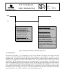
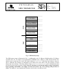
The PSD subassembly is equipped with 19 input channels (also called MUX channels), each connected to
one of the 19 fast detector output channels. Each of the 19 channels can be enabled or disabled
individually in order to activate or to suppress pulse-shape discrimination for individual detectors. A
disabled MUX channel neither generates FET triggers (see section 3.2), nor does it add to the sum of
detector currents provided to the A/D converters (see section 3.3).
Pulse Shape Discrimination for background reduction is only meaningful for events that are contained
within one germanium detector. Therefore it has been decided to have only one PSD system that treats all
19 detectors with an input multiplexing. If signals occur on several PSD inputs, the event is considered as
a multi-detector event and it will not be treated by the PSD sub-assembly (see section 3.2).