1
INTEGRAL
SPECTROMETER
SI I
SPI-MU-0-1062V3-CNES
Issue
: 5
Revision : 0
Date
: 28/02/02
Page No. : ANX8-3
3.2. Triggering
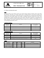
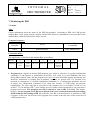
The PSD sub-assembly has its own triggering electronics that triggers the analysis of the Germanium
detector currents. The hardware trigger (or front-end trigger) is characterised by four parameters: the
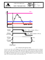
FRONT END TRIGGER LEVEL (FET), the LOWER LEVEL DISCRIMINATOR (LLD), the
TIME WINDOW (TW), and the UPPER LEVEL DISCRIMINATOR (ULD). The first 3 quantities
(FET, LLD, TW) are configurable by telecommand while the ULD is a fixed level. The major aim of the
hardware threshold is to trigger the PSD system on detector pulses and to separate real event triggers from
noise triggers. Consequently, the optimum trigger parameters will depend on the noise in the system The
front-end trigger parameters are the most critical parameters of the PSD system since noise triggers can
easily exceed the expected event rates, leading directly to an exceed in time-tag rates sent to DFEE.
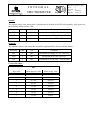
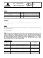
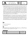
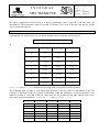
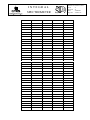
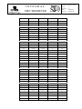
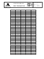
Each of the 19 input channels (MUX channels) has a front-end trigger threshold that is set by the FET
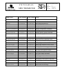
parameter. Note that the FET setting is common to all 19 detector channels, although the conversion
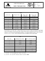
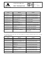
curve between trigger threshold and parameter setting is different for each of the 19 channels. This
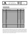
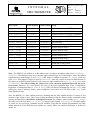
implies that a given FET setting results in different FET threshold levels (see conversion table in section
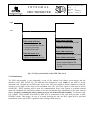
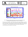
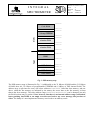
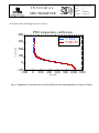
4.2). The FET (or MUX) trigger defines the start of a PSD event (see Fig. 1).
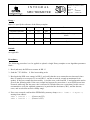
The analogue signal of the 19 MUX channels is summed and distributed to the A/D converters (see
section 3.3) and the LLD and ULD threshold comparators. This means that the LLD and ULD levels are
common to all 19 channels, and possible variations in the threshold level among the 19 channels only
arise due to possible variations in the amplification gains of the pre-amplifiers of the 19 MUX channels.