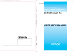
Download CJ-series PROFINET I/O Controller Unit Operation Manual for
Transcript
Cat. No. W511-E2-01 ZX-T Series Controller Machine Automation CJ-series CJ-Series PROFINET I/O Controller Unit for NJ-Series CPU Unit OPERATION MANUAL Authorized Distributor: Cat. No. W511-E2-01 Note: Specifications subject to change without notice. PROFINET I/O Controller Unit Operation Manual for NJ-series CPU Unit CJ1W-PNT21 PROFINET I/O Controller Unit Printed in Europe W511-E2-01 Introduction Introduction Thank you for purchasing a CJ-series CJ1W-PNT21 IO Controller Unit. This manual contains information that is necessary to use the CJ-series CJ1W-PNT21 IO Controller Unit for an NJ-series CPU Unit. Please read this manual and make sure you understand the functionality and performance of the NJ-series CPU Unit before you attempt to use it in a control system. Keep this manual in a safe place where it will be available for reference during operation. Intended Audience This manual is intended for the following personnel, who must also have knowledge of electrical systems (an electrical engineer or the equivalent). • Personnel in charge of introducing FA systems. • Personnel in charge of designing FA systems. • Personnel in charge of installing and maintaining FA systems. • Personnel in charge of managing FA systems and facilities. For programming, this manual is intended for personnel who understand the programming language specifications in international standard IEC 61131-3 or Japanese standard JIS B3503. Applicable Products This manual covers the following products. CJ-series CJ1W-PNT21 IO Controller Unit CJ-series PROFINET IO Controller Unit Operation Manual for NJ-series CPU Unit (W511) 1 Introduction Relevant Manuals There are three manuals that provide basic information on the NJ-series CPU Units: the NJ-series CPU Unit Hardware User’s Manual, the NJ-series CPU Unit Software User’s Manual and the NJ-series Instructions Reference Manual. Most operations are performed from the Sysmac Studio Automation Software. Refer to the Sysmac Studio Version 1 Operation Manual (Cat. No. W504) for information on the Sysmac Studio. Other manuals are necessary for specific system configurations and applications. Read all of the manuals that are relevant to your system configuration and application to make the most of the NJ-series CPU Unit. NJ-series User’s Manuals CJ-series Special Unit Operation Manuals for NJ-series CPU Unit NJ-series Troubleshooting Manual NJ-series CPU Unit Built-in EtherNet/IP Port User´s Manual NJ-series Motion Control Instructions Reference Manual NJ-series CPU Unit Built-in EtherCAT Port User´s Manual NJ-series CPU Unit Motion Control User´s Manual NJ-series Instructions Reference Manual NJ-series CPU Unit Software User´s Manual NJ-series CPU Unit Hardware User´s Manual Basic information Introduction to NJ-series Controllers Setting devices and hardware Using motion control Using EtherCAT Using EtherNet/IP Using CJ-series Units Software settings Using motion control Using EtherCAT Using EtherNet/IP Programming Using motion control Using EtherCAT Using CJ-series Units Programming error processing Testing operation and debugging Using motion control Using EtherCAT Using EtherNet/IP Troubleshooting and managing errors in an NJ-series Controller Use the relevant manuals for references according to any error that occurs. Maintenance Using EtherCAT Using EtherNet/IP Using CJ-series Units 2 CJ-series PROFINET IO Controller Unit Operation Manual for NJ-series CPU Unit (W511) Introduction Manual Configuration NJ-series CPU Unit Hardware User’s Manual (Cat. No. W500) Section Description Section 1 Introduction This section provides an introduction to the NJ-series Controllers and their features, and gives the NJ-series Controller specifications. Section 2 System Configuration This section describes the system configuration used for NJ-series Controllers. Section 3 Configuration Units This section describes the parts and functions of the configuration devices in the NJseries Controller configuration, including the CPU Unit and Configuration Units. Section 4 Installation and Wiring This section describes where and how to install the CPU Unit and Configuration Units and how to wire them. Section 5 Troubleshooting This section describes the event codes, error confirmation methods, and corrections for errors that can occur. Section 6 Inspection and Maintenance This section describes the contents of periodic inspections, the service life of the Battery and Power Supply Units, and replacement methods for the Battery and Power Supply Units. Appendices The appendices provide the specifications of the Basic I/O Units, Unit dimensions, load short-circuit protection detection, line disconnection detection, and measures for EMC Directives. NJ-series CPU Unit Software User’s Manual (Cat. No. W501) Section Description Section 1 Introduction This section provides an introduction to the NJ-series Controllers and their features, and gives the NJ-series Controller specifications. Section 2 CPU Unit Operation This section describes the variables and control systems of the CPU Unit and CPU Unit status. Section 3 I/O Ports, Slave Configuration, and Unit Configuration This section describes how to use I/O ports, how to create the slave configuration and unit configuration and how to assign functions. Section 4 Controller Setup This section describes the initial settings of the function modules. Section 5 Designing Tasks This section describes the task system and types of tasks. Section 6 Programming This section describes programming, including the programming languages and the variables and instructions that are used in programming. Section 7 Simulation, Transferring Projects to the Physical CPU Unit, and Operation This section describes simulation of Controller operation and how to use the results of simulation. Section 8 CPU Unit Status This section describes CPU Unit status. Section 9 CPU Unit Functions This section describes the functionality provided by the CPU Unit. Section 10 Communications Setup This section describes how to go online with the CPU Unit and how to connect to other devices. Section 11 Example of Actual Application Procedures This section describes the procedures that are used to actually operate an NJ-series Controller. Section 12 Troubleshooting This section describes the event codes, error confirmation methods, and corrections for errors that can occur. Appendices The appendices provide the CPU Unit specifications, task execution times, systemdefined variable lists, data attribute lists, CJ-series Unit memory information, CJseries Unit memory allocation methods, and data type conversion information. CJ-series PROFINET IO Controller Unit Operation Manual for NJ-series CPU Unit (W511) 3 Introduction Sysmac Studio Version 1 Operation Manual (Cat. No. W504) Section Description Section 1 Introduction This section provides an overview and lists the specifications of the Sysmac Studio and describes its features and components. Section 2 Installation and Uninstallation This section describes how to install and uninstall the Sysmac Studio. Section 3 System Design This section describes the basic concepts for designing an NJ-series System with the Sysmac Studio and the basic operating procedures. Section 4 Programming This section describes how to create programs with the Sysmac Studio. Section 5 Online Connections to a Controller This section describes how to go online with a Controller. Section 6 Debugging This section describes how to debug the programs online on the Controller or debug it offline with the Simulator. Section 7 Other Functions This section describes Sysmac Studio functions other than system design functions. Section 8 Reusing Programming This section describes how to reuse the programs that you create with the Sysmac Studio. Section 9 Support Software Provided with the Sysmac Studio This section describes the Support Software that is provided with the Sysmac Studio. Section 10 Troubleshooting This section describes the error messages that are displayed when you check a program on the Sysmac Studio and how to correct those errors. Appendices The appendices describe the following: Driver Installation for Direct USB Cable Connection Specifying One of Multiple Ethernet Interface Cards Online Help Simulation Instructions CJ-series PROFINET IO Controller Unit Operation Manual for NJseries CPU Unit (W511) (This Manual) 4 Section Description Section 1 Features and System Configuration This section provides an introductory overview of PROFINET, its functions and how to configure a system. It also addresses the PROFINET IO Controller Unit’s features and specifications. Section 2 Nomenclature and Installation This section describes the nomenclature and installation of the PROFINET IO Controller Unit. Section 3 Configuration Software This section presents an overview of the configuration software and gives insight in the main aspects of defining a PROFINET IO configuration. Section 4 Data Exchange with the CPU Unit This section describes the words allocated to the PROFINET IO Controller Unit in the CIO Area and DM Area. These words both enable controlling the Unit and accessing Unit and network status. Section 5 Operation This section describes how to operate the CJ1W-PNT21 PROFINET IO Controller Unit in a Network. It will discuss setting up a network, configuring all the connected devices and starting the network. Furthermore, it provides information the I/O data exchange performance and it also provides information on how to monitor a network using the Unit and CX-ConfiguratorFDT. Section 6 Message Communications This section describes message communications using commands sent from the user program in the CPU Unit. Section 7 Troubleshooting and Maintenance This section describes error processing, periodic maintenance operations, and troubleshooting procedures needed to keep the PROFINET network operating properly. We recommend reading through the error processing procedures before operation so that operating errors can be identified and corrected quickly. Appendices --- CJ-series PROFINET IO Controller Unit Operation Manual for NJ-series CPU Unit (W511) Introduction SmartSlice GRT1-Series PROFINET IO Communication Unit Operation Manual (W13E) Section Description Section 1 Features and Specifications This section provides an introductory overview of the GRT1 series SmartSlice I/O Units and the GRT1-PNT PROFINET IO Communication Unit, its functions and how to set up and configure it for a PROFINET network. Section 2 Installation and Wiring This section shows the GRT1-series PROFINET IO Communication Unit and identifies its controls and indicators. It contains the procedures for installing and wiring the Communication Unit as well as the GRT1- series SmartSlice I/O Units. It also contains the procedures for setting up the PROFINET IO network. Section 3 Setup and Operation This section describes the operational aspects of the GRT1-PNT and the SmartSlice I/O System. It first discusses the operational features which can be used, prior to describing how to set up the system and how to operate and monitor it on a PROFINET IO network. Section 4 Troubleshooting and Maintenance This section describes the troubleshooting procedures and maintenance operations for the PROFINET IO Communication Unit, needed to keep the PROFINET IO network working optimally. Appendices --- SmartSlice GRT1-Series Slice I/O Units Operation Manual (Cat. No. W455) Section Description Section 1 Available Units and Features This section describes the features of GRT1-series Slice I/O Units and lists the available Units. Section 2 Shared Specifications and Functions This section describes the specifications and functions that are shared by all of the Slice I/O Units. Section 3 Installation and Wiring This section provides information on installing and wiring the Slice I/O Units. Section 4 Digital I/O Units This section provides the specifications and shows the components, terminal arrangements, wiring diagrams and dimensions for the Digital I/O Units. Section 5 Analog I/O Units This section provides the information required to operate Analog Input Units and Analog Output Units. Section 6 Temperature Input Units This section provides the information required to operate Temperature Input Units. Section 7 Counter Units and Positioning Unit This section provides the information required to operate Counter Units and the Positioning Unit. Section 8 Other Units This section provides the basic specifications for the other Units used in Slice I/O terminals. Section 9 Troubleshooting This section describes error processing and troubleshooting procedures needed to keep the Slice I/O Units operating properly. Appendices The appendices describe the following: Explicit Messages Standard Models Power Consumption and Weight Tables I/O Current Consumption Table Precautions When Connecting Two-wire DC Sensors CJ-series PROFINET IO Controller Unit Operation Manual for NJ-series CPU Unit (W511) 5 Introduction CJ1W-PNT21 PROFINET IO Controller Units Operation Manual (Cat. No. W12E) Section 6 Description Section 1 Precautions The information contained in this section is important for the safe and reliable operation of the CJ1W-PNT21 PROFINET IO Controller Unit. You must read this section and understand the information contained before attempting to set up or operate a CJ1W-PNT21 PROFINET IO Controller Unit and related systems. Section 2 Features and Specifications This section provides an introductory overview of the CJ1W-PNT21 PROFINET IO Controller for the CJ-Series, its functions and how to set up and configure it for a PROFINET IO network. Section 3 Installation and Wiring This section shows the CJ1-series PROFINET IO Controller Unit and identifies the controls and indicators of the Unit. This section also contains the procedures for installing and wiring the CJ1W-PNT21 Unit, in addition to the procedures for setting up the PROFINET IO network. Section 4 Configuration Software This section presents an overview of the Configuration software and gives insight in the main aspects of defining a PROFINET IO configuration. Section 5 Allocated CIO and DM Words This section describes the words allocated to the CJ1W-PNT21 PROFINET IO Controller Unit in the CIO and DM Areas. These words facilitate controlling the Unit and accessing the Unit and network statuses. Section 6 FINS Commands and Responses This section describes the FINS message service communications commands concept as well as the commands supported by the CJ1W-PNT21 PROFINET IO Controller Units. Section 7 Operation This section describes how to operate the CJ1W-PNT21 PROFNET IO Controller Unit in a Network. It will discuss setting up a network, configuring all the connected devices and starting the network. Furthermore, it provides information the I/O data exchange performance and it also provides information on how to monitor a network, using the Unit and CXConfiguratorFDT. Section 8 Troubleshooting and Maintenance This section describes the troubleshooting procedures and maintenance operations for the PROFINET IO Communication Unit, needed to keep the PROFINET IO network working optimal. We recommend reading through the error processing procedures before operation so that operating errors can be identified and corrected more quickly. Appendices --- CJ-series PROFINET IO Controller Unit Operation Manual for NJ-series CPU Unit (W511) Introduction Manual Structure Page Structure The following page structure is used in this manual. Mounting Units Level 1 heading Level 2 heading Level 3 heading Connecting Controller Components Gives the current headings. 4 Installation and Wiring Level 2 heading 4-3 Level 3 heading 4-3-1 The Units that make up an NJ-series Controller can be connected simply by pressing the Units together and locking the sliders by moving them toward the back of the Units. The End Cover is connected in the same way to the Unit on the far right side of the Controller. A step in a procedure 1 Join the Units so that the connectors fit exactly. Hook Indicates a procedure. Hook holes Connector 4-3 Mounting Units 4 The yellow sliders at the top and bottom of each Unit lock the Units together. Move the sliders toward the back of the Units as shown below until they click into place. Move the sliders toward the back until they lock into place. Lock Release Slider Gives the number of the main section. Precautions for Correct Use Special information The sliders on the tops and bottoms of the Powe r Supply Unit, CPU Unit, I/O Units, Special I/O Units, and CPU Bus Units must be completely locked (until they click into place) after connecting the adjacent Unit connectors. Icons indicate precautions, additional information, or reference information. Manual name 4-3-1 Connecting Controller Components 2 Page tab NJ-series CPU Unit Hardware User’s Manual (W500) 4-9 This illustration is provided only as a sample. It may not literally appear in this manual. Special Information Special information in this manual is classified as follows: Precautions for Safe Use Precautions on what to do and what not to do to ensure safe usage of the product. Precautions for Correct Use Precautions on what to do and what not to do to ensure proper operation and performance. Additional Information Additional information to read as required. This information is provided to increase understanding or make operation easier. Note References are provided to more detailed or related information. CJ-series PROFINET IO Controller Unit Operation Manual for NJ-series CPU Unit (W511) 7 Introduction Precaution on Terminology In this manual, “download” refers to transferring data from the Sysmac Studio to the physical Controller and “upload” refers to transferring data from the physical Controller to the Sysmac Studio. In this manual, the CJ1W-PNT21 Unit may be referred to as “PROFINET IO Controller Unit”, “Master Unit, “IO Controller Unit”, “IO Controller” or “PNT21 Unit”. 8 CJ-series PROFINET IO Controller Unit Operation Manual for NJ-series CPU Unit (W511) Introduction Sections in this Manual 1 1 I Features and System Configuration 2 3 2 Nomenclature and Installation 3 Configuration Software 4 Data Exchange with the CPU Unit 5 Operation 6 4 5 6 7 A Message Communications I 7 Troubleshooting and Maintenance A Appendices I Index CJ-series PROFINET IO Controller Unit Operation Manual for NJ-series CPU Unit (W511) 9 CONTENTS Introduction .............................................................................................................. 1 Relevant Manuals ..................................................................................................... 2 Manual Configuration .............................................................................................. 3 Manual Structure ...................................................................................................... 7 Sections in this Manual ........................................................................................... 9 CONTENTS .............................................................................................................. 10 Read and Understand this Manual ....................................................................... 14 Safety Precautions ................................................................................................. 17 Precautions for Correct Use .................................................................................. 28 Regulations and Standards ................................................................................... 31 Unit Versions .......................................................................................................... 33 Related Manuals ..................................................................................................... 35 Revision History ..................................................................................................... 36 Section 1 1-1 Features and System Configuration Overview of PROFINET .......................................................................................................... 1-2 1-1-1 1-1-2 1-1-3 1-1-4 1-2 PROFINET IO Controller Unit ................................................................................................. 1-8 1-2-1 1-2-2 1-3 Section 2 Unit Components .................................................................................................................... 2-2 Nomenclature and Functions ..................................................................................................... 2-2 Switch settings ........................................................................................................................... 2-4 Installing the PROFINET IO Controller Unit ......................................................................... 2-7 2-2-1 2-2-2 2-2-3 10 Configuring the PROFINET IO Controller Unit ......................................................................... 1-13 PROFINET IO Controller Unit Startup Procedure .................................................................... 1-14 Nomenclature and Installation 2-1-1 2-1-2 2-2 Overview .................................................................................................................................. 1-10 Specifications ........................................................................................................................... 1-11 Basic Operating Procedures ............................................................................................... 1-13 1-4-1 1-4-2 2-1 Unit Specifications ...................................................................................................................... 1-8 Protocol Specifications ............................................................................................................... 1-9 CX-ConfiguratorFDT ............................................................................................................. 1-10 1-3-1 1-3-2 1-4 PROFINET IO Controller Unit Features ..................................................................................... 1-2 PROFINET Communication ....................................................................................................... 1-3 PROFINET Distributed I/O ......................................................................................................... 1-4 Provider/Consumer Model ......................................................................................................... 1-6 System Configuration Precautions ............................................................................................. 2-7 Mounting .................................................................................................................................... 2-7 Handling Precautions ................................................................................................................. 2-8 CJ-series PROFINET IO Controller Unit Operation Manual for NJ-series CPU Unit (W511) 2-2-4 2-3 Network Installation .............................................................................................................. 2-10 2-3-1 2-3-2 2-3-3 Section 3 3-1 CX-ConfiguratorFDT ............................................................................................................... 3-2 Starting CX-ConfiguratorFDT ..................................................................................................... 3-2 Installation Procedure for a DTM ............................................................................................... 3-3 Establishing the PROFINET IO Network ................................................................................... 3-4 CX-ConfiguratorFDT Main Window ....................................................................................... 3-5 3-2-1 3-2-2 3-2-3 3-2-4 3-2-5 3-2-6 3-3 MRP Ring Redundancy ........................................................................................................... 2-13 PROFINET IO Controller redundancy ..................................................................................... 2-14 Network and Controller Redundancy ....................................................................................... 2-15 Configuration Software 3-1-1 3-1-2 3-1-3 3-2 External Dimensions .................................................................................................................. 2-9 Device Catalog .......................................................................................................................... 3-8 Adding Devices to the Network .................................................................................................3-11 Saving and Opening Projects .................................................................................................. 3-12 Exporting to HTML ................................................................................................................... 3-12 Error Logging and FDT Monitoring .......................................................................................... 3-13 Access Control and User Management ................................................................................... 3-14 PROFINET IO Controller DTM .............................................................................................. 3-18 3-3-1 3-3-2 3-3-3 3-3-4 DTM User Interface ................................................................................................................. 3-18 PROFINET Identification ......................................................................................................... 3-20 Configuration ........................................................................................................................... 3-21 Diagnosis ................................................................................................................................. 3-28 3-4 Firmware Upgrade ................................................................................................................ 3-31 3-5 Generic IO Device DTM ........................................................................................................ 3-32 3-5-1 3-5-2 3-5-3 Section 4 4-1 Data Exchange with the CPU Unit Data Exchange with the CPU Unit ......................................................................................... 4-2 4-1-1 4-1-2 4-2 Section 5 Configuring a Network ........................................................................................................... 5-2 Adding Devices to the Network .................................................................................................. 5-3 Setting IO Device Names .......................................................................................................... 5-5 Configuring the IO Devices ................................................................................................... 5-7 5-2-1 5-3 Software Switches ..................................................................................................................... 4-8 Unit Status ................................................................................................................................. 4-9 IO Controller Status 1 ...............................................................................................................4-11 IO Device Status ...................................................................................................................... 4-13 IO Device Input Valid Flags ..................................................................................................... 4-14 IO Device New Alarms Flags ................................................................................................... 4-15 Operation 5-1-1 5-1-2 5-2 Data Flow ................................................................................................................................... 4-2 Accessing From the User Program ............................................................................................ 4-4 Device Variables for CJ-series Unit (Software Switches, Statuses) .................................. 4-8 4-2-1 4-2-2 4-2-3 4-2-4 4-2-5 4-2-6 5-1 GSDML File Support ................................................................................................................ 3-32 Installing GSDML Files ............................................................................................................ 3-33 Configuration User Interface .................................................................................................... 3-33 Defining the I/O Configuration ................................................................................................... 5-7 Configuring the IO Controller ................................................................................................ 5-9 5-3-1 5-3-2 5-3-3 5-3-4 PLC Setup ................................................................................................................................. 5-9 IO Controller Setup .................................................................................................................. 5-10 IO Device Setup ........................................................................................................................5-11 IO Device Area ........................................................................................................................ 5-12 CJ-series PROFINET IO Controller Unit Operation Manual for NJ-series CPU Unit (W511) 11 5-3-5 5-3-6 Mapping I/O Data ..................................................................................................................... 5-13 Supported Data Types and Conversion ................................................................................... 5-21 5-4 Performance .......................................................................................................................... 5-25 5-5 Operating the Network ......................................................................................................... 5-27 5-5-1 5-5-2 Section 6 6-1 User Access to the Network ..................................................................................................... 5-27 Changing the Output Data State of the IO Controller ............................................................... 5-27 Message Communications Overview .................................................................................................................................. 6-2 6-3-1 6-3-2 6-3-3 6-3-4 EXPLICIT MESSAGE SEND (2801) .......................................................................................... 6-7 MEMORY AREA READ (0101) ................................................................................................ 6-10 ERROR LOG READ (2102) ..................................................................................................... 6-11 ERROR LOG CLEAR (2103) ................................................................................................... 6-13 6-2 Sending Acyclic Messages Using SendCmd Instructions ................................................. 6-3 6-3 Acyclic Messages ................................................................................................................... 6-7 6-4 Command Message Routing ............................................................................................... 6-14 Section 7 7-1 Troubleshooting and Maintenance Troubleshooting with the PROFINET IO Controller Unit Indicators ................................... 7-2 7-1-1 7-1-2 7-2 Troubleshooting the Network ................................................................................................ 7-8 7-2-1 7-2-2 7-2-3 7-3 Troubleshooting Parameter Download ....................................................................................... 7-8 Troubleshooting the Network using CX-ConfiguratorFDT .......................................................... 7-9 CPU Unit’s ERR/ALM Indicator Lit or Flashing ........................................................................ 7-13 Event Logs ............................................................................................................................ 7-14 7-3-1 7-3-2 7-3-3 7-4 Determining Operating Status from the Indicators ..................................................................... 7-2 Troubleshooting Errors Occurring in the PROFINET IO Controller Unit .................................... 7-3 Overview of the Event Logs ..................................................................................................... 7-14 Error Table ................................................................................................................................ 7-14 Error Descriptions .................................................................................................................... 7-16 Maintenance and Replacement ........................................................................................... 7-21 7-4-1 7-4-2 7-4-3 7-4-4 Cleaning ................................................................................................................................... 7-21 Inspection ................................................................................................................................. 7-21 Replacing Faulty Units ............................................................................................................. 7-22 Addition/Replacement of Units on the PROFINET Network .................................................... 7-23 Appendices A-1 Differences in Available Functions Depending on the CPU Unit (NJ/CJ-series) to be Connected ...............................................................................................................................A-2 A-1-1 A-1-2 Differences in Available Functions .............................................................................................A-2 Differences in Accessing from the User Program ......................................................................A-2 A-2 PROFINET IO Alarm Messages .............................................................................................A-7 A-2-1 A-2-2 Introduction ................................................................................................................................A-7 Alarm Messages ........................................................................................................................A-7 Index 12 CJ-series PROFINET IO Controller Unit Operation Manual for NJ-series CPU Unit (W511) CJ-series PROFINET IO Controller Unit Operation Manual for NJ-series CPU Unit (W511) 13 Read and Understand this Manual Please read and understand this manual before using the product. Please consult your OMRON representative if you have any questions or comments. Warranty and Limitations of Liability WARRANTY OMRON's exclusive warranty is that the products are free from defects in materials and workmanship for a period of one year (or other period if specified) from date of sale by OMRON. OMRON MAKES NO WARRANTY OR REPRESENTATION, EXPRESS OR IMPLIED, REGARDING NONINFRINGEMENT, MERCHANTABILITY, OR FITNESS FOR PARTICULAR PURPOSE OF THE PRODUCTS. ANY BUYER OR USER ACKNOWLEDGES THAT THE BUYER OR USER ALONE HAS DETERMINED THAT THE PRODUCTS WILL SUITABLY MEET THE REQUIREMENTS OF THEIR INTENDED USE. OMRON DISCLAIMS ALL OTHER WARRANTIES, EXPRESS OR IMPLIED. LIMITATIONS OF LIABILITY OMRON SHALL NOT BE RESPONSIBLE FOR SPECIAL, INDIRECT, OR CONSEQUENTIAL DAMAGES, LOSS OF PROFITS OR COMMERCIAL LOSS IN ANY WAY CONNECTED WITH THE PRODUCTS, WHETHER SUCH CLAIM IS BASED ON CONTRACT, WARRANTY, NEGLIGENCE, OR STRICT LIABILITY. In no event shall the responsibility of OMRON for any act exceed the individual price of the product on which liability is asserted. IN NO EVENT SHALL OMRON BE RESPONSIBLE FOR WARRANTY, REPAIR, OR OTHER CLAIMS REGARDING THE PRODUCTS UNLESS OMRON'S ANALYSIS CONFIRMS THAT THE PRODUCTS WERE PROPERLY HANDLED, STORED, INSTALLED, AND MAINTAINED AND NOT SUBJECT TO CONTAMINATION, ABUSE, MISUSE, OR INAPPROPRIATE MODIFICATION OR REPAIR. 14 CJ-series PROFINET IO Controller Unit Operation Manual for NJ-series CPU Unit (W511) Application Considerations SUITABILITY FOR USE OMRON shall not be responsible for conformity with any standards, codes, or regulations that apply to the combination of products in the customer's application or use of the products. At the customer's request, OMRON will provide applicable third party certification documents identifying ratings and limitations of use that apply to the products. This information by itself is not sufficient for a complete determination of the suitability of the products in combination with the end product, machine, system, or other application or use. The following are some examples of applications for which particular attention must be given. This is not intended to be an exhaustive list of all possible uses of the products, nor is it intended to imply that the uses listed may be suitable for the products: • Outdoor use, uses involving potential chemical contamination or electrical interference, or conditions or uses not described in this manual. • Nuclear energy control systems, combustion systems, railroad systems, aviation systems, medical equipment, amusement machines, vehicles, safety equipment, and installations subject to separate industry or government regulations. • Systems, machines, and equipment that could present a risk to life or property. Please know and observe all prohibitions of use applicable to the products. NEVER USE THE PRODUCTS FOR AN APPLICATION INVOLVING SERIOUS RISK TO LIFE OR PROPERTY WITHOUT ENSURING THAT THE SYSTEM AS A WHOLE HAS BEEN DESIGNED TO ADDRESS THE RISKS, AND THAT THE OMRON PRODUCTS ARE PROPERLY RATED AND INSTALLED FOR THE INTENDED USE WITHIN THE OVERALL EQUIPMENT OR SYSTEM. PROGRAMMABLE PRODUCTS OMRON shall not be responsible for the user's programming of a programmable product, or any consequence thereof. CJ-series PROFINET IO Controller Unit Operation Manual for NJ-series CPU Unit (W511) 15 Disclaimers CHANGE IN SPECIFICATIONS Product specifications and accessories may be changed at any time based on improvements and other reasons. It is our practice to change model numbers when published ratings or features are changed, or when significant construction changes are made. However, some specifications of the products may be changed without any notice. When in doubt, special model numbers may be assigned to fix or establish key specifications for your application on your request. Please consult with your OMRON representative at any time to confirm actual specifications of purchased products. DIMENSIONS AND WEIGHTS Dimensions and weights are nominal and are not to be used for manufacturing purposes, even when tolerances are shown. PERFORMANCE DATA Performance data given in this manual is provided as a guide for the user in determining suitability and does not constitute a warranty. It may represent the result of OMRON's test conditions, and the users must correlate it to actual application requirements. Actual performance is subject to the OMRON Warranty and Limitations of Liability. ERRORS AND OMISSIONS The information in this manual has been carefully checked and is believed to be accurate; however, no responsibility is assumed for clerical, typographical, or proofreading errors, or omissions. 16 CJ-series PROFINET IO Controller Unit Operation Manual for NJ-series CPU Unit (W511) Safety Precautions Definition of Precautionary Information The following notation is used in this manual to provide precautions required to ensure safe usage of an NJ-series Controller. The safety precautions that are provided are extremely important to safety. Always read and heed the information provided in all safety precautions. The following notation is used. WARNING Caution Indicates a potentially hazardous situation which, if not avoided, could result in death or serious injury. Additionally, there may be severe property damage. Indicates a potentially hazardous situation which, if not avoided, may result in minor or moderate injury, or property damage. Precautions for Safe Use Indicates precautions on what to do and what not to do to ensure safe usage of the product. Precautions for Correct Use Indicates precautions on what to do and what not to do to ensure proper operation and performance. CJ-series PROFINET IO Controller Unit Operation Manual for NJ-series CPU Unit (W511) 17 Symbols The circle and slash symbol indicates operations that you must not do. The specific operation is shown in the circle and explained in text. This example indicates prohibiting disassembly. The triangle symbol indicates precautions (including warnings). The specific operation is shown in the triangle and explained in text. This example indicates a precaution for electric shock. The triangle symbol indicates precautions (including warnings). The specific operation is shown in the triangle and explained in text. This example indicates a general precaution. The filled circle symbol indicates operations that you must do. The specific operation is shown in the circle and explained in text. This example shows a general precaution for something that you must do. 18 CJ-series PROFINET IO Controller Unit Operation Manual for NJ-series CPU Unit (W511) WARNING During Power Supply Do not touch any of the terminals or terminal blocks while the power is being supplied. Doing so may result in electric shock. Do not attempt to take any Unit apart. In particular, high-voltage parts are present in the Power Supply Unit while power is supplied or immediately after power is turned OFF. Touching any of these parts may result in electric shock. There are sharp parts inside the Unit that may cause injury. Fail-safe Measures Provide safety measures in external circuits to ensure safety in the system if an abnormality occurs due to malfunction of the CPU Unit, other Units, or slaves or due to other external factors affecting operation. Not doing so may result in serious accidents due to incorrect operation. Emergency stop circuits, interlock circuits, limit circuits, and similar safety measures must be provided in external control circuits. The Controller outputs may remain ON or OFF due to deposition or burning of the output relays or destruction of the output transistors. As a countermeasure for such problems, external safety measures must be provided to ensure safe operation of the system. The CPU Unit will turn OFF all outputs from Basic Output Units in the following cases. • • • • • If an error occurs in the power supply If the power supply connection becomes faulty If a CPU watchdog timer error or CPU reset occurs If a major fault level Controller error occurs While the CPU Unit is on standby until RUN mode is entered after the power is turned ON External safety measures must be provided to ensure safe operation of the system even if the outputs turn OFF. If external power supplies for slaves or other devices are overloaded or short-circuited, the voltage will drop, outputs will turn OFF, and the system may be unable to read inputs. Provide external safety measures in controls with monitoring of external power supply voltage as required so that the system operates safely in such a case. CJ-series PROFINET IO Controller Unit Operation Manual for NJ-series CPU Unit (W511) 19 WARNING Fail-safe Measures Unintended outputs may occur when an error occurs in variable memory or in memory used for CJ-series Units. As a countermeasure for such problems, external safety measures must be provided to ensure safe operation of the system. Provide measures in the communications system and user program to ensure safety in the overall system even if errors or malfunctions occur in data link communications or remote I/O communications. If there is interference in remote I/O communications or if a major fault level error occurs, output status will depend on the products that are used. Confirm the operation that will occur when there is interference in communications or a major fault level error, and implement safety measures. Correctly set all of the EtherCAT slaves. The NJ-series Controller continues normal operation for a certain period of time when a momentary power interruption occurs. This means that the NJseries Controller may receive incorrect signals from external devices that are also affected by the power interruption. Accordingly, take suitable actions, such as external fail-safe measures and interlock conditions, to monitor the power supply voltage of the external device as required. You must take fail-safe measures to ensure safety in the event of incorrect, missing, or abnormal signals caused by broken signal lines, momentary power interruptions, or other causes. Not doing so may result in serious accidents due to incorrect operation. Voltage and Current Inputs Make sure that the voltages and currents that are input to the Units and slaves are within the specified ranges. Inputting voltages or currents that are outside of the specified ranges may cause accidents or fire. Downloading Always confirm safety at the destination before you transfer a user program, configuration data, setup data, device variables, or values in memory used for CJ-series Units from the Sysmac Studio. The devices or machines may perform unexpected operation regardless of the operating mode of the CPU Unit. 20 CJ-series PROFINET IO Controller Unit Operation Manual for NJ-series CPU Unit (W511) Caution Application Do not touch any Unit when power is being supplied or immediately after the power supply is turned OFF. Doing so may result in burn injury. Wiring Be sure that all terminal screws and cable connector screws are tightened to the torque specified in the relevant manuals. The loose screws may result in fire or malfunction. Online Editing Execute online editing only after confirming that no adverse effects will be caused by deviations in the timing of I/O. If you perform online editing, the task execution time may exceed the task period, I/O may not be refreshed with external devices, input signals may not be read, and output timing may change. CJ-series PROFINET IO Controller Unit Operation Manual for NJ-series CPU Unit (W511) 21 Precautions for Safe Use Disassembly and Dropping • Do not attempt to disassemble, repair, or modify any Units. Doing so may result in malfunction or fire. • Do not drop any Unit or subject it to abnormal vibration or shock. Doing so may result in Unit malfunction or burning. Mounting • The sliders on the tops and bottoms of the Power Supply Unit, CPU Unit, I/O Units, Special I/O Unit, and CPU Bus Units must be completely locked (until they click into place) after connecting the adjacent Unit connectors. Installation • Always connect to a ground of 100 or less when installing the Units. A ground of 100 or less must be installed when shorting the GR and LG terminals on the Power Supply Unit. Wiring • Follow the instructions in this manual to correctly perform wiring. Double-check all wiring and switch settings before turning ON the power supply. • Use crimp terminals for wiring. Do not connect bare stranded wires directly to terminals. • Do not pull on the cables or bend the cables beyond their natural limit. Do not place heavy objects on top of the cables or other wiring lines. Doing so may break the cables. • Mount terminal blocks and connectors only after checking the mounting location carefully. • Be sure that the terminal blocks, expansion cables, and other items with locking devices are properly locked into place. • Always remove any dustproof labels that are on the top of the Units when they are shipped before you turn ON the power supply. If the labels are not removed, heat will accumulate and malfunctions may occur. • Before you connect a computer to the CPU Unit, disconnect the power supply plug of the computer from the AC outlet. Also, if the computer has an FG terminal, make the connections so that the FG terminal has the same electrical potential as the FG (GR) terminal on the Power Supply Unit. A difference in electric potential between the computer and Controller may cause failure or malfunction. • If the external power supply to an Output Unit or slave has polarity, connect it with the correct polarity. If the polarity is reversed, current may flow in the reverse direction and damage the connected devices regardless of the operation of the Controller. Power Supply Design • Do not exceed the rated supply capacity of the Power Supply Units in the NJ-series Controller. The rated supply capacities are given in the NJ-series CPU Unit Hardware User’s Manual (Cat. No. W500). If the capacity is exceeded, operation may stop, malfunctions may occur, or data may not be backed up normally for power interruptions. Use NJ-series Power Supply Units for both the NJ-series CPU Rack and Expansion Racks. Operation is not possible if a CJ-series Power Supply Unit is used with an NJ-series CPU Unit or an NJ-series Power Supply Unit is used with a CJ-series CPU Unit. 22 CJ-series PROFINET IO Controller Unit Operation Manual for NJ-series CPU Unit (W511) • Do not apply voltages or connect loads to the Output Units or slaves in excess of the maximum ratings. • Surge current occurs when the power supply is turned ON. When selecting fuses or breakers for external circuits, consider the above precaution and allow sufficient margin in shut-off performance. Refer to the relevant manuals for surge current specifications. Refer to the NJ-series CPU Unit Hardware User’s Manual (Cat. No. W500) for surge current specifications. • If the full dielectric strength voltage is applied or turned OFF using the switch on the tester, the generated impulse voltage may damage the Power Supply Unit. Use the adjustment on the tester to gradually increase and decrease the voltage. • Apply the voltage between the Power Supply Unit's L1 or L2 terminal and the GR terminal when testing insulation and dielectric strength. You do not have to disconnect the LG and GR terminals to perform these tests. • Do not supply AC power from an inverter or other device with a square-wave output. Internal temperature rise may result in smoking or burning. Always input a sinusoidal wave with the frequency that is given in the NJ-series CPU Unit Hardware User’s Manual (Cat. No. W500). • Install external breakers and take other safety measures against short-circuiting in external wiring. Turning ON the Power Supply • It takes up to approximately 10 to 20 s to enter RUN mode after the power is turned ON. During that time, outputs will be OFF or will be the values specified in the Unit or slave settings, and external communications cannot be performed. Use the RUN output on the Power Supply Unit, for example, to implement fail-safe circuits so that external devices do not operate incorrectly. • Configure the external circuits so that the power supply to the control system turns ON only after the power supply to the Controller has turned ON. If the power supply to the Controller is turned ON after the control power supply, temporary errors may result in incorrect control system signals because the output terminals on Output Units may momentarily turn ON when power supply is turned ON to the Controller. Actual Operation • Check the user program, data, and parameter settings for proper execution before you use them for actual operation. Turning OFF the Power Supply • Never turn OFF the power supply to the Controller when the BUSY indicator is flashing. While the BUSY indicator is lit, the user program and settings in the CPU Unit are being backed up in the builtin non-volatile memory. This data will not be backed up correctly if the power supply is turned OFF. Also, a major fault level Controller error will occur the next time you start operation, and operation will stop. • Do not turn OFF the power supply or remove the SD Memory Card while SD Memory Card access is in progress (i.e., while the SD BUSY indicator flashes). Data may become corrupted, and the Controller will not operate correctly if it uses corrupted data. To remove the SD Memory Card from the CPU Unit while the power supply is ON, press the SD Memory Card power supply switch and wait for the SD BUSY indicator to turn OFF before you remove the SD Memory Card. • Do not disconnect the cable or turn OFF the power supply to the Controller when downloading data or the user program from Support Software. • Always turn OFF the power supply to the Controller before you attempt any of the following. • Mounting or removing I/O Units or the CPU Unit • Assembling the Units • Setting DIP switches or rotary switches • Connecting cables or wiring the system • Connecting or disconnecting the connectors CJ-series PROFINET IO Controller Unit Operation Manual for NJ-series CPU Unit (W511) 23 The Power Supply Unit may continue to supply power to the rest of the Controller for a few seconds after the power supply turns OFF. The PWR indicator is lit during this time. Confirm that the PWR indicator is not lit before you perform any of the above. Operation • Confirm that no adverse effect will occur in the system before you attempt any of the following. • Changing the operating mode of the CPU Unit (including changing the setting of the Operating Mode at Startup) • Changing the user program or settings • Changing set values or present values • Forced refreshing • Always sufficiently check the safety at the connected devices before you change the settings of an EtherCAT slave or Special Unit. • If two different function modules are used together, such as when you use CJ-series Basic Output Units and EtherCAT slave outputs, take suitable measures in the user program and external controls to ensure that safety is maintained in the controlled system if one of the function modules stops. The relevant outputs will stop if a partial fault level error occurs in one of the function modules. • Always confirm safety at the connected equipment before you reset Controller errors with an event level of partial fault or higher for the EtherCAT Master Function Module. When the error is reset, all slaves that were in any state other than Operational state due to a Controller error with an event level of partial fault or higher (in which outputs are disabled) will go to Operational state and the outputs will be enabled. Before you reset all errors, confirm that no Controller errors with an event level of partial fault have occurred for the EtherCAT Master Function Module. • Always confirm safety at the connected equipment before you reset Controller errors for a CJ-series Special Unit. When a Controller error is reset, the Unit where the Controller error with an event level of observation or higher will be restarted. Before you reset all errors, confirm that no Controller errors with an event level of observation or higher have occurred for the CJ-series Special Unit. Observation level events do not appear on the Controller Error Tab Page, so it is possible that you may restart the CJ-series Special Unit without intending to do so. You can check the status of the _CJB_UnitErrSta[0,0] to _CJB_UnitErrSta[3,9] error status variables on a Watch Tab Page to see if an observation level Controller error has occurred. Battery Backup • The user program and initial values for the variables are stored in non-volatile memory in the CPU Unit. The present values of variables with the Retain attribute and the values of the Holding, DM, and EM Areas in the memory used for CJ-series Units are backed up by a Battery. If the Battery is not connected or the Battery is exhausted, the CPU Unit detects a Battery-backup Memory Check Error. If that error is detected, variables with a Retain attribute are set to their initial values and the Holding, DM, and EM Areas in memory used for CJ-series Units are cleared to all zeros. Perform thorough verifications and provide sufficient measures to ensure that the devices perform safe operation for the initial values of the variables with Retain attributes and the resulting operation. Debugging • Forced refreshing ignores the results of user program execution and refreshes I/O with the specified values. If forced refreshing is used for inputs for which I/O refreshing is not supported, the inputs will first take the specified values, but they will then be overwritten by the user program. This operation differs from the force-set/reset functionality of the CJ-series PLCs. 24 CJ-series PROFINET IO Controller Unit Operation Manual for NJ-series CPU Unit (W511) • You cannot upload or download information for forced refreshing with the Sysmac Studio. After downloading data that contains forced refreshing, change to RUN mode and then use the Sysmac Studio to perform the operation for forced refreshing. Depending on the difference in the forced status, the control system may operate unexpectedly. • Do not specify the same address for the AT specification for more than one variable. Doing so would allow the same entity to be accessed with different variable names, which would make the user program more difficult to understand and possibly cause programming mistakes. General Communications • When you use data link communications, check the error information given in the status flags to make sure that no error has occurred in the source device. Write the user program to use the received data only if there is no error. If there is an error in the source device, the data for the data link may contain incorrect values. • Unexpected operation may result if inappropriate data link tables are set. Even if appropriate data link tables have been set, confirm that the controlled system will not be adversely affected before you transfer the data link tables. The data links start automatically after the data link tables are transferred. • All CPU Bus Units are restarted when routing tables are transferred from Support Software to the CPU Unit. Restarting these Units is required to read and enable the new routing tables. Confirm that the system will not be adversely affected by restarting before you transfer the routing tables. • Tag data links will stop between related nodes while tag data link parameters are transferred during Controller operation. Confirm that the system will not be adversely affected before you transfer the tag data link parameters. EtherNet/IP Communications • All related EtherNet/IP nodes are reset when you transfer settings for the built-in EtherNet/IP port (including IP addresses and tag data links settings). This is performed to read and enable the settings. Confirm that the system will not be adversely affected by resetting nodes before you transfer the settings. • If EtherNet/IP tag data links (cyclic communications) are used with a repeating hub, the communications load on the network will increase. This will increase collisions and may prevent stable communications. Do not use repeating hubs on networks where tag data links are used. Use an Ethernet switch instead. EtherCAT Communications • Make sure that the communications distance, number of nodes connected, and method of connection for EtherCAT are within specifications. Do not connect EtherCAT communications to EtherNet/IP, a standard in-house LAN, or other networks. An overload may cause the network to fail or malfunction. • Malfunctions or unexpected operation may occur for some combinations of EtherCAT revisions of the master and slaves. If you disable the revision check in the network settings, use the Sysmac Studio to check the slave revision settings in the master and the actual slave revisions, and then make sure that functionality is compatible in the slave manuals or other references. You can check the actual slave revisions from the Sysmac Studio or on slave nameplates. • After you transfer the user program, the CPU Unit is restarted. Communications with the EtherCAT slaves are cut off for up to 45 seconds. During that period, the slave outputs behave according to the slave settings. Before you transfer the user program, confirm that the system will not be adversely affected. • If the Fail-soft Operation parameter is set to stop operation, process data communications will stop for all slaves when an EtherCAT communications error is detected in a slave. For this reason, if Servo Drives are connected, the Servos for all axes will be turned OFF. Make sure that the Fail-soft Operation parameter setting results in safe operation when a device error occurs. CJ-series PROFINET IO Controller Unit Operation Manual for NJ-series CPU Unit (W511) 25 • EtherCAT communications are not always established immediately after the power supply is turned ON. Use the system-defined variables in the user program to confirm that communications are established before attempting control operations. • If frames sent to EtherCAT slaves are lost due to noise or other causes, slave I/O data is not communicated, and the intended operation is sometimes not achieved. If noise countermeasures are required, use the _EC_InDataInvalid (Input Data Disable) system-defined variable as an interlock condition in the user program. Refer to the NJ-series CPU Unit Built-in EtherCAT Port User’s Manual (Cat. No. W505) for details. The slave outputs behave according to the slave settings. Refer to the manuals for the slaves for details. • When an EtherCAT slave is disconnected, communications will stop and control of the outputs will be lost not only for the disconnected slave, but for all slaves connected after it. Confirm that the system will not be adversely affected before you disconnect a slave. • If you disconnect the cable from an EtherCAT slave to disconnect it from the network, any current communications frames may be lost. If frames are lost, slave I/O data is not communicated, and the intended operation is sometimes not achieved. Perform the following processing for a slave that needs to be replaced. Program the _EC_InDataInvalid (Input Data Disable) system-defined variable as an interlock condition. Set the Impermissible Number of Continuous Timeouts setting in the EtherCAT master to at least 2. Refer to the NJ-series CPU Unit Built-in EtherCAT Port User’s Manual (Cat. No. W505) for details. Motion Control • Confirm the axis number carefully before you perform an MC Test Run. • The motor is stopped if communications are interrupted between the Sysmac Studio and the CPU Unit during an MC Test Run. Connect the communications cable between the computer and CPU Unit securely and confirm that the system will not be adversely affected before you perform an MC Test Run. • Always execute the Save Cam Table instruction if you change any of the cam data from the user program in the CPU Unit or from the Sysmac Studio. If the cam data is not saved, the previous condition will be restored when the power is turned ON again, possibly causing unexpected machine operation. • The positive drive prohibit input (POT), negative drive prohibit input (NOT), and home proximity input (DEC) of the Servo Drive are used by the MC Function Module as the positive limit input, negative limit input, and home proximity input. Make sure that the signal widths for all of these input signals are longer than the control period of the MC Function Module. If the input signal widths are shorter than the control period, the MC Function Module may not be able to detect the input signals, resulting in incorrect operation. Battery Replacement • The Battery may leak, rupture, heat, or ignite. Never short-circuit, charge, disassemble, heat, or incinerate the Battery or subject it to strong shock. • Dispose of any Battery that has been dropped on the floor or otherwise subjected to excessive shock. Batteries that have been subjected to shock may leak if they are used. • UL standards require that only an experienced engineer replace the Battery. Make sure that an experienced engineer is in charge of Battery replacement. • Apply power for at least five minutes before changing the Battery. Install a new Battery within five minutes (at 25C) of turning OFF the power supply. If power is not supplied for at least 5 minutes, the saved data may be lost. 26 CJ-series PROFINET IO Controller Unit Operation Manual for NJ-series CPU Unit (W511) Unit Replacement • We recommend replacing the Battery with the power turned OFF to prevent the CPU Unit’s sensitive internal components from being damaged by static electricity and to prevent malfunctions. The Battery can be replaced without turning OFF the power supply. To do so, always touch a grounded piece of metal to discharge static electricity from your body before you start the procedure. After you replace the Battery, connect the Sysmac Studio and clear the Low Battery Voltage error. • Make sure that the required data, including the user program, configurations, settings, variables, and memory used for CJ-series Units, is transferred to a CPU Unit that was replaced and to externally connected devices before restarting operation. Be sure to include the routing tables, network parameters, and other CPU Bus Unit data, which are stored in the CPU Unit. Disposal • Dispose of the product and Batteries according to local ordinances as they apply. • The following information must be displayed for all products that contain primary lithium batteries with a perchlorate content of 6 ppb or higher when shipped to or transported through the State of California, USA. Perchlorate Material - special handling may apply. See www.dtsc.ca.gov/hazardous waste/perchlorate. • The CPU Unit contains a primary lithium battery with a perchlorate content of 6 ppb or higher. Place the above information on the individual boxes and shipping boxes when shipping finished products that contain a CPU Unit to the State of California, USA. CJ-series PROFINET IO Controller Unit Operation Manual for NJ-series CPU Unit (W511) 27 Precautions for Correct Use Storage, Mounting, and Wiring • Do not operate or store the Controller in the following locations. Operation may stop or malfunctions may occur. • Locations subject to direct sunlight • Locations subject to temperatures or humidity outside the range specified in the specifications • Locations subject to condensation as the result of severe changes in temperature • Locations subject to corrosive or flammable gases • Locations subject to dust (especially iron dust) or salts • Locations subject to exposure to water, oil, or chemicals • Locations subject to shock or vibration • Take appropriate and sufficient countermeasures when installing the Controller in the following locations. • Locations subject to strong, high-frequency noise • Locations subject to static electricity or other forms of noise • Locations subject to strong electromagnetic fields • Locations subject to possible exposure to radioactivity • Locations close to power lines • Before touching a Unit, be sure to first touch a grounded metallic object in order to discharge any static build-up. • Install the Controller away from sources of heat and ensure proper ventilation. Not doing so may result in malfunction, in operation stopping, or in burning. • An I/O bus check error will occur and the Controller will stop if an I/O Connecting Cable’s connector is disconnected from the Rack. Be sure that the connectors are secure. • Do not allow foreign matter to enter the openings in the Unit. Doing so may result in Unit burning, electric shock, or failure. • Do not allow wire clippings, shavings, or other foreign material to enter any Unit. Otherwise, Unit burning, failure, or malfunction may occur. Cover the Units or take other suitable countermeasures, especially during wiring work. • For EtherCAT and EtherNet/IP, use the connection methods and cables that are specified in the NJseries CPU Unit Built-in EtherCAT Port User’s Manual (Cat. No. W505) and the NJ-series CPU Unit Built-in EtherNet/IP Port User’s Manual (Cat. No. W506). Otherwise, communications may be faulty. • Use the rated power supply voltage for the Power Supply Units. Take appropriate measures to ensure that the specified power with the rated voltage and frequency is supplied in places where the power supply is unstable. • Make sure that the current capacity of the wire is sufficient. Otherwise, excessive heat may be generated. When cross-wiring terminals, the total current for all the terminals will flow in the wire. When wiring cross-overs, make sure that the current capacity of each of the wires is not exceeded. • Do not touch the terminals on the Power Supply Unit immediately after turning OFF the power supply. Residual voltage may cause electrical shock. • If you use reed switches for the input contacts for AC Input Units, use switches with a current capacity of 1 A or greater. If the capacity of the reed switches is too low, surge current may fuse the contacts. 28 CJ-series PROFINET IO Controller Unit Operation Manual for NJ-series CPU Unit (W511) Error Processing • In applications that use the results of instructions that read the error status, consider the affect on the system when errors are detected and program error processing accordingly. For example, even the detection of a minor error, such as Battery replacement during operation, can affect the system depending on how the user program is written. Unit Replacement • If you replace a CPU Bus Unit or Special I/O Unit, refer to operation manual for the Unit for information on the data required for individual Units and redo the necessary settings. • The absolute encoder home offset is backed up with a Battery in the CPU Unit. When you change the combination of the CPU Unit and Servomotor, e.g., when you add or replace a Servomotor, define home again. To restore the information without changing the CPU Unit-Servomotor combination, remove the absolute encoder home offset from the data to restore. Task Settings • If a Task Period Exceeded error occurs, shorten the programs to fit in the task period or increase the setting of the task period. Motion Control • Use the system-defined variable in the user program to confirm that EtherCAT communications are established before you attempt to execute motion control instructions. Motion control instructions are not executed normally if EtherCAT communications are not established. • Use the system-defined variables to monitor for errors in communications with the slaves that are controlled by the motion control function module. Motion control instructions are not executed normally if an error occur in slave communications. • Before you start an MC Test Run, make sure that the operation parameters are set correctly. • Do not download motion control settings during an MC Test Run. EtherCAT Communications • Do not disconnect the EtherCAT slave cables during operation. The outputs will become unstable. • Set the Servo Drives to stop operation if an error occurs in EtherCAT communications between the Controller and a Servo Drive. Battery Replacement • Be sure to install a replacement Battery within two years of the production date shown on the Battery label. • Turn ON the power after replacing the Battery for a CPU Unit that has been unused for a long time. Leaving the CPU Unit unused again without turning ON the power even once after the Battery is replaced may result in a shorter Battery life. • When you replace the Battery, use the CJ1W-BAT01 Battery Set. CJ-series PROFINET IO Controller Unit Operation Manual for NJ-series CPU Unit (W511) 29 SD Memory Cards • Insert the SD Memory Card all the way. • Do not turn OFF the power supply to the Controller during SD Memory Card access. The files may be corrupted. If there is a corrupted file in the SD Memory Card, the file is automatically deleted by the restoration function when the power supply is turned ON. 30 CJ-series PROFINET IO Controller Unit Operation Manual for NJ-series CPU Unit (W511) Regulations and Standards Conformance to EC Directives Applicable Directives • EMC Directives • Low Voltage Directive Concepts EMC Directive OMRON devices that comply with EC Directives also conform to the related EMC standards so that they can be more easily built into other devices or the overall machine. The actual products have been checked for conformity to EMC standards.* Whether the products conform to the standards in the system used by the customer, however, must be checked by the customer. EMC-related performance of the OMRON devices that comply with EC Directives will vary depending on the configuration, wiring, and other conditions of the equipment or control panel on which the OMRON devices are installed. The customer must, therefore, perform the final check to confirm that devices and the overall machine conform to EMC standards. * Applicable EMC (Electromagnetic Compatibility) standards are as follows: EMS (Electromagnetic Susceptibility): EN 61131-2 and EN 61000-6-2 EMI (Electromagnetic Interference): EN 61131-2 and EN 61000-6-4 (Radiated emission: 10-m regulations) Low Voltage Directive Always ensure that devices operating at voltages of 50 to 1,000 VAC and 75 to 1,500 VDC meet the required safety standards. The applicable directive is EN 61131-2. Conformance to EC Directives The NJ-series Controllers comply with EC Directives. To ensure that the machine or device in which the NJ-series Controller is used complies with EC Directives, the Controller must be installed as follows: • The NJ-series Controller must be installed within a control panel. • You must use reinforced insulation or double insulation for the DC power supplies connected to DC Power Supply Units and I/O Units. • NJ-series Controllers that comply with EC Directives also conform to the Common Emission Standard (EN 61000-6-4). Radiated emission characteristics (10-m regulations) may vary depending on the configuration of the control panel used, other devices connected to the control panel, wiring, and other conditions. You must therefore confirm that the overall machine or equipment complies with EC Directives. CJ-series PROFINET IO Controller Unit Operation Manual for NJ-series CPU Unit (W511) 31 Conformance to Shipbuilding Standards The NJ-series Controllers comply with the following shipbuilding standards. Applicability to the shipbuilding standards is based on certain usage conditions. It may not be possible to use the product in some locations. Contact your OMRON representative before attempting to use a Controller on a ship. Usage Conditions for NK and LR Shipbuilding Standards • The NJ-series Controller must be installed within a control panel. • Gaps in the door to the control panel must be completely filled or covered with gaskets or other material. • The following noise filter must be connected to the power supply line. Noise Filter Manufacturer Cosel Co., Ltd. Model TAH-06-683 Trademarks • Sysmac and SYSMAC are trademarks or registered trademarks of OMRON Corporation in Japan and other countries for OMRON factory automation products. • Windows, Windows 98, Windows XP, Windows Vista, and Windows 7 are registered trademarks of Microsoft Corporation in the USA and other countries. • EtherCAT is a registered trademark of Beckhoff Automation GmbH for their patented technology. • The SD logo is a trademark of SD-3C, LLC. Other company names and product names in this document are the trademarks or registered trademarks of their respective companies. 32 CJ-series PROFINET IO Controller Unit Operation Manual for NJ-series CPU Unit (W511) Unit Versions Unit Versions A “unit version” has been introduced to manage CPU Units in the NJ Series according to differences in functionality accompanying Unit upgrades. Notation of Unit Versions on Products The unit version is given on the ID information label of the products for which unit versions are managed, as shown below. Example for NJ-series NJ501-□□□□ CPU Unit: ID information label Unit model NJ501 - 1500 Unit version Ver.1.@@ PORT1 MAC ADDRESS: @@@@@@@@@@@@ PORT2 MAC ADDRESS: @@@@@@@@@@@@ Lot No. DDMYY@ xxxx Lot number and serial number MAC address The following information is provided on the ID information label. Item Unit model Description Gives the model of the Unit. Unit version Gives the unit version of the Unit. Lot number and serial number Gives the lot number and serial number of the Unit. DDMYY: Lot number, □: For use by OMRON, xxxx: Serial number “M” gives the month (1 to 9: January to September, X: October, Y: November, Z: December) MAC address Gives the MAC address of the built-in port on the Unit. Confirming Unit Versions with Sysmac Studio You can use the Unit Production Information on the Sysmac Studio to check the unit version of the CPU Unit, CJ-series Special I/O Units, CJ-series CPU Bus Units, and EtherCAT slaves. The unit versions of CJ-series Basic I/O Units cannot be checked from the Sysmac Studio. CPU Unit and CJ-series Units 1 Double-click CPU/Expansion Racks under Configurations and Setup in the Multiview Explorer. Or, right-click CPU/Expansion Racks under Configurations and Setup and select Edit from the menu. The Unit Editor is displayed for the Controller Configurations and Setup layer. CJ-series PROFINET IO Controller Unit Operation Manual for NJ-series CPU Unit (W511) 33 2 Right-click any open space in the Unit Editor and select Production Information. The Production Information Dialog Box is displayed. Simple Display Detailed Display In this example, “Ver.1.0” is displayed next to the unit model. The following items are displayed. CPU Unit CJ-series Units Unit model Unit model Unit version Unit version Lot number Lot number Rack number, slot number, and unit number EtherCAT Slaves 1 Double-click EtherCAT under Configurations and Setup in the Multiview Explorer. Or, rightclick EtherCAT under Configurations and Setup and select Edit from the menu. The EtherCAT Configuration Tab Page is displayed for the Controller Configurations and Setup layer. 2 Right-click the master in the EtherCAT Configurations Editing Pane and select Display Production Information. The Production Information Dialog Box is displayed. The following items are displayed. Node address Type information* Serial number * If the model number cannot be determined (such as when there is no ESI file), the vendor ID, product code, and revision number are displayed. 34 CJ-series PROFINET IO Controller Unit Operation Manual for NJ-series CPU Unit (W511) Related Manuals The following manuals are related to the NJ-series Controllers. Use these manuals for reference. Manual name NJ-series CPU Unit Hardware User’s Manual Cat. No. W500 Model numbers □□□□ NJ501- Application Description Learning the basic specifications of the NJ-series CPU Units, including introductory information, designing, installation, and maintenance. Mainly hardware information is provided. An introduction to the entire NJ-series system is provided along with the following information on a Controller built with an NJ501 CPU Unit. • Features and system configuration • Introduction • Part names and functions • General specifications • Installation and wiring • Maintenance and inspection Use this manual together with the NJ-series CPU Unit Software User’s Manual (Cat. No. W501). NJ-series CPU Unit Software User’s Manual W501 □□□□ NJ501- Learning how to program and set up an NJ-series CPU Unit. Mainly software information is provided. The following information is provided on a Controller built with an NJ501 CPU Unit. • CPU Unit operation • CPU Unit features • Initial settings • Programming based on IEC 61131-3 language specifications Use this manual together with the NJ-series CPU Unit Hardware User’s Manual (Cat. No. W500). Learning about the operating procedures and functions of the Sysmac Studio. Describes the operating procedures of the Sysmac Studio. CJ1W-PRM21 Learning about the functions and operating procedures when the CJ-series PROFIBUS Master Unit is used in an NJ-series system configuration. The functions and operating procedures when the CJ-series PROFIBUS Unit is used in an NJseries system configuration are described as well as the operation of CX-ConfiguratorFDT. W04E GRT1-PRT Learning about the GRT1series SmartSlice PROFINET Communication Unit. Describes the GRT1-PRT PROFIBUS Communications Unit for OMRON’s SmartSlice I/O Units. It also describes how to install and operation the Unit. SmartSlice GRT1 Series Slice I/O Units W455 GRT1-series Digital I/O Units, Analog I/O Units, Counter and Positioning Units, System Units Learning about the various SmartSlice I/O Units that work with the GRT1-PRTseries Communication Unit. Describes the models, specifications, functions, operating procedures, and applications of GRT1-series Slice I/O Units. CS/CJ Series PROFIBUS Master Unit Operation Manual W409 CS1/CJ1W-PRM21 Learning about the CS1/CJ1W-PRM21 PROFIBUS Master Units. Describes the operation and configuration details of the CS1W-PRM21 and CJ1W PRM21 PROFIBUS DP and PROFIBUS DP-V1 Master Units when used in CS/CJ series systems. C200HW-PRM21 PROFIBUS DP Master Unit Operation Manual W349 C200HW-PRM21 Learning about C200HS and C200HE/HG/HX PROFIBUS-DP Master Units. The specifications of C200HS and C200HE/HG/HX PROFIBUS Master Units, their functions and operating procedures are described. Sysmac Studio Version 1 Operation Manual W504 CJ-series PROFIBUS Master Units Operation Manual for NJ-series CPU Unit (This document) W509 SmartSlice GRT1-series Communication Unit Operation Manual SYSMACSE2 □□□ CJ-series PROFINET IO Controller Unit Operation Manual for NJ-series CPU Unit (W511) 35 Revision History A manual revision code appears as a suffix to the catalog number on the front and back covers of the manual. Cat. No. W511-E2-01 Revision code Revision code 01 36 Date September 2011 Original production Revised content CJ-series PROFINET IO Controller Unit Operation Manual for NJ-series CPU Unit (W511) 1 Features and System Configuration This section provides an introductory overview of PROFINET, its functions and how to configure a system. It also addresses the PROFINET IO Controller Unit’s features and specifications. 1-1 Overview of PROFINET . . . . . . . . . . . . . . . . . . . . . . . . . . . . . . . . . . . . . . . . . 1-2 1-1-1 1-1-2 1-1-3 1-1-4 PROFINET IO Controller Unit Features . . . . . . . . . . . . . . . . . . . . . . . . . . . . . . PROFINET Communication . . . . . . . . . . . . . . . . . . . . . . . . . . . . . . . . . . . . . . . PROFINET Distributed I/O . . . . . . . . . . . . . . . . . . . . . . . . . . . . . . . . . . . . . . . . Provider/Consumer Model . . . . . . . . . . . . . . . . . . . . . . . . . . . . . . . . . . . . . . . . 1-2 1-3 1-4 1-6 1-2 PROFINET IO Controller Unit . . . . . . . . . . . . . . . . . . . . . . . . . . . . . . . . . . . . 1-8 1-2-1 1-2-2 Unit Specifications . . . . . . . . . . . . . . . . . . . . . . . . . . . . . . . . . . . . . . . . . . . . . . 1-8 Protocol Specifications . . . . . . . . . . . . . . . . . . . . . . . . . . . . . . . . . . . . . . . . . . . 1-9 1-3 CX-ConfiguratorFDT . . . . . . . . . . . . . . . . . . . . . . . . . . . . . . . . . . . . . . . . . . 1-10 1-3-1 1-3-2 Overview . . . . . . . . . . . . . . . . . . . . . . . . . . . . . . . . . . . . . . . . . . . . . . . . . . . . 1-10 Specifications . . . . . . . . . . . . . . . . . . . . . . . . . . . . . . . . . . . . . . . . . . . . . . . . . .1-11 1-4 Basic Operating Procedures . . . . . . . . . . . . . . . . . . . . . . . . . . . . . . . . . . . . 1-13 1-4-1 1-4-2 Configuring the PROFINET IO Controller Unit . . . . . . . . . . . . . . . . . . . . . . . 1-13 PROFINET IO Controller Unit Startup Procedure . . . . . . . . . . . . . . . . . . . . . 1-14 CJ-series PROFINET IO Controller Unit Operation Manual for NJ-series CPU Unit (W511) 1-1 1 Features and System Configuration 1-1 Overview of PROFINET PROFINET is the innovative and open standard for Industrial Ethernet. PROFINET satisfies all requirements for automation technology. With PROFINET, solutions can be implemented for factory and process automation, for safety applications and for motion control. PROFINET is now standardized in IEC 61158 and IEC 61784. The use of PROFINET minimizes the cost of installation, engineering and commissioning. As a common solution for industrial communication, the PROFIBUS International Organization introduced the PROFINET Industrial Ethernet standard. PROFINET is the next step for building on the current: • PROFIBUS DP, the well-known and established fieldbus; • Industrial Ethernet. 1-1-1 PROFINET IO Controller Unit Features The CJ1W-PNT21 PROFINET IO Controller is a Unit that can be installed on an NJ-series controller system. The Unit provides a communication means through a PROFINET IO network to OMRON and non-OMRON PROFINET IO Devices. The CJ1W-PNT21 PROFINET IO Controller Unit, a CPU Bus Unit, controls the data exchange between PROFINET IO Devices (i.e. Smartslice I/O Units) and an NJ-series controller system over a PROFINET IO network. The following are features of PROFINET networks and the CJ-series PROFINET IO Controller Unit (CJ1W-PNT21). 1-2 CJ-series PROFINET IO Controller Unit Operation Manual for NJ-series CPU Unit (W511) 1 Features and System Configuration In total, 25 control and status words are exchanged between the PROFINET IO Controller Unit and the CPU Unit. The internal CPU memory location is related to the Unit Number of the PROFINET IO Controller Unit. The words provide status and diagnostics information of the IO Controller Unit, the PROFINET IO network and PROFINET IO Devices. Large I/O Data Exchange The maximum size of the I/O data exchanged between the CJ1W-PNT21 and the CPU is 7168 words. The I/O data can be distributed over two input areas and two output areas. Each of the input and output areas can be mapped to any location in the DM Area, CIO Area, WR Area, HR Area, or the EM banks. Troubleshooting Functions The PROFINET IO Controller Unit provides a variety of troubleshooting functions for prompt recovery in case of errors: • Extensive self-diagnostic functions at startup. • Data exchange Device Variable flags indicating whether I/O data is being exchanged with the IO Devices. • Alarm Device Variable flags indicating if new IO Device Alarm data is available. Real-Time (RT) Communication To facilitate Real-Time capabilities for data exchange, the PROFINET uses a specific protocol of Real-Time (RT) Communication. This protocol cancels some of the flow control and addressing in comparison with the TCP/IP and UDP/IP. For the prioritized transmission of RT-frames, Real-Time communication uses the VLAN tag as defined in IEEE 802.1Q. IO Controller Redundancy To ensure a highly reliable implementation of the application, the PROFINET IO Controller Unit and all PROFINET IO Devices offer the possibility of CPU controller redundancy. To facilitate redundancy, two IO Controllers (one active and one standby) in a networked connection CX-ConfiguratorFDT of IO Devices, ensures a fast change from active to standby CPU IO Controller in case of a single device or network malfunction. 1-1-2 PROFINET Communication PROFINET uses Ethernet and TCP/UDP protocols as a basis for the communication between devices. TCP/IP and UDP/IP For non-time critical messaging PROFINET uses standard Ethernet mechanisms over TCP/IP and UDP/IP. Field devices are addressed using a MAC and IP address. This is similar to the standard Ethernet communication. In these protocols, the networks are identified based on the IP address. Within a single network the MAC address is used for the addressing of the target devices. This addressing features enables integration with the IT world without limitation. The OMRON IO Devices can accordingly support the OMRON Ethernet protocols, enabling additional communication with OMRON PROFINET devices. CJ-series PROFINET IO Controller Unit Operation Manual for NJ-series CPU Unit (W511) 1-3 1 1-1-2 PROFINET Communication The PROFINET IO Controller initiates and maintains cyclic I/O data exchange with its assigned IO Devices. In addition to the I/O data exchange, parameter data and status information in a PROFINET IO Device can be accessed via the PROFINET IO Controller Unit by acyclic messaging (see 63 Acyclic Messages). 1-1 Overview of PROFINET Unit Control and Status 1 Features and System Configuration TCP provides an error-free transmission of data from sender to receiver. It establishes a connection between the two stations before the transmission is complete. This connection is monitored during operation and disconnected after the transmission is complete. UDP does not guarantee an error-free transmission of data. However, the UDP is connection-less. Each message is an individual transmission. Because of the lack of overhead (connection establishment, monitoring, etc.), this protocol is more suitable for time-critical applications. Communication Services The PROFINET IO Controller Unit establishes a connection to its IO Devices based on the configuration which has been given by the user. The Application Relation (AR) includes all data needed to achieve this data exchange. A single AR can include multiple Communication Relations (CRs). For implementation of different communication profiles, such as PROFIdrive, the PROFINET IO contains special addressing elements. These elements are called Application Process Identifier (APIs). The following CRs are possible for each API. • IOCR, consisting of input, output or multicast • Record data CR for exchange of acyclic data • Alarm-CR for communicating alarms and other events The data exchange between the IO Device and the IO Controller occurs in a poll cycle as configured by the IO Controller. The user is capable to set this update cycle in the IO Controller configuration for each of the IO Devices. This results in mutual monitoring of functional operability (watchdog function). All cyclic data is provided with a status that encodes the validity of the data. 1-1-3 PROFINET Distributed I/O Distributed field or IO Devices are integrated through PROFINET IO. This uses the usual I/O view of PROFIBUS DP, whereby the I/O data of field devices are cyclically transmitted to the process image of the CPU. The PROFINET IO Device model is based on the PROFIBUS implementation, consisting of insertion (slots) and groups of I/O channels (subslots). The characteristics of the field devices are described via a General Station Description (GSD) on an XML basis. The installation, monitoring and maintenance of PROFINET IO will be familiar to engineers accustomed to PROFIBUS DP. The distributed field devices are allocated to a controller during configuration. The focus of PROFINET IO is to have cyclic data exchange between a controller and multiple (often simple) communication devices. The aim is to have high performance and ease to use. The experience of the PROFIBUS fieldbus has been integrated into the PROFINET IO from user’s point of view. The PROFINET IO distinguishes the following different device roles. Please note a single device can have multiple roles. 1-4 CJ-series PROFINET IO Controller Unit Operation Manual for NJ-series CPU Unit (W511) 1 Features and System Configuration 1-1 Overview of PROFINET 1 1-1-3 PROFINET Distributed I/O Number PROFINET PROFIBUS Comment 1 I/O System DP master system -- 2 IO Controller DP master Device that addresses the connected I/O units by exchanging the input and output signals with them. This controller normally runs the automation program. 3 I/O Supervisor PG/PC Class 2 DP master Device (e.g. a PC) for commissioning and diagnostics. 4 Ethernet PROFIBUS Network infrastructure 5 User Interface HMI Device for operating and monitoring the functions of the system. 6 IO Device DP slave Device for receiving sensor signals and controlling actuators like valves, switches and frequency converters. IO Controller A PROFINET IO Controller is the central device in the PROFINET network. It has the control over the state of the network and processes the data and alarms. The IO Controller typically is a CPU Unit that processes the data and alarms in the user program. It establishes the connection to the devices on the network during system start-up. CJ-series PROFINET IO Controller Unit Operation Manual for NJ-series CPU Unit (W511) 1-5 1 Features and System Configuration I/O Supervisor A PROFINET IO Supervisor is an optional device in the network, which has temporary access to the field devices. It is typically an engineering station for monitoring or commissioning of the system. IO Device A PROFINET IO Device is a remotely connected field device, close to the manufacturing process. It is configured by the IO Controller to cyclically interchange process data with the IO Controller. The IO Device can have multiple connections to different IO Controllers or I/O Supervisors in the network and will generate alarms if problems occur. Device Model The PROFINET IO application layer describes the modules of an IO Device in a similar way to PROFIBUS-DP. A PROFINET IO Device consists of slots for which the modules and submodules can be inserted. The technical data concerning the slots and subslots are defined in the GSD file of a device. Slot A Slot is the physical place of insertion of a module in an IO Device. Various subslots are located in the various slots, which contain data for cyclic data exchange. Subslot Subslots provide an additional addressing layer. They enable grouping of similar channels within a slot. Each slot has to comprise at least one subslot with [1:n] I/O channels. Index The index specifies the data related to a specific subslot to be read or written in an acyclic manner. 1-1-4 Provider/Consumer Model The data exchange between IO Controller and the IO Devices is carried out based on the provider/consumer model. The provider sends its data to the consumer without a request. The consumer processes the data. The provider (as well as the consumer) is either the IO Controller or the IO Device. The Input Output Provider Status (IOPS) indicates the status of the data source (valid or invalid) for each of the modules as part of the data exchange message. This can be the Output data for the IO Controller and the Input data for the IO Device. The provider status is either bad or good, implying the received data is either invalid or valid for use. For example the Output data of the IO Controller is set to bad in case the CPU is in Program mode. The Input Output Consumer Status (IOCR) indicates the feedback on the provided data received before. This status (Bad or Good) is indicated in the Input data for the IO Controller and the Output data for the IO Device. As an example when considering the IO Controller Redundancy, an IO Device will only feedback to the active IO Controller it has consumed its output (status Good). The standby IO Controller will get IOCR Bad status as a response. The device model is shown in the image below. 1-6 CJ-series PROFINET IO Controller Unit Operation Manual for NJ-series CPU Unit (W511) 1 Features and System Configuration 1-1 Overview of PROFINET 1 1-1-4 Provider/Consumer Model Number Description 1 Communication Unit 2 I/O module 3 Submodule 4 Channel CJ-series PROFINET IO Controller Unit Operation Manual for NJ-series CPU Unit (W511) 1-7 1 Features and System Configuration 1-2 1-2-1 PROFINET IO Controller Unit Unit Specifications Applicable CPU Unit NJ Series Unit Classification CPU Bus Unit Types of Communications PROFINET IO Cyclic Data Model CJ1W-PNT21 PROFINET IO Read/Write (Acyclic) Command Messaging(FINS*)/UDP (Acyclic) ModbusTCP *FINS message communications are available with the NJ-series. However, with these functions, not all areas of the NJ-series CPU Unit are accessible. If these functions need to be used, such as to connect to existing equipment, please consult with your Omron representative. General Specifications General specifications of the CJ-series PROFINET IO Controller Unit conform to those of the NJseries CPU Units. For more information, see the NJ-series CPU Unit Hardware User’s Manual (Cat. No. W500). Functional and Performance Specifications Item Specification PROFINET Unit model CJ1W-PNT21 Applicable controller NJ series Unit classification CJ-series CPU Bus Unit Mounting position CPU Rack or Expansion Rack Applicable unit numbers 0 to F Number of masters that you can mount 16 PROFINET IO Connector 1 X RJ45 8-pin Modular Connector (conforming to ISO 8877) Words allocated in the memory used for CJ-series Unit I/O Data Allocations Any I/O memory (set with device variables for CJ-series Unit and CXConfiguratorFDT.) Maximum total size: 7168 words I/O Data can be allocated to up to 2 input and 2 output areas. I/O port (without power OFF retention) (Access via the device variables for CJ-series Unit) 25 words/Unit 1 word for the software switches, 4 words for the status area, 8 words for the IO Device data exchange active flags, and 8 words for IO Device new alarm flags. 4 reserved words are also exchanged. Data stored in non-volatile memory (EEPROM) in the PROFINET IO Controller Unit • PROFINET I/O connection parameters CX-ConfiguratorFDT connection method Built-in Ethernet/IP on CPU, Ethernet connection on CJ1W-PNT21 Unit, or peripheral (USB) port Display section Indicators for Unit status and PROFINET status • Allocated IO Device parameters set • Two-digit, 7-segment display • Module Status, MS (Green/Red indicator) • Network Status, NS (Green/Red indicator) • Data Exchange Status, 100M (Yellow indicator) • Network Activity, COMM (Yellow indicator) 1-8 CJ-series PROFINET IO Controller Unit Operation Manual for NJ-series CPU Unit (W511) 1 Features and System Configuration Specification Setting section Rotary Switches: Other functions Error history size and storage of up to 80 error events including time stamps in volatile memory. 16 error events can be logged into non-volatile memory. Current consumption 420mA at 5 VDC from the CPU power supply External dimensions 31 x 90 x 65 mm (W x H x D) Weight 100 grams (typical) Unit No. (hexadecimal x 1), Two rotary switches (reserved) 1 1-2-2 Protocol Specifications 1-2-2 Protocol Specifications Item PROFINET Interface Transfer Specifications PROFINET IO Cable Specification Protocol PROFINET IO PROFINET unit type PROFINET IO Controller Isochronous mode Not Available Alarms Alarm events from PROFINET IO Devices are stored and can be forwarded from the unit. Bitrate 100Mbps (100Base-TX) Detection of transmission speed Not automatic, fixed method is used. Type LAN cable according to PROFINET specification Maximum transmission distance 100m (distance between nodes) PROFINET Redundancy Protocol PROFINET IO Controller Redundancy Configuration DTM Included in CX-ConfiguratorFDT CJ-series PROFINET IO Controller Unit Operation Manual for NJ-series CPU Unit (W511) 1-2 PROFINET IO Controller Unit Item 1-9 1 Features and System Configuration 1-3 1-3-1 CX-ConfiguratorFDT Overview The PROFINET IO Controller Unit requires a configuration before it can exchange data with IO Devices. For this purpose OMRON provides the CX-ConfiguratorFDT Configuration program which runs under Microsoft Windows™ NT 4.0, Windows™ 2000, Windows™ XP or Windows™ 7 operating systems. Together with CX-ConfiguratorFDT, OMRON provides DTM COM Objects for PROFINET IO Device configuration. CX-ConfiguratorFDT Container Application CX-ConfiguratorFDT provides an FDT environment in which DTMs can be executed. The main function of CX-ConfiguratorFDT is to facilitate the DTMs and the data exchange between them. It provides the following functions. • Network setup functions: A tree view shows the relations between the DTMs, i.e. the relation between the master and slave devices. • Device Catalogue functions: A Device Catalogue containing the installed DTMs is maintained, to which the user can add new DTMs or delete them. Device DTMs can be added to the network from this Catalogue. • Project maintenance functions: CX-ConfiguratorFDT provides the functions to create, save and open project files. It facilitates user access control, which limits of use to authorized personnel only, using password protection. CX-ConfiguratorFDT provides additional functions like printing, error logging, FDT Communication logging and help files. CJ1W-PNT21 PROFINET IO Controller DTM. This DTM is used to configure the IO Controller to perform data exchange and to set up the memory locations for the I/O data exchange. Furthermore, the DTM provides online diagnostics functions. GRT1-PNT SmartSlice PROFINET IO Device DTM. This DTM is used to configure the GRT1-PNT SmartSlice system. The type and number of units inserted in the SmartSlice system can be configured. This defines the amount of I/O data that is exchanged with the PROFINET IO Controller. All parameters of the SmartSlice buscoupler and the separate SmartSlice units are directly accessible. Additional Information For more information on the GRT1-PNT DTM, refer to the SmartSlice GRT1-Series GRT1-PNT PROFINET IO Communication Unit Operation Manual (Cat. No. W13E-EN-□). Generic IO Device DTM This DTM interprets standard PROFINET IO GSDML files. The DTM can only be used to configure the I/O Data exchange between the PROFINET IO Controller and PROFINET IO Devices. The DTM only contains very limited online diagnostics functions and online parameter setup is not possible. Downloading the Configuration After setting up the configuration, it must be downloaded to the PROFINET IO Controller Unit. 1-10 CJ-series PROFINET IO Controller Unit Operation Manual for NJ-series CPU Unit (W511) 1 Features and System Configuration 1-3-2 Specifications Functional Specifications Item 1 Specification Hardware platform • Personal computer: IBM PC/AT or compatible • Processor: Pentium 700 MHz or higher 1-3-2 Specifications Operating environment • Memory: 256 Mbytes • Hard disk: A minimum of 256 Mbytes • CD-ROM drive • Graphics resolution: 800 x 600 pixels minimum Operating System MS Windows 7 MS Windows NT4.0, SP6 MS Windows 2000, SP2 MS Windows XP Internet Explorer 6.0 or higher is also required. Connection to CJ1W-PNT21 1-3 CX-ConfiguratorFDT Connection to the CJ1W-PNT21 Unit is achieved through a communication port of the NJ-series Controller Unit, using CX-Server. CX-Server also allows routing the download through multiple systems, if supported by these systems. The CJ1W-PNT21 does not support message routing. Ethernet or USB port of PC with CPU. CJ-series PROFINET IO Controller Unit Operation Manual for NJ-series CPU Unit (W511) 1-11 1 Features and System Configuration Item CX-ConfiguratorFDT Specification General Project functions File handling: CX-ConfiguratorFDT supports overall handling of project files as well as network data. • New: Start a new project. • Open: Open an existing project file. • Save (As): Save a project file. • Export: Export project data to HTML. • Properties: Edit project property information. User management: Functionality of CX-ConfiguratorFDT can be limited as defined by several password protected access levels: • Administrator • Planning engineer • Maintenance • Operator • Observer Network setup functions CX-ConfiguratorFDT provides network tree view, from which hierarchy between master and slave devices can clearly be distinguished. The following network functions are available: Network DTMs (i.e. devices) can be added or deleted, using drag and drop from the Device Catalogue. • Network DTMs can be copied and moved from one location to another in the network view. • DTM names can be edited by the user. • Any change to the parameters of a DTM is clearly marked in the tree view, until the project is downloaded to the Master Unit. Device Catalogue functions The Device Catalogue maintains the installed device DTMs. After installation of a new DTM, the user must refresh the database. The Device Catalogue provides the following functions: • Update Device Catalogue. • Add device DTMs to the network directly. • Install a GSD file. This function allows copying of GSD files to a specific directory, after which they are available for the Generic Slave DTM. Support functions CX-ConfiguratorFDT provides the following additional support functions: • Context sensitive help functions. • Error logging. • Monitoring of FDT communication between DTMs. • Multi-language support. 1-12 CJ-series PROFINET IO Controller Unit Operation Manual for NJ-series CPU Unit (W511) 1 Features and System Configuration 1-4-1 1-4 Basic Operating Procedures 1-4 Basic Operating Procedures Configuring the PROFINET IO Controller Unit The PROFINET IO Controller Unit must be configured before it can exchange I/O data with any of its IO Devices. To configure the unit, information about the IO Devices must be available. OMRON provides two means to provide an IO Controller Unit with IO Device information: • by GSDML file Configuration by DTM The DTM is an executable component provided by the device vendor to be used in an FDT Container program like OMRON's CX-ConfiguratorFDT. The DTM runs inside this FDT Container and has its own User Interface. It can access online parameters of the IO Device and present that information to the user. It can also load and save the settings, using the features of the FDT Container program. A DTM generally provides the user with the following features: • PROFINET IO Configuration • Configuration of the individual parameters of an IO Device • Monitoring of an IO Device Configuration by GSDML File The GSDML file concept is another way of configuration. The GSDML file is an XML-based file, which contains all options required to configure a PROFINET IO Controller Unit. The file can be loaded by the configuration software of the IO Controller Units, which will then present the information to the user to allow the appropriate selections to be made. The drawback of the GSDML file is that, unlike the DTM, it only provides setting options for configuring the PROFINET IO Controller. The GSDML file does not provide the means to access data of the IO Device Units directly. CJ1W-PNT21 IO Data Exchange Configuration To configure the I/O Data exchange between the IO Controller and the IO Devices, the user must use the Configuration User Interface to define the configuration of PROFINET IO Devices connected to the PROFINET IO Controller Unit. It also allows the user to make parameter settings for individual PROFINET IO Devices. The I/O Data Exchange Configuration consists of the following parts: • It is used by the PROFINET IO Controller Unit when mapping the I/O data of individual PROFINET IO Devices onto the CPU memory areas. • The I/O Data Exchange Configuration holds information that is sent by the PROFINET IO Controller Unit to the PROFINET IO Devices for verification when establishing communication. The I/O configuration sent by the PROFINET IO Controller Unit must match the physical configuration of PROFINET IO Devices to be able to proceed with IO data exchange • Further parameters are sent from the IO Controller to the IO Device to setup the IO Device properly. Parameters are used to setup for instance ranges, alarm limits and other runtime behavior. CJ-series PROFINET IO Controller Unit Operation Manual for NJ-series CPU Unit (W511) 1-13 1-4-1 Configuring the PROFINET IO Controller Unit • by DTM 1 1 Features and System Configuration 1-4-2 PROFINET IO Controller Unit Startup Procedure The basic operating procedures for the PROFINET IO Controller Unit are described here. Use Sysmac Studio to create and set programs. For details on operations of Sysmac Studio, refer to Sysmac Studio NJ-One Version 1.0 Operation Manual (Cat. No. W504). Create POU and global variables Program transfer and operation Hardware setting and Rack assembly Programs and software settings Create Unit Configuration 1-14 Create Initialization Data of the Unit Set the Unit number • Create and register global variables and each POU. Register variables including variables for accessing the Slave area and for message communications data. • Create algorithms of each POU and register local variables of each POU. • Register the Unit to the Unit Configuration by using the Unit Editor. • Allocate device variables for CJ-series Unit to I/O port. Allocate on the I/O Map View window. You can use one of the following three methods to allocate. 1. Select and allocate existing variables. 2. Input a new variable name. 3. Automatically create with "Device variable creation". • Create the Unit settings by using the Special Unit Setup. (When the program is transferred, items set here will be reflected in the device variable for CJ-series Unit (for initial setting).) • Set the unit number switches on the front panel of the PROFINET I/O Controller Unit. Mount and wire to the Rack Turn ON the power supply to the Controller Transfer the programs Set up a network configuration • Reflect the settings for the switches on the front panel of the PROFINET IO Controller Unit, in the Unit. • Transfer programs, Unit Configuration and Setup and variable information • Configure the PROFINET IO Controller Unit Main Operation CJ-series PROFINET IO Controller Unit Operation Manual for NJ-series CPU Unit (W511) 1 Features and System Configuration When turning on the power supply to the Controller, an I/O Setting Check Error occurs when there is a Unit Configuration in the CPU Unit which does not match the actual Unit Configuration. In this case, reset the Controller after transferring the Unit Configuration to cancel the error. 1 PROFINET IO Controller Configuration Procedure 2 3 4 5 Turn ON the CPU power supply and the power supplies of the IO Devices on the network. Use the PROFINET IO Controller DTM's Network Scan function to assign Device Names to the actual IO Devices in the network. In CX-ConfiguratorFDT, create a network and define the parameters and I/O configurations for the PROFINET IO Controller Unit and the allocated IO Devices. Choose the update rate for each IO Device. Download the network configuration to the PROFINET IO Controller Unit. After downloading the configuration, CX-ConfiguratorFDT will restart the PROFINET IO Controller Unit. After restart of the PROFINET IO Controller Unit, communication with the PROFINET IO Devices will start automatically. Allocation of User-defined Variables to the Memory Used for CJseries Unit With this Unit, the IO Device areas are allocated to the Memory used for CJ-series with user-set allocations. The user program accesses the slave via the user-defined variable that specifies the AT specification for the area where the slave is allocated. With this Unit, the device variable for CJ-series Unit, or a user defined variable that specifies the AT specification of the allocation area for the slave is setup using the CX-ConfiguratorFDT software application. User-defined variables are created using Sysmac Studio. Have the necessary user-defined variables created before creating a program. For details on operations, refer to the Sysmac Studio Version 1 Operation Manual (Cat. No. W504). Precautions for Correct Use The user is responsible for management of the memory used for CJ-series Unit. Please take great care to avoid overlapping of reference areas between user-defined variables. CJ-series PROFINET IO Controller Unit Operation Manual for NJ-series CPU Unit (W511) 1-15 1-4-2 PROFINET IO Controller Unit Startup Procedure Use the following procedure to configure the PROFINET IO Controller and PROFINET IO Devices using CX-ConfiguratorFDT. 1 1-4 Basic Operating Procedures Additional Information 1 Features and System Configuration 1-16 CJ-series PROFINET IO Controller Unit Operation Manual for NJ-series CPU Unit (W511) 2 Nomenclature and Installation This section describes the nomenclature and installation of the PROFINET IO Controller Unit. 2-1 Unit Components . . . . . . . . . . . . . . . . . . . . . . . . . . . . . . . . . . . . . . . . . . . . . . 2-2 2-1-1 2-1-2 Nomenclature and Functions . . . . . . . . . . . . . . . . . . . . . . . . . . . . . . . . . . . . . . 2-2 Switch settings . . . . . . . . . . . . . . . . . . . . . . . . . . . . . . . . . . . . . . . . . . . . . . . . . 2-4 2-2 Installing the PROFINET IO Controller Unit . . . . . . . . . . . . . . . . . . . . . . . . . 2-7 2-2-1 2-2-2 2-2-3 2-2-4 System Configuration Precautions . . . . . . . . . . . . . . . . . . . . . . . . . . . . . . . . . Mounting . . . . . . . . . . . . . . . . . . . . . . . . . . . . . . . . . . . . . . . . . . . . . . . . . . . . . Handling Precautions . . . . . . . . . . . . . . . . . . . . . . . . . . . . . . . . . . . . . . . . . . . . External Dimensions . . . . . . . . . . . . . . . . . . . . . . . . . . . . . . . . . . . . . . . . . . . . 2-7 2-7 2-8 2-9 2-3 Network Installation . . . . . . . . . . . . . . . . . . . . . . . . . . . . . . . . . . . . . . . . . . . 2-10 2-3-1 2-3-2 2-3-3 MRP Ring Redundancy . . . . . . . . . . . . . . . . . . . . . . . . . . . . . . . . . . . . . . . . . 2-13 PROFINET IO Controller redundancy . . . . . . . . . . . . . . . . . . . . . . . . . . . . . . 2-14 Network and Controller Redundancy . . . . . . . . . . . . . . . . . . . . . . . . . . . . . . . 2-15 CJ-series PROFINET IO Controller Unit Operation Manual for NJ-series CPU Unit (W511) 2-1 2 Nomenclature and Installation 2-1 Unit Components 2-1-1 Nomenclature and Functions CJ1W-PNT21 The illustration below shows the Status indicators with 7-segment display (A), the Unit number selector switch (B) and the PROFINET IO Ethernet connector (C) on the front side of the CJ1WPNT21 Unit. Each of these components is explained in the following sections. Indicators The CJ1W-PNT21 PROFINET IO Controller Unit uses the following indicators: • Four status indicators • Two 7-segment displays to show extra information • Two dot indicators 2-2 CJ-series PROFINET IO Controller Unit Operation Manual for NJ-series CPU Unit (W511) 2 Nomenclature and Installation Status Indicators: MS, NS, COMM and 100M Indicator MS (Module Status) Color Green Description Initialization successful, unit is in normal operation Flashing No connection to the Ethernet Network, but initialization was successful. ON A non-recoverable, fatal error has occurred. (Watchdog timer error, memory error or system error.) 2-1 Unit Components Red State ON Replace the unit if recurring. Flashing A recoverable, non-fatal error has occurred. 2 Correct the error and reset the Unit NS (Network Status) -- OFF Power isn’t being supplied or the unit is initialising Green ON PROFINET IO data exchange with all active devices. Flashing PROFINET attempting to establish data exchange with all configured devices. Red ON -- Flashing The Unit ‘s PROFINET IO Configuration is not available or incorrect. -- OFF The Unit is in OFFLINE mode. PROFINET Communication is not possible. COMM Yellow ON Ethernet communication is active. OFF Ethernet communication is not active. 100M Yellow ON PROFINET IO data exchange with at least one active IO Device. OFF No PROFINET data exchange with any of the active IO Devices. Note The indicators flash at a 0.5 second interval. CJ-series PROFINET IO Controller Unit Operation Manual for NJ-series CPU Unit (W511) 2-3 2-1-1 Nomenclature and Functions (Structure error, switch setting error, CPU initialization error, CPU interface error or routing table error.) 2 Nomenclature and Installation Seven-Segment Indicator In addition to the MS and NS indicators, PROFINET IO Controller Units have a 2-digit, 7-segment indicator. There are dot indicators at the lower-right corner of each digit. Seven-segment Digits Status Display IO Controller in normal operation Displays character “r” Lit Initializing Unit at startup Displays character “--” Lit Downloading new PROFINET Configuration to the Unit Displays character “d” Flashing The Unit encountered an error Error code value Lit PROFINET output data valid status: Left dot • ON: Output data is valid. • Flashing: Output data is invalid Reserved Right dot Additional Information There is no priority in the error codes; all errors will be displayed in the order they occur. All error codes consist of a combination of a letter and a number, so they can be distinguished from the other state indications immediately. Dot Indicators Indicator Left dot Content PROFINET output data valid status Display ON: Output data is valid Flashing: Output data is invalid Right dot 2-1-2 Reserved -- Switch settings Unit No. Switch This determines the addresses to which the CIO Area words allocated to CPU Special Units and special I/O Unit DM Area in the memory used for CJ-series Unit, which device variables for CJ-series Unit specifies the AT specification. Turn OFF the Controller before changing the unit number setting. Setting method: One-digit hexadecimal Setting range: 0 to F 2-4 CJ-series PROFINET IO Controller Unit Operation Manual for NJ-series CPU Unit (W511) 2 Nomenclature and Installation Note The unit number is set to 0 at the factory. You can set any unit number from 0 to F as long as it hasn't been set on another CPU Bus Unit connected to the same CPU Unit. • Use a small flat-blade screwdriver to turn the rotary switches; be careful not to damage the switch. • Always turn OFF the Controller before changing the unit number setting. Additional Information 2 • After correcting the unit number setting, cycle the power to the Controller. • The two lower rotary switches are reserved for future use. Ethernet Connector The CJ1W-PNT21 has on Ethernet port. Signal Abbreviation Signal Direction 1 Transmission data + TD+ Output 2 Transmission data - TD- Output 3 Reception data + RD+ Input 4 Not used --- --- 5 Not used --- --- 6 Reception data - RD- Input 7 Not used --- --- 8 Not used --- --- 9 Field Ground FG --- CJ-series PROFINET IO Controller Unit Operation Manual for NJ-series CPU Unit (W511) 2-5 2-1-2 Switch settings • If the unit number is the same as one set on another CPU Bus Unit connected to the same CPU Unit, a major fault level controller error "Duplicate Unit Number" will occur and it won't be possible to start up the PROFINET network. Pin 2-1 Unit Components Precautions for Safe Use 2 Nomenclature and Installation Additional Information The following standards and specifications apply to the Ethernet connector and the twisted-pair cable. • Electrical specifications: Conforming to IEEE 802.3 standards • Connector structure: RJ45 8-pin Modular Connector (conforming to ISO 877). For more information about connectors see the PROFINET Cabling and Interconnection Technology Guideline Order No.: 2.252 available through PI (Profi International). Precautions for Correct Use For the Ethernet infrastructure please follow the following guidelines: • Shielded twisted-pair (STP) cable: minimum category CAT5 in accordance with ISO/IEC 24702 but only suitable for Conformance Class A. PROFINET-specific cable in accordance with IEC 61784-5-3 is preferable for Conformance Class A. And is mandatory for Conformance Class B/C. For more information see the PROFINET Conformance Class A Cabling Guideline. Order No.: 7.072 available through PI. • Make sure to follow the PROFINET Installation Guideline for Cabling and Assembly Order No.: 8.072 available through PI. 2-6 CJ-series PROFINET IO Controller Unit Operation Manual for NJ-series CPU Unit (W511) 2 Nomenclature and Installation 2-2-1 Installing the PROFINET IO Controller Unit System Configuration Precautions You can mount up to 16 Units on the CPU Rack or an Expansion Rack per CPU (but no more than 10 Units on one Rack). Mounting 1 Carefully align the connectors to mount the PROFINET IO Controller Unit 2 Move the yellow sliders on the top and bottom of the Unit until they click into position, to lock. CJ-series PROFINET IO Controller Unit Operation Manual for NJ-series CPU Unit (W511) 2 2-2-1 System Configuration Precautions 2-2-2 2-2 Installing the PROFINET IO Controller Unit 2-2 2-7 2 Nomenclature and Installation Precautions for Safe Use If the sliders are not securely locked, the PROFINET IO Controller Unit functions may not operate sufficiently. To dismount the Unit, move the sliders to the “Release” direction. 2-2-3 Handling Precautions Always turn OFF the Controller before you mount or unmount a Unit or connect or disconnect cables. • Provide separate conduits or ducts for the I/O lines to prevent noise from high-tension lines or power lines. • Leave the label attached to the Unit when wiring. Removing the label may result in malfunction if foreign matter enters the Unit. Remove the label after the completion of wiring to ensure proper heat dissipation. Leaving the label attached may result in malfunction. 2-8 CJ-series PROFINET IO Controller Unit Operation Manual for NJ-series CPU Unit (W511) 2 Nomenclature and Installation 2-2 Installing the PROFINET IO Controller Unit 2-2-4 External Dimensions 2 2-2-4 External Dimensions CJ-series PROFINET IO Controller Unit Operation Manual for NJ-series CPU Unit (W511) 2-9 2 Nomenclature and Installation 2-3 Network Installation A PROFINET IO network can be setup as a line, star, tree or ring network. When using the CJ1WPNT21 unit in any of these networks, the following precautions apply: • Always be aware that any additional Ethernet communication through the PROFINET network may influence the PROFINET IO Communication. • It is recommended to physically separate the PROFINET IO network from other Ethernet-based communication networks (e.g. IT infrastructure) to assure reliable I/O data exchange. • Severely overloading the CJ1W-PNT21 with data traffic may cause the Unit to temporarily block the Ethernet port, interrupting all traffic including PROFINET IO communication. Line Network A line topology comprises multiple IO Devices connected in series. Many IO Devices, such as the Omron GRT1-PNT IO Device Unit have an Ethernet switch integrated in the Unit offering an easy way to interconnect all Devices. Advantages of the Line Topology • In most control systems, the line topology requires the lowest cabling effort. • A line topology resembles a traditional field bus structure (comparable e.g. to PROFIBUS-DP). • A basic system can be built without additional Ethernet switches. Disadvantages of the Line Topology • Communication paths through many switches affect transmission times. • A malfunction or power disruption of a single device will result in disconnection of part of the network. Additional Information The switch shown above (optional) should be of an Industrial Ethernet Switch type (either managed or unmanaged) 2-10 CJ-series PROFINET IO Controller Unit Operation Manual for NJ-series CPU Unit (W511) 2 Nomenclature and Installation Star Network 2-3 Network Installation The star topology is the most common topology for Ethernet networks. A central switch allows for communication between all connected devices. 2 2-2-4 External Dimensions Advantages of the Star Topology • Flexible adding and removing of devices without changes in existing connections. • Easy diagnostics of the network by fault isolation. • Reduced data traffic per connection. Disadvantages of the Star Topology • Additional cabling effort and cost. • Failure or power disruption of the switch will fail the complete network. Additional Information The switch shown above should be of an Industrial Ethernet Switch type (either managed or unmanaged) CJ-series PROFINET IO Controller Unit Operation Manual for NJ-series CPU Unit (W511) 2-11 2 Nomenclature and Installation Tree Network The tree topology is a hierarchical combination of multiple star topology interconnected with each other. Advantages of the Tree Topology • Flexible adding and removing of devices without changes in existing connections. • Easy diagnostics of the network by default isolation. • Further reduced data traffic per connection than when in star topology. Disadvantages of the Tree Topology • Additional cabling effort and cost. • Failure or power disruption of one switch will fail a part of the network. Additional Information The switch shown above should be of an Industrial Ethernet Switch type (either managed or unmanaged) 2-12 CJ-series PROFINET IO Controller Unit Operation Manual for NJ-series CPU Unit (W511) 2 Nomenclature and Installation Ring Network 2-3 Network Installation The ring topology is achieved by extending a line topology back to its starting point. A network redundancy ring protocol such as PROFINET MRP must be supported by all devices that form the ring. This allows monitoring the state of the network and reconfiguring the communication paths in case of a disturbance. 2 2-3-1 MRP Ring Redundancy Advantage of a Ring Topology • Malfunction of a single IO Device will not result in disconnection of part of the network as the network redundancy mechanism will automatically maintain the connection with the other devices. Disadvantage of a Ring Topology • Malfunction or power disruption to the MRP manager will result in disconnection of the entire network. • High data traffic per connection. Additional Information The switch shown above of an industrial ethernet switch type supporting MRP manager function. Suggested type: Hirschmann Automation and Control GmbH, Series RS20/20/40, Software Version 4 or higher. 2-3-1 MRP Ring Redundancy This protocol, which is part of the PROFINET IO Specification, enables the Unit to be part of a ringshaped network structure and adds redundancy to the network. The internal Ethernet Switch of for instance the Omron GRT1-PNT IO Device Unit supports the Media Redundancy Protocol (MRP). In case one of the line connections fails, the MRP ensures communication to all IO Devices through the redundant path. The ring structure can contain up to 50 Units and typically switches to the redundant path within 150ms (max 500ms). The network requires an MRP manager to facilitate the redundancy. As an MRP client, there are no specific settings required for the Omron GRT1-PNT IO Device Unit. Please refer to the manual of the used MRP manager unit for details on how to set up and operate the MRP network. CJ-series PROFINET IO Controller Unit Operation Manual for NJ-series CPU Unit (W511) 2-13 2 Nomenclature and Installation In case a connection fails, MRP Ring Redundancy ensures communication to all devices through the alternative path. 2-3-2 PROFINET IO Controller redundancy The PROFINET IO Controller redundancy feature ensures a seamless change-over of the active CPU and IO Controller to the standby CPU and IO Controller in case of malfunction. Both the active and the standby IO Controller exchange data with all IO Devices in the network. However, only the active IO Controller is in control of the outputs of the IO Devices. The I/O data sent from the IO Controller to the IO Device and vice versa includes data state information. This data-state information is used to signal to the receiving side that the IO Data is valid or invalid. In case of invalid the receiving side will discard the data. For IO Controller redundancy, the PROFINET IO Device must be capable of handling relations to multiple IO Controllers. It is up to the IO Device to handle the situation where both IO Controllers signal that the output data is valid. Normally the first IO Controller that signalled that the output data is valid will be in control of the outputs of the IO Device. OMRON can therefore only guarantee proper IO Controller redundancy operation if implemented with GRT1-PNT IO Devices. In case of malfunction of the active IO Controller the user program will transfer control to the standby Controller system. To avoid momentary changes in output data during this control change the Data Hold parameter of each IO Device should be set sufficiently high for the standby IO Controller to take over seamlessly. The appropriate Data Hold value should be determined experimentally. 2-14 CJ-series PROFINET IO Controller Unit Operation Manual for NJ-series CPU Unit (W511) 2 Nomenclature and Installation 2-3 Network Installation 2 Network and Controller Redundancy When combining the PROFINET MRP ring redundancy and the IO Controller redundancy a control system with a high reliability can be achieved. Single points of failure should have no influence on the operation of the application. A system with both PROFINET MRP ring redundancy and IO Controller redundancy could be set up like the picture below. CJ-series PROFINET IO Controller Unit Operation Manual for NJ-series CPU Unit (W511) 2-15 2-3-3 Network and Controller Redundancy 2-3-3 2 Nomenclature and Installation 2-16 CJ-series PROFINET IO Controller Unit Operation Manual for NJ-series CPU Unit (W511) Configuration Software 3 This section presents an overview of the configuration software and gives insight in the main aspects of defining a PROFINET IO configuration. 3-1 CX-ConfiguratorFDT . . . . . . . . . . . . . . . . . . . . . . . . . . . . . . . . . . . . . . . . . . . 3-2 3-1-1 3-1-2 3-1-3 Starting CX-ConfiguratorFDT . . . . . . . . . . . . . . . . . . . . . . . . . . . . . . . . . . . . . . 3-2 Installation Procedure for a DTM . . . . . . . . . . . . . . . . . . . . . . . . . . . . . . . . . . . 3-3 Establishing the PROFINET IO Network . . . . . . . . . . . . . . . . . . . . . . . . . . . . . 3-4 3-2 CX-ConfiguratorFDT Main Window . . . . . . . . . . . . . . . . . . . . . . . . . . . . . . . 3-5 3-2-1 3-2-2 3-2-3 3-2-4 3-2-5 3-2-6 Device Catalog . . . . . . . . . . . . . . . . . . . . . . . . . . . . . . . . . . . . . . . . . . . . . . . . 3-8 Adding Devices to the Network . . . . . . . . . . . . . . . . . . . . . . . . . . . . . . . . . . . .3-11 Saving and Opening Projects . . . . . . . . . . . . . . . . . . . . . . . . . . . . . . . . . . . . 3-12 Exporting to HTML . . . . . . . . . . . . . . . . . . . . . . . . . . . . . . . . . . . . . . . . . . . . . 3-12 Error Logging and FDT Monitoring . . . . . . . . . . . . . . . . . . . . . . . . . . . . . . . . 3-13 Access Control and User Management . . . . . . . . . . . . . . . . . . . . . . . . . . . . . 3-14 3-3 PROFINET IO Controller DTM . . . . . . . . . . . . . . . . . . . . . . . . . . . . . . . . . . . 3-18 3-3-1 3-3-2 3-3-3 3-3-4 DTM User Interface . . . . . . . . . . . . . . . . . . . . . . . . . . . . . . . . . . . . . . . . . . . . PROFINET Identification . . . . . . . . . . . . . . . . . . . . . . . . . . . . . . . . . . . . . . . . Configuration . . . . . . . . . . . . . . . . . . . . . . . . . . . . . . . . . . . . . . . . . . . . . . . . . Diagnosis . . . . . . . . . . . . . . . . . . . . . . . . . . . . . . . . . . . . . . . . . . . . . . . . . . . . 3-18 3-20 3-21 3-28 3-4 Firmware Upgrade . . . . . . . . . . . . . . . . . . . . . . . . . . . . . . . . . . . . . . . . . . . . 3-31 3-5 Generic IO Device DTM . . . . . . . . . . . . . . . . . . . . . . . . . . . . . . . . . . . . . . . . 3-32 3-5-1 3-5-2 3-5-3 GSDML File Support . . . . . . . . . . . . . . . . . . . . . . . . . . . . . . . . . . . . . . . . . . . 3-32 Installing GSDML Files . . . . . . . . . . . . . . . . . . . . . . . . . . . . . . . . . . . . . . . . . 3-33 Configuration User Interface . . . . . . . . . . . . . . . . . . . . . . . . . . . . . . . . . . . . . 3-33 CJ-series PROFINET IO Controller Unit Operation Manual for NJ-series CPU Unit (W511) 3-1 3 Configuration Software 3-1 CX-ConfiguratorFDT Omron CX-ConfiguratorFDT is the versatile network configuration tool for networks such as PROFIBUS and PROFINET. It is based on FDT/DTM technology. CX-ConfiguratorFDT is Omron’s standalone FDTcontainer. For the various networks Omron provides device specific DTM’s. To configure PROFINET, Omron delivers three different DTM’s: 1 CJ1W-PNT21 PROFINET IO Controller DTM This DTM is used to configure the IO Controller to perform data-exchange and to set up the memory locations for the I/O data-exchange. Furthermore, the DTM provides online diagnostics functions. 2 GRT1-PNT SmartSlice PROFINET IO Device DTM This DTM is used to configure the GRT1-PNT SmartSlice system. The type and number of units inserted in the SmartSlice system can be configured. This defines the amount of I/O data that is exchanged with the PROFINET IO Controller. All parameters of the SmartSlice buscoupler and the separate SmartSlice units are directly accessible. 3 Generic IO Device DTM This DTM interprets standard PROFINET IO GSDML files. The DTM can only be used to configure the I/O Data exchange between the PROFINET IO Controller and PROFINET IO Devices. The DTM only contains very limited online diagnostics functions and online parameter setup is not possible. This section provides information about the use of the CJ1W-PNT21 PROFINET IO Controller DTM and the Generic I/O Device DTM. For the use of the GRT1-PNT SmartSlice PROFINET IO Device DTM please refer to the SmartSlice GRT1-Series PROFINET IO Communication Unit Operation Manual (W13E-EN-□□). 3-1-1 Starting CX-ConfiguratorFDT Select Program, OMRON, and CX-ConfiguratorFDT from the Start Menu if the default program folder name is used. The first time CX-ConfiguratorFDT is started, the Device Catalog will still be empty. Therefore, the following dialog will be displayed on top of the CX-ConfiguratorFDT application window. Select Yes to generate the Device Catalogue for the first time. This action may take several minutes depending on the number of installed DTMs. After updating the Device Catalogue, it will open in the CX-ConfiguratorFDT application window. 3-2 CJ-series PROFINET IO Controller Unit Operation Manual for NJ-series CPU Unit (W511) 3 Configuration Software 3-1-2 Installation Procedure for a DTM This section explains how to install the PROFINET IO Generic Device DTM software. Exit all other Windows-based programs. 2 Double-click the file OMRON PNIOGenericDeviceDTM setup.exe. 3-1 CX-ConfiguratorFDT 1 The setup program for the PROFINET IO Generic Device DTM will start. 3 Select the preferred Language for the Setup and click OK. 3-1-2 Installation Procedure for a DTM 3 The user is then guided through the installation process. Pressing the Next button will start the installation. 4 When done, the installation program will notify the user of its completion. The update of the Device Catalogue of the FDT Container is required. Updating the Device Catalog After installation of the PROFINET IO Generic Device DTM the Device Catalogue in the FDT Container needs to be updated. This makes PROFINET IO devices that supply a GSDML file for configuration visible in the device catalogue. For CX-ConfiguratorFDT the following procedure applies. 1 Open the Device Catalogue window in CX-ConfiguratorFDT. 2 Press the Update button to initiate the update sequence. After updating, the GSDML file based PROFINET IO Devices will be shown in the list of available devices. It can now be used to setup a PROFINET IO network and configure the PROFINET IO Controller Unit. CJ-series PROFINET IO Controller Unit Operation Manual for NJ-series CPU Unit (W511) 3-3 3 Configuration Software 3-1-3 Establishing the PROFINET IO Network This section briefly describes how to create, connect and configure the PROFINET IO network using the CX-ConfiguratorFDT software and the Device DTM’s. More detail can be found in the following sections. 1 2 3 4 5 Select the Network Components (see section 2-3 Network Installation) and build the network. Connect the Personal Computer to the Ethernet network. Note that the PROFINET Scan Tool (for assigning the IO Device names) can only operate when connected to the Ethernet network. Start the CX-ConfiguratorFDT software and install the appropriate GSDML files and DTM’s for the connected IO Devices. Scan the PROFINET network with the PROFINET Scan View included in the CJ1W-PROFINET IO Controller DTM. Give the detected IO Devices an appropriate name according to their position and /or function. It is possible to give a IO Device a temporary IP-address but it will be set/changed later by the IO Controller. Add the PROFINET IO Controller as parent in the Network View. Configure the communication parameters to connect to the IO Controller: • Set an IP address in the PROFINET IO Controller by using the Network Scan View. • Enter the same IP address in the DTM. • Confirm the on-line connection by putting the DTM on-line. • Set the PROFINET Names of the PROFINET IO Devices by using the Network Scan View. 6 Build up the network within CX-ConfiguratorFDT. Add the IO Devices to the Tree of the network by dragging and dropping from the Device Catalogue. Assign the I/O modules for each individual IO Device. Use the exact names given to the IO Devices with the network scan tool. Make sure that the IP address for each item on the network is unique. 7 Allocate the modules of the IO Devices to the intended CPU memory areas. 8 Download the configuration to the IO Controller. 9 Confirm proper operation by checking the Monitoring GUI of DTM and indicator status of the Unit. Additional Information A common mistake when implementing IO Controller redundancy, is to download the same configuration to both IO Controllers, thereby creating an IP address conflict as well as duplicating the symbolic name. This should be avoided. 3-4 CJ-series PROFINET IO Controller Unit Operation Manual for NJ-series CPU Unit (W511) 3 Configuration Software 3-2 CX-ConfiguratorFDT Main Window The figure below shows the opened CX-ConfiguratorFDT main window for a project already containing a defined network with the Device Catalogue window opened. Tool Bar Network view Device Catalogue 3-2 CX-ConfiguratorFDT Main Window At first start up, the main application window of CX-ConfiguratorFDT opens with a New Project and the Device Catalogue is opened automatically. The Device Catalogue can also be opened from the menu. 3 3-1-3 Establishing the PROFINET IO Network DTM view Status Bar The main components in this window are: • The Network view. • The DTM / Catalogue view. • The Error Log view. • The FDT Monitoring view (not shown in the figure above). • The Main menu. • The Tool Bar and the Status Bar. Network View The Network view displays the structure of the PROFINET network in a tree format. The tree has at least three levels: • The Network Level • The Master / IO Controller Level • The Slave / IO Device Level CJ-series PROFINET IO Controller Unit Operation Manual for NJ-series CPU Unit (W511) 3-5 3 Configuration Software The highest level of the tree is the project. The next level is the network controller level. On this level one or more Controller or master devices can be allocated. For example PROFINET IO Controllers. The third level contains the device DTM’s. These can only be the devices that can connect to that particular network master. In this case IO Device DTM’s. The PROFINET IO network must be assembled in the Network view, that is the various DTMs are added to the network in the Network view. From the Network view the individual DTM User Interfaces can be opened and accessed. CX-ConfiguratorFDT supports context menus in the Network view, which appears when right clicking a device DTM. The contents of the context menu depends on the functionality supported by the DTM. DTM/Device Catalog Window The DTM / Device Catalogue window holds the Device Catalogue and every opened DTM User Interface. The window is a Multiple Document Interface (MDI) window allowing one or more user interface windows to be opened, resized and moved. Error Log View The Error Log view at the bottom of the CX-ConfiguratorFDT application window displays the error messages reported by the DTMs. To each error message, a Time stamp, a Date stamp and the DTM name are added. The contents of the Error Log view can be cleared, or copied to the clipboard for pasting to other applications. When starting CX-ConfiguratorFDT the Error Log view is opened by default. FDT Monitoring View The FDT Monitoring view at the bottom of the CX-ConfigurationFDT application window displays the FDT-DTM communication function calls between CX-ConfiguratorFDT and the DTMs. A Time stamp, a Date stamp, the type of information, and the DTM name are added to the message. The sequential order of the messages can be used to troubleshoot problems that may occur. When starting CX-ConfiguratorFDT the FDT Monitoring view is not opened by default, but can be opened through the View - FDT Monitoring menu option. Main Menu The main menu of CX-ConfiguratorFDT provides all the necessary functionality to handle a complete project. The table below lists all main menu and sub menu items. Menu File Edit 3-6 Command Shortcut Key Description New CTRL-N Creates a new Project Open CTRL-O Opens an existing Project Save CTRL-S Saves the current Project to a file Save as... --- The save as command is the same as the Save, but the Filename Specification Window is always displayed. Import/Export --- Imports or Exports Project data to binary or exports to HTML format and launches the browser. Info... --- Opens an edit window to add or edit Project information Recent Files --- Lists the recently used Project files. Exit --- Exits CX-ConfiguratorFDT Cut CTRL-X Cuts devices and copies them to the clipboard Copy CTRL-C Copies devices to the clipboard Paste CTRL-V Copies devices from the clipboard to the cursor position. CJ-series PROFINET IO Controller Unit Operation Manual for NJ-series CPU Unit (W511) 3 Configuration Software Menu Device Window Help Full Screen CTRL-ALT-F Description Switches the window to full screen view on the main display Network View --- Hides or un-hides the Network view Device Catalog --- Hides or un-hides the Device Catalogue Status Bar --- Hides or un-hides the Status bar Error Log --- Hides or un-hides the Error logging window FDT Monitor --- Hides un-hides the FDT monitoring view Add... --- Opens the Device Catalogue Add windows, from which devices can be added to the selected network tree. Upload Parameters from Device --- Uploads the parameters from a device to its associated DTM Download Parameters from Device --- Downloads the parameters from a DTM to its associated device. Import/Export --- Imports or Exports Project data to binary or exports to HTML format and launches the browser. Info... --- Opens an edit window to add or edit Project information or opens the properties window of the selected DTM. Customize --- Opens the Customize window to set the Toolbars and Commands. Options... --- Opens the Option window to set General options, User accounts / passwords and Frame Properties. Tabbed mode --- When checked the windows are displayed using tab groups. When unchecked the windows are displayed using MDI style. Dockable --- Switches between dockable and not-dockable style for the window which has the focus. Hide --- Hides the window which has the focus. Floating --- Switches between floating and not-floating style for the window which has the focus. Auto Hide --- Auto hides the tool window which has the focus. Auto Hide All --- Auto hides all tool windows currently displayed. Contents --- Opens the Online Help System displaying the contents tab. Index --- Opens the Online Help System displaying the index tab. About CX-ConfiguratorFDT --- Opens the About box and gives access to edit licence key. Tool Bar The tool bar provides quick access buttons to the user for frequently used menu commands. Icon Description Equivalent menu command Creates a new project. File-New Opens an existing project file. File-Open Saves the displayed project to a file. File-Save Connects the configurator to the selected devices. Device-Go Online Downloads the parameters to the device. Device-Download Parameters CJ-series PROFINET IO Controller Unit Operation Manual for NJ-series CPU Unit (W511) 3-7 3 3-1-3 Establishing the PROFINET IO Network Tools Shortcut Key 3-2 CX-ConfiguratorFDT Main Window View Command 3 Configuration Software Icon Description Equivalent menu command Uploads the parameters from the device. Device-Upload Parameters Opens the Device Catalogue. View-Device Catalogue Status Bar The status bar displays the current user role, that is the login level. In case the Error Log view has been closed, the status bar will additionally display a symbol to indicate that new errors are available in the Error Log view. Double-clicking the symbol will open the Error Log view. 3-2-1 Device Catalog Device Catalog Main Components The Device Catalogue is one of the main components in CX-ConfiguratorFDT. Its main functions are • Maintain a list of installed DTM and GSDML files. • Provide convenient sorting and categorizing of the list. • Allow updating the list after installation of new DTM’s or GSDML files. • Provide detailed information on selected DTM’s. The main layout of the Device Catalogue is shown below: 3-8 CJ-series PROFINET IO Controller Unit Operation Manual for NJ-series CPU Unit (W511) 3 Configuration Software DTM categories File date Version number 3-2 CX-ConfiguratorFDT Main Window Device name Vendor name 3 3-2-1 Device Catalog Install a new GSD file Update Device Catalogue Add selected device to the network Invoking the Device Catalog The Device Catalogue window is opened by either selecting the icon in the CX-ConfiguratorFDT toolbar or by selecting View - Device Catalogue from the menu. Both options have a toggle function. Selecting the option again will close the Device Catalogue. DTM View Layout The left view allows selection of specific groups of DTMs to be displayed. The right view lists the DTMs, which are installed on the PC and which are available for setting up a network. A selection of DTMs is made by selecting a specific group in the left view. CJ-series PROFINET IO Controller Unit Operation Manual for NJ-series CPU Unit (W511) 3-9 3 Configuration Software Additional Information The list makes no distinction between normal DTMs and GSDML files which have been loaded through the Generic IO Device DTM. When both DTM and GSDML are available for one device, it is recommended to use the DTM. DTM List Window The list items in the right view are described in the following table. Column Description Device The Device column contains the names of the DTMs, as provided by the DTM or the GSDML file. If the device is defined by a GSDML file, the Generic IO Device DTM reads out the GSDML file entry “Model Name”. The string provided by this variable is the name displayed in the list. Version The version number defines the revision number of the device. If the device is defined by a GSDML file, the Generic IO Device DTM reads out the GSDML file entry “Revision”. The string provided by this variable is the version number displayed in the list. Date For DTMs, Date is the date associated with the revision. For GSDML file based slaves, the date listed in this column is the date the GSDML file was last modified. Vendor The Vendor name is provided by the DTM or the GSDML files. DTM Group Selection Window The left view allows selection of specific groups of device DTMs with common attributes, e.g. Vendor name, Protocol type etc. If a group is selected, all device DTMs which belong to that group will be listed in the right view. The table below lists the possible groups that can be selected. List Item Device types Description Sub groups, which can be selected are: • Communication DTMs, for example PROFINET IO Controller devices • Gateways, for example to another network type • Modular devices • Other devices, for example slave devices Vendors Sub groups, which can be selected are all available vendors. This information is provided by each DTM. It allows the user to select a group of devices from one vendor. Groups Sub groups are the device types, for example digital I/O, analog I/O and so on. Protocols Sub groups which can be selected are all the communication protocols found in the Device Catalogue. Additional Information • The sub groups are displayed by clicking on the + sign next to each main group. • Selecting the main group displays all devices in the group. • In order to obtain more information of a specific DTM, right-click the DTM in the list, and select DTM Information from the pop-up menu. This opens a window with additional DTM information. The figure below provides an example for the CJ1W-PNT PROFINET IO Controller DTM. 3-10 CJ-series PROFINET IO Controller Unit Operation Manual for NJ-series CPU Unit (W511) 3 Configuration Software 3-2 CX-ConfiguratorFDT Main Window Installing GSDML Files After copying the GSDML file, a warning window will be displayed, indicating that the Device Catalogue needs to be updated. To update the Device Catalogue select the Yes button in the warning window. Additional Information • Updating the Device Catalogue after copying the GSDML file can only be done if there is a new project opened, with no DTMs allocated to the network in order to prevent corruption of an existing network in case a GSDML file is removed or replaced. • The Install Device Description Files... option allows installation of more than one file at the same time. Updating the Device Catalog If a new DTM has been installed, it will not automatically be included in the Device Catalogue. To add newly installed DTMs to the list, the Device Catalogue must be updated by clicking the Update button at the bottom of the Device Catalogue window. Updating the Device Catalogue may take some time, depending on the number of DTMs installed. A dialogue window with a progress bar will be shown during the update process. After updating the Device Catalogue, the list is stored on hard disk. The next time CX-ConfiguratorFDT is started the updated list will be used. 3-2-2 Adding Devices to the Network Setting up a network in CX-ConfiguratorFDT involves adding and configuring single device DTMs. The device DTMs as listed in the Device Catalogue can be added to the network in three ways: 1 Using the context menu A context menu will pop up when selecting the CJ1W-PNT21 PROFINET IO Controller DTM and then right clicking the mouse. By selecting the menu option Add Device, a simplified Device Catalogue is displayed showing only the DTMs which are allowed to be added to the PROFINET IO Controller DTM. CJ-series PROFINET IO Controller Unit Operation Manual for NJ-series CPU Unit (W511) 3-11 3 3-2-2 Adding Devices to the Network The Device Catalogue allows the installation of new GSDML files into the GSDML directory for the Generic IO Device DTM. Selecting the Install Device Description Files... button displays the standard Windows File selection window. After selecting the GSDML file, and clicking the Open button in the File selection window, the GSDML file will be copied to the GSDML file directory under CX-ConfiguratorFDT. 3 Configuration Software 2 Using the Drag & Drop function A Device DTM listed in the standard Device Catalogue window can be dragged and dropped from the Device Catalogue to a desired position in the Network view. 3 Using the Add Device button A device DTM selected in the Device Catalogue can be added to a selected Master DTM in the Network view by clicking the Add Device button in the Device Catalogue window. 3-2-3 Saving and Opening Projects A project file, containing various DTMs, can both be saved to and opened from hard disk. To save a project file select the File - Save or File - Save As... menu option. This will display the standard Windows File selection window, allowing the user to enter a file name. The Project File is saved with the extension *.CPR. Saving the data is initiated from CX-ConfiguratorFDT, but every DTM must support the save function as well. The settings of each DTM is saved in the Project file. A Project file can be opened by choosing the File - Open menu option. This will open the standard Windows File selection window, after which the Project file can be selected and opened. Additional Information When opening a Project file, the network tree view is automatically constructed. A Project File can also be opened from Windows Explorer. Double-clicking a file with extension *.CPR will invoke CX-ConfiguratorFDT and open the selected file. 3-2-4 Exporting to HTML CX-ConfiguratorFDT provides automatic generation of project documentation upon command of the user. The documentation is generated in HTML format, and can cover either single DTMs or the whole project. After generation of the HTML document, it will automatically launch the default Internet browser, to display the result. Exporting Projects to HTML To export the project information to HTML either: • Select the File - Export Project as HTML option from the main menu, or • Select the Export to HTML option from the context menu. First select the project level in the Network view, and then right click the mouse to display the context menu. In both cases a window will pop up displaying the progress of the export process. After exporting the information, the default browser is launched, showing the result of the export process. The HTML file contains links to open the information pages for the individual DTMs. The amount of the information displayed depends on the individual DTMs. The displayed information can range from only the device type and version information to up to all possible settings and selections made for the device. Exporting DTM Information to HTML To export single DTM information to HTML execute the following steps: 1 3-12 Select the DTM in the Network view. CJ-series PROFINET IO Controller Unit Operation Manual for NJ-series CPU Unit (W511) 3 Configuration Software Right click the DTM to bring up the context menu. 3 Select the Export to HTML option from the context menu. A window will pop up displaying the progress of the export process. When finished, CX-ConfiguratorFDT will launch the default browser to display the result. In this case, however, no links will be available to other DTMs in the network. 3-2-5 Error Logging and FDT Monitoring CX-ConfiguratorFDT provides two logging windows at the bottom of the application window. Both windows are used for displaying events. 3-2 CX-ConfiguratorFDT Main Window 2 Error Log View Purpose of the Error log The purpose of the Error Log view is error reporting and troubleshooting. The contents of the window can be copied to the clipboard, for pasting to another application or into an E-mail. The errors and the sequence in which they occur may hold additional clues in case of problems. Error Log Format The format used in the Error Log view is: Time: <Time> Date: <Date> - <DTM name> <message> The message displayed, originates from the DTM in which the error occurred. The figure below shows an example of an error message sequence. This example sequence is generated after attempting to change a slave address to that of another slave already assigned to the same Master Unit. Right-clicking in the Error Log view displays a context menu providing the options listed below. Error Log View Context Menu List Item Description Clear all entries Clears the entire Error Log view --- Copy to clipboard Copies the entire contents of the Error Log view to the clipboard. --- Hide Hides the Error Log view View - Error Logging FDT Monitoring View The FDT Monitoring view displays the communication between the FDT Container application (i.e. CX-ConfiguratorFDT) and any of the DTMs. The communication is listed as a sequence of function calls from the CX-ConfiguratorFDT to a DTM and vice versa. CJ-series PROFINET IO Controller Unit Operation Manual for NJ-series CPU Unit (W511) 3-13 3 3-2-5 Error Logging and FDT Monitoring The Error Log view displays error messages reported by the DTMs and by the CX-ConfiguratorFDT FDT container application. All messages include the Time and Date of occurrence as well as the DTM Name, as shown in the Network view. 3 Configuration Software Additional Information The FDT Monitoring view is hidden by default. After starting CX-ConfiguratorFDT, the window will be displayed, by selecting the View - FDT Monitoring option from the main menu The purpose of the FDT Monitoring view is troubleshooting in case problems occur with third party DTMs. The contents of the window can be copied to the clipboard, to allow it to be pasted into another document or into an E-mail. The messages themselves as well as the sequence of messages may hold additional clues in case of problems. The format used in the FDT Monitoring view is: Time: <Time> Date: <Date> - <Information Type> <message> The message may include the name of the DTM involved in the communication. The figure below shows an example of an FDT Monitoring message sequence. This example sequence is generated when opening a CJ1W-PNT21 PROFINET IO Controller Unit DTM. Right-clicking in the Error Log view displays a context menu providing the options listed below. Error Log View Context Menu List Item 3-2-6 Description Clear all entries Clears the entire FDT Monitoring view Copy to clipboard Copies the entire contents of the FDT Monitoring view to the clipboard. Hide Hides the FDT Monitoring view Access Control and User Management The FDT Standard defines four access levels and two attributes for FDT Container applications, which can be used to restrict access to the program or certain features thereof for unauthorized personnel. The actual use of the restrictions also depends on the application. CX-ConfiguratorFDT implements the five levels as well as one of the attributes. These levels are listed below. • Observer • Operator • Maintenance • Planning Engineer • Administrator 3-14 CJ-series PROFINET IO Controller Unit Operation Manual for NJ-series CPU Unit (W511) 3 Configuration Software The access rights per level are defined in the table below. Project File access Catalogue Device PROFIBUS Master DTM Slave DTM Generic Network Management Operator Maintenance Planning Engineer Administrator New file Allowed Allowed Allowed Allowed Allowed Open file Allowed Allowed Allowed Allowed Allowed Save File Not allowed Not allowed Not Allowed Allowed Allowed Save As... Not allowed Not allowed Allowed Allowed Allowed Properties View only View only Edit Edit Edit Export to HTML Allowed Allowed Allowed Allowed Allowed Open Allowed Allowed Allowed Allowed Allowed Add GSD files Not allowed Not allowed Not allowed Allowed Allowed Update Not allowed Not allowed Not allowed Allowed Allowed Open Allowed Allowed Allowed Allowed Allowed Master settings View only View only Edit Edit Edit Communication settings View only View only Edit Edit Edit Go online Allowed Allowed Allowed Allowed Allowed Monitoring Allowed Allowed Allowed Allowed Allowed Change state and send commands Not allowed Not allowed Allowed Allowed Allowed Export to HTML Allowed Allowed Allowed Allowed Allowed Properties View only View only Edit Edit Edit Open Allowed Allowed Allowed Allowed Allowed Device settings View only View only Edit Edit Edit Go online Allowed Allowed Allowed Allowed Allowed Monitoring Allowed Allowed Allowed Allowed Allowed Add DTMs Not allowed Not allowed Not allowed Allowed Allowed Delete DTMs Not allowed Not allowed Not allowed Allowed Allowed Properties View only View only Edit Edit Edit Export to HTML Allowed Allowed Allowed Allowed Allowed Change password Not allowed Not allowed Not allowed Not allowed Allowed 3 3-2-6 Access Control and User Management User Observer User Management To change access rights or to change the passwords for the various access levels, first login into the Administrator level. This allows you to select the Tools - User Management option from the main menu in CX-ConfiguratorFDT. Other access levels do not have access to this menu option. The selection opens the User Accounts window, as shown below. CJ-series PROFINET IO Controller Unit Operation Manual for NJ-series CPU Unit (W511) 3-2 CX-ConfiguratorFDT Main Window Function 3-15 3 Configuration Software Changing Access Rights By selecting the check box next to a level, the administrator can grant access rights to CX-ConfiguratorFDT, i.e. the checked levels can start and access CX-ConfiguratorFDT. If a check box is not selected, the corresponding level can not be used to start CX-ConfiguratorFDT and it will not appear in the drop down list in the login window. For example, in the window below the Observer and Maintenance levels are unchecked. The next time CX-ConfiguratorFDT is started, the Observer and Maintenance access levels are not available in the login window, as shown below. 3-16 CJ-series PROFINET IO Controller Unit Operation Manual for NJ-series CPU Unit (W511) 3 Configuration Software The Administrator level has always access and can not be disabled in the User Accounts window. In order to change a specific password, select the Change password button in the User Account window, next to the related access level. The level must be enabled by selecting the check box to the left of it. Pressing the Change password button opens a window allowing the entry of a new password. As an example the window below shows the Change password window for the Planning Engineer. You can now enter the new password, confirm it by re-typing the password and select the OK button to activate the new password. 3-2 CX-ConfiguratorFDT Main Window Changing the Passwords 3 CJ-series PROFINET IO Controller Unit Operation Manual for NJ-series CPU Unit (W511) 3-17 3-2-6 Access Control and User Management Note If access protection is not important for the application, you can define an empty string as a password, i.e. when entering the new password, simply press the return button on your PC. When starting CX-ConfiguratorFDT, the login window can be passed by pressing the return button on your PC, without entering a password. 3 Configuration Software 3-3 PROFINET IO Controller DTM To allow configuration and data monitoring from within CX-ConfiguratorFDT a CJ1W-PNT21 PROFINET IO Controller DTM is installed. The DTM shows up in the Device Catalogue under the following name: Description Functions CJ1W-PNT21 PROFINET IO Controller • IO Configuration of PROFINET IO Controller Unit. • Monitoring of PROFINET IO Controller Unit. • Provide an Acyclic communication channel with PROFINET IO Devices. The PROFINET IO Controller DTM has three main user interface components. 1 DTM Configuration User Interface This user interface facilitates configuration of the IO Controller Unit. 2 DTM PROFINET Identification. This user interface facilitates detection of IO Devices and configuration of IO Device Names. 3 DTM Diagnostics User Interface The DTM Diagnostics User Interface facilitates Unit status determination, IO Device status determination, and changing the Unit’s PROFINET operational mode. This section provides an overview of the PROFINET IO Controller DTM, and discusses the user interfaces. 3-3-1 DTM User Interface Opening the DTM To open the CJ1W-PNT21 IO Controller DTM: • Select and double-click the IO Controller DTM in the Network view. • Select and right-click the IO Controller DTM in the Network view. Next, select Configuration from the context menu. The IO Controller DTM Configuration User Interface, which is displayed in the CX-ConfiguratorFDT DTM view is shown below. 3-18 CJ-series PROFINET IO Controller Unit Operation Manual for NJ-series CPU Unit (W511) 3 Configuration Software Configuration Interface Buttons 3-3 PROFINET IO Controller DTM 3 Master DTM Configuration User Interface 3-3-1 DTM User Interface The IO Controller DTM Configuration User Interface contains five main items. • PROFINET Identification • Configuration • Diagnosis • Firmware • DTM Information The five items are discussed below. Configuration Interface Buttons The IO Controller DTM Configuration User Interface contains four general buttons. The table below shows the name and the action for each button. Button OK Action Evaluate and save the changes made (if any) and close the user interface. If any invalid settings have been made, a warning message will be displayed allowing cancellation of the command. Cancel Closes the user interface without saving. If any changes were made, a warning message is displayed allowing cancellation of the command. Apply Evaluate changes and save them. Help Launch context sensitive Help for the Active tab. Precautions for Correct Use Changes made by the user are saved in the DTM only, and not in the Project. This is indicated by the asterisk next to the DTM in the Network view. The next time in the same session the GUI is opened, the changes will still be there. To save the changes permanently, for example to hard disk, click the File - Save option from the main menu of CX-ConfiguratorFDT. CJ-series PROFINET IO Controller Unit Operation Manual for NJ-series CPU Unit (W511) 3-19 3 Configuration Software 3-3-2 PROFINET Identification The PROFINET Identification item is used to detect and setup the names of the PROFINET IO Devices on the network. The PROFINET Identification item has only one sub-item: • Network Scan The sub-item is described in the section below. Network Scan In the Network Scan sub-item the following settings and operations must be done prior to starting PROFINET IO Communication. 1 Acquire an overview of all IO Devices connected to the network. 2 Make the IO Devices or IO Controller indicators flash to be able to identify the Unit. 3 Set the Device Name for each of the IO Devices and IO Controllers connected to the network. It is required for the PC to have an Ethernet connection to the Network to perform these operations. The Network Scan screen is shown below. Search Devices Button To populate the Network Scan View follow the next sequence: 1 2 3 Press the Search Devices button to scan the network and get an overview of all the PROFINET devices connected to the Ethernet network. Locate the IO Devices at their physical location by making the IO Controllers and IO Devices flash their indicators. Give each IO Device its PROFINET IO Device name. The Controls have the following function: 3-20 CJ-series PROFINET IO Controller Unit Operation Manual for NJ-series CPU Unit (W511) 3 Configuration Software Control Description The Search Devices button initiates a scan of the network and shows all found PROFINET IO Devices in the Network Scan View. For each device the MAC Address, Device Type, the currently assigned name and IP Address are displayed. The PROFINET Name and the IP Address can be adjusted from within this view. Signal When selecting Signal, the selected IO Device or IO Controllers will flash its indicators for 3 seconds. This can be used to locate the IO Controller or IO Device. Set IP Address An IP Address can be temporarily set to access the IO Device over TCP/IP with a device-specific tool. When the IO Controller opens a connection to the IO Device the IP Address is over written by the IP Address set in the IO Controller’s configuration file. 3-3 PROFINET IO Controller DTM Search Devices The IP Address can also be set temporarily for the IO Controller, however this can only be done when there is no configuration file in the IO Controller. Set Device Name The Device Name is used by the IO Controller to recognize the IO Device on the network, to download parameters to the IO Device and initiate IO Data communication. Setting the Device Name is mandatory. 3 Reset to factory defaults 3-3-3 Configuration According to the PROFINET specification the name may only contain lower case characters, dashes and numbers. During entry of the Device Name the characters entered are checked and corrected for possible illegal characters. The selected IO Device is reset to factory default settings. This normally means no Name and no IP Address (0.0.0.0) Additional Information • It is required for the PC to have an Ethernet connection to the Network to perform these operations. • Be sure to set the Device Name of the IO Device to exactly the same value as set in the IO Controller’s IO Device setup sub-item. Find Field In the Find field a selection of the found IO devices can be made. The search string can be used with wildcard characters (like *). The search is done on all fields of the Device Online list. 3-3-3 Configuration The Main item “Configuration” (see figure below) provides the following four sub-items: • CPU Setup • IO Controller Setup • IO Device Setup • IO Device Area CJ-series PROFINET IO Controller Unit Operation Manual for NJ-series CPU Unit (W511) 3-21 3 Configuration Software Each sub-item is described in the sections below. PLC Setup The PLC Setup sub-item provides the controls to establish communication between the PC and the PROFINET IO Controller Unit. The PLC Setup allows setting of the unit number to identify the PROFINET IO Controller Unit on the CPU system. The PLC Setup also invokes the CX-Server interface to setup and test the communication between the PC and the CPU to which the Unit is attached. The PLC Setup has the following Components. PROFINET IO Controller Unit Window The PROFINET IO Controller Unit box contains the settings the user must make before setting up the communication and before testing the communication. Control Unit Number Description Set this to the value of the Unit Number Selector switch on the front of the Unit. This number is used in the communication between the PC and the CPU to transmit the messages to the targeted PROFINET IO Controller Unit Communication The communication box contains a Configure and a Test Button Configure The Configure button invokes the CX-Server communications settings dialogue. CX-Server is the driver software providing the communications functionality between a PC and the CPU. CX-Server is provided with CX-ConfiguratorFDT, but it may already be installed on the PC, if other programs, for example CX-Programmer have been installed. Additional Information The CX-Server is designed to manage the communication between the PC and the CPU and also to configure the connected CPU. 3-22 CJ-series PROFINET IO Controller Unit Operation Manual for NJ-series CPU Unit (W511) 3 Configuration Software Test If the request fails (no response), an error message will be displayed in the Error Log view. In this case the Firmware version field will revert back to its default contents, i.e. “--- “. Information The PROFINET IO Controller Information Box contains information obtained from the PROFINET IO Controller Unit, after pressing the test button. Item 3-3 PROFINET IO Controller DTM The purpose of the Test button is to verify the communication setup, after CX-Server has been configured. If the PC and the CPU are connected, selecting the Test button will invoke a request message to the PROFINET IO Controller Unit via the CPU, to read its name and firmware version. If the request succeeds, both items will be displayed in the PROFINET IO Controller Unit Information Box. Description Description Displays the name of the Unit, that is CJ1W-PNT21 Firmware Version Displays the firmware version of the PROFINET IO Controller Unit. 3 The PLC Mode Box contains information and gives the user the opportunity to change the CPU mode. The status and buttons are greyed out when the PROFINET IO Controller DTM is in the offline mode. When in the online mode clicking the Read button will read the current CPU mode. Selecting the required PLC mode and pressing the Set button will set the CPU to the required mode. IO Controller Setup The IO Controller Setup item contains settings regarding the behavior of the PROFINET IO Controller Unit. The IO Controller Setup item is shown below. Network Settings The Network Settings Box contains the fields to enter the PROFINET IO Controller’s Name, IP Address and Subnet Mask. This information is required to let the PROFINET IO Controller connect to the PROFINET IO network. CJ-series PROFINET IO Controller Unit Operation Manual for NJ-series CPU Unit (W511) 3-23 3-3-3 Configuration PLC Mode 3 Configuration Software Item Description Name This string is the PROFINET IO name of the Unit. IP Address This is the IP Address the PROFINET IO Controller Unit will use to setup communication to PROFINET IO Devices and on which the PROFINET IO Controller will be accessible from the Ethernet network. The last number of the IP Address for the PROFINET IO Controller Unit can not be higher that 126. Subnet Mask This is the Subnet Mask that will be used with the above IP Address. Use Gateway This is currently not supported. Auto-Addressing The Auto-Addressing function influences the I/O Mapping process when adding and removing I/O modules or when editing an existing I/O Mapping. Control Description Auto Addressing enabled The IO Controller DTM performs the I/O data mapping by allocating the I/O data in ascending order of IO Device address and selected I/O modules. Memory allocation gaps will be optimized for efficiency. Auto Addressing disabled New I/O modules are appended to the existing mapping. Changed I/O modules will be re-allocated to the end of the list. This may create gaps in the memory allocation. Valid Output Data Handling The Valid Output Data Handling Box defines the behavior of the PROFINET IO Controller Unit on the PROFINET network in case a CPU mode change occurs. Check boxes define how the Unit should behave in case the CPU mode is changed from RUN mode to PROGRAM mode, or vice versa. Control Description CPU Mode Dependent The PROFINET IO Controller will mark its output data as invalid when the CPU is in Program mode. When the CPU is in Run mode the PROFINET IO Controller will mark the output data as valid. User Bit Controlled The PROFINET IO Controller will mark its output data as invalid when *_OutDatValCmd is OFF. When *_OutDatValCmd is ON the PROFINET IO Controller will mark the output data as valid. IO Device Setup At startup the PROFINET IO Controller configures the relations with the PROFINET IO Devices. The PROFINET IO Controller will query the IO Devices by name. After finding the PROFNET IO Device on the network the PROFINET IO Controller will issue an IP address to the IO Device. This IP address will be used to configure the relation between the PROFINET IO Controller and the IO Device. The following settings must be entered: • The Device Name the IO Controller searches for • The IP Address needed for configuration • The Update Rate of the Connection • Watchdog and DataHold Factors 3-24 CJ-series PROFINET IO Controller Unit Operation Manual for NJ-series CPU Unit (W511) 3 Configuration Software The IO Device Setup item is shown below. 3-3 PROFINET IO Controller DTM The Device Name entered must be equal to the name that was given to the IO Device in the network Scan in the PROFINET Identification screen. If there is a mismatch the IO Controller can not establish a connection. The name entered in the Network Scan is not automatically copied to the IO Device Setup list. 3 3-3-3 Configuration Item Description Device No. The Device No. is the number used by the PROFINET IO Controller DTM to reference the IO Device within the configuration. For instance in the Diagnostic screen IO Devices are represented by number. Device Name The Device Name is the name the PROFINET IO Controller will search for at startup. This name must be exactly the same as the name entered in the IO Device. Note that according to the PROFINET specification only lower case characters, dashes and numbers are allowed. Device Type The Device Type is supplied by the Device DTM and can not be altered. IP Address The IP Address is issued by the PROFINET IO Controller to the IO Device with the corresponding IP address. The IO Device is then reachable on the network by this IP Address. Update Rate (ms) The Update Rate is the time interval in milliseconds between subsequent Input Data and Output Data exchanges between the PROFINET IO Controller and the IO Device. The Update Rate can be set per IO Device. Watchdog Factor The Watchdog Factor is a multiplication factor on the Update Rate to define the watchdog timeout. If an update of IO Data takes longer than the Watchdog Time the connection is considered to be terminated. A new connection attempt will be made by the PROFINET IO Controller. Data Hold Factor The Data Hold Factor is a multiplication factor on the Update Rate to define the data hold timeout. The Data Hold Time is the time that an IO Device will keep its Outputs set to the last known state after a successful data exchange. If the Data Hold Time elapses, the Outputs of the IO Device will turn to a safe state as defined by the configuration of each device. The Data Hold Factor must be equal to or larger than the Watchdog Factor Watchdog Time (ms) The Watchdog Time is the multiplication of the Update Rate and the Watchdog Factor. Data Hold Time (ms) The Data Hold Time is the multiplication of the Update Rate and the Data Hold Factor. CJ-series PROFINET IO Controller Unit Operation Manual for NJ-series CPU Unit (W511) 3-25 3 Configuration Software IO Device Area The IO Device Area displays the mapping of the I/O data of the allocated IO Devices onto the CPU memory areas. The mapping can be made automatically or be changed by the user prior to downloading. The figure below shows the IO Device Area, more in particular the Output Allocation tab. Allocation Areas The IO Device Area allocation tabs define how the I/O data of each of the slave devices is mapped onto the CPU memory. The Slave area tab contains two tabs, one for Output Allocation and one for Input Allocation. Each tab contains an overall module list showing all the output or input data per slave, along with the Module names, sizes, data types and start addresses. This data is transferred to the Master DTM by each of the allocated slave DTMs. If no IO Devices have been allocated or configured the list will be empty. Module List The Module List Box list contains the following information (the table applies to the lists in the Input and Output Allocation tabs, see also the above figure). Column Description Device No. The Device No. is the number used by the PROFINET IO Controller DTM to reference the IO Device within the configuration. Device Name The Device Name is the name assigned to the IO Device to which this I/O data belongs to. Slot The Slot number is the position in which this particular module is inserted. The information is supplied by the IO Device DTM. Device Type The Device Type is supplied by the IO Device DTM. Module Type The Module Type is supplied by the IO Device DTM. Size The Size of the module. Type The Data type of the module. Address The Address is the CPU Address with which the I/O Data of the module is exchanged. I/O Mapping Each Output/Input Allocation tab also contains two areas onto which the I/O data can be mapped. The areas are subsequently mapped onto the CPU memory. By default all data is mapped to Area 1, in ascending order of the IO Device Number. 3-26 CJ-series PROFINET IO Controller Unit Operation Manual for NJ-series CPU Unit (W511) 3 Configuration Software Additional Information • When adding or removing slaves and modules, while Auto Addressing has been enabled, the modules in the Areas will be re-mapped, usually also resulting in I/O data being re-mapped. Therefore it is recommended to define all slaves and modules, before setting up the CPU memory mapping configuration. Precautions for Correct Use The default mapping of areas to the CPU memory are the same default mapping as used in the CJ1W-DRM21 Devicenet Master/Slave Unit and in the CJ1W-PRM21 PROFIBUS Master unit. Care should be taken to avoid data overlap if such a Unit is part of the same CPU system as the CJ1W-PNT21 PROFINET IO Controller Unit. Each mapping Area in the Allocation tab is equipped with four controls and an information field located below the Area. The controls and information field are listed and explained in the table below. Control Area Description Selects the CPU memory area to which the associated I/O Area will be mapped. Possible options are: • Not Used (List must be empty). • CIO • DM • WR • HR • EM Bank 0 to 12 (Decimal) Start Address In this field the user can enter the start address in the CPU memory of the mapped data block. Length The length box allows the user to select the number of visible rows. The minimum and the default value is 100 words. The Length value can be set to up to 7168 words. Occupied This field displays the actual length of the data block (not necessarily the same as the amount of data contained by it). This length includes both data as well as any gaps between modules. Gaps may only be there if the AutoAddressing option in the Master Setup tab is disabled (See also Note 1). Compress Button Pressing the Compress button will compress the Area list associated with it, that is gaps from the mapping list are removed by moving all mapped I/O modules as close as possible to the beginning of the memory area. (See Notes 2 and 3). Note 1 If an invalid setting is made the Occupied length value changes its color to red. Upon saving the changes, in addition, a warning message will be displayed. Examples of invalid settings are: • The start address and length definitions of the data block cause it to exceed the memory area in the CPU. • The data mapping of two or more I/O Areas (Output and/or Input) overlap each other partly or totally in the CPU memory. 2 The Compress button will be disabled, that is greyed out, when Auto-Addressing has been enabled. CJ-series PROFINET IO Controller Unit Operation Manual for NJ-series CPU Unit (W511) 3-27 3 3-3-3 Configuration Mapping Area Control 3-3 PROFINET IO Controller DTM • When mapping, the modules are copied from the module list to the mapping Area. The module list acts as a resource for the two Mapping Areas. To change the mapping of a module drag and drop it from the module list to the Mapping Area. 3 Configuration Software 3 Before compressing, the IO Controller DTM will display a warning message prompting the user for confirmation of the action. Changing Mapped Data Allocations By default, the data is mapped to Area 1 in both the Output and Input Allocation tabs. It is however possible to map a part of the data to the second area in the same tab. For example, an application may require to store all byte data in one location and all word data in another. Moving data mapped in one Area to another Area is done from the module list. The procedure is as follows: 1 2 3 4 Find and select the module to be mapped from module list. Left-click the module and drag it while holding the Left mouse button to the desired area. This can be the end of the list or any empty space in the list in which it will fit. Release the mouse button. The module data is copied to the desired area and appended to the already existing list. The corresponding entry in the originating list is now deleted. Finally the CPU memory address, to which the module is mapped, is now updated in the module list. Additional Information • If Auto-Addressing is enabled (see IO Controller Setup tab in this section) any remaining empty spaces will be removed by compression of the list. Modules allocated to a higher address will be moved to a lower address to fill up the gaps. • If Auto-Addressing is disabled, compressing the list can be accomplished by pressing the Compress button (only after all modifications to the mapping have been made). 3-3-4 Diagnosis The Diagnosis item shows the status of the IO Controller and the registered IO Devices. The Diagnosis item has the following three sub-items. • IO Controller Status • IO Device Status • Error History To display the Diagnosis information the PROFINET IO Controller DTM must be Online with the PROFINET IO Controller Unit. All information can be acquired once by pressing the Manual button in the Refresh box. The information can also be refreshed continuously by setting the refresh option to Automatic by checking its check box. IO Controller Status The IO Controller Status has four separate boxes showing information concerning the status of the IO Controller and the status of the Ethernet connection. Further, information is shown of the status of the Unit’s status and the status of the registered IO Devices. The picture below shows the IO Controller Status. 3-28 CJ-series PROFINET IO Controller Unit Operation Manual for NJ-series CPU Unit (W511) 3 Configuration Software 3-3 PROFINET IO Controller DTM The status information is read from the Device Variables *_CtlrSta, *_UnitSta and *_IoDevSta. See 4-2 Device Variables for CJ-series Unit (Software Switches, Statuses) for more information. The IO Device Status presents an overview of the IO Devices that are in active Data Exchange or have the New Alarm flag raised. To view more information about the alarm a selection can be made in the Selected IO Device box. The New Alarm & Data Exchange Active Flags are a combination of the IO Device New Alarm and Data Exchange Active flags area’s. In the Selected IO Device box a selection can be made by Device Number, IP Address or Device Name. If the selected Device has a Plug, Pull or Plug Wrong Submodule Alarm, this will be indicated. CJ-series PROFINET IO Controller Unit Operation Manual for NJ-series CPU Unit (W511) 3-29 3-3-4 Diagnosis IO Device Status 3 3 Configuration Software Error History The Error History shows the Error Log of the PROFINET IO Controller Unit. For troubleshooting refer to this Error Log. 3-30 CJ-series PROFINET IO Controller Unit Operation Manual for NJ-series CPU Unit (W511) 3 Configuration Software 3-4 Firmware Upgrade In the rare occasion a firmware upgrade is needed for the CJ1W-PNT21 PROFINET IO Controller this can be done in the Firmware Upgrade item. The IO Controller DTM must be set online to perform the upgrade. The Current Firmware Version box shows the current firmware version of the IO Controller. 2 3 The firmware upgrade process is started with the Upgrade Now button and the Progress is shown in the progress bar. 3 Click the Browse button and select the new firmware file from the standard Windows File Selection window. When the firmware upgrade is completed, the new version can be read out by going online with the CX-ConfiguratorFDT. The version will be visible in the Current Firmware Version. Detailed information on the Firmware Upgrade process will be delivered with the new firmware file. Precautions for Correct Use Do not turn off the power to the IO Controller during firmware upgrade. This may cause fatal and irreversible damage to the IO Controller. Always follow the directions supplied with the firmware file for upgrading the IO Controller Unit. CJ-series PROFINET IO Controller Unit Operation Manual for NJ-series CPU Unit (W511) 3-31 3-3-4 Diagnosis 4 When the firmware file is opened by clicking the Open button, it will be checked for consistency. The new version number is shown in the Upgrade Firmware Version box. 3-4 Firmware Upgrade 1 3 Configuration Software 3-5 3-5-1 Generic IO Device DTM GSDML File Support There are two means to represent a PROFINET IO Device for configuration in CX-ConfiguratorFDT. 1 The GSDML file basically describes an IO Device by showing the selectable modules an IO Device can contain and its settable parameters. However, online configuration is not possible with a GSDML file. A GSDML file is mandatory for every PROFINET IO Device, in order to enable any IO Controller to be configured for communication with the IO Device. A PROFINET GSDML file is comparable to a PROFIBUS GSD file. However, a PROFINET GSDML file is in XML format while a PROFIBUS GSD file is in plain ASCII text format. 2 A DTM (Device Type Manager) is a program that runs in a FDT (Field Device Tool) container. It fulfills the basic function of a GSDML file by supplying the module and parameter information to the IO Controller. In addition it can also go directly online with the actual IO Device and allow online configuration. To accommodate the user, normally a DTM has intuitive screens to help the user configuring the IO Device. The module and parameter information is passed to the IO Controller DTM so it can be used to build a configuration file. When this file is downloaded into the IO Controller it can perform I/O Data-exchange with the IO Devices. Apart from the configuration of OMRON PROFINET IO Devices by a DTM, OMRON provides the possibility to use GSDML files to allow configuration of third-party PROFINET IO Device Units, if a DTM is not provided. To accommodate GSDML files in an FDT-container, OMRON supplies a PROFINET IO Generic Device DTM. The GSDML files of the PROFNET IO Devices must be imported in CX-ConfiguratorFDT. The Generic device DTM will recognize the GSDML files and make them available for configuration with the PROFINET IO Controller. The section setup using the GSDML file discusses the configuration of the PROFINET IO CX-ConfiguratorFDT using this GSDML file. Using the GSDML file for configuration allows the user to configure the PROFINET IO Controller Unit for I/O data exchange with PROFINET IO Devices. It does not, however, provide the acyclic messaging capabilities to access parameters and status information in PROFINET IO Devices, such as accessing the parameters in individual SmartSlice I/O Units. The GRT1-PNT DTM does provide this capability. For example: A GSDML file for the GRT1-PNT PROFINET IO Device is available for download (GSDML-V2.1-OMRON-GRT1-PNT-20081205.xml) through the OMRON Web site: http://technicalsupport.europe.omron.com/ Precautions for Correct Use Configuration using the DTM is the preferred method over GSDML alternatives. 3-32 CJ-series PROFINET IO Controller Unit Operation Manual for NJ-series CPU Unit (W511) 3 Configuration Software 3-5-2 Installing GSDML Files Install Device Description File The GSDML files are stored in a separate sub-directory under CX-ConfiguratorFDT. Upon updating the Device Catalogue, the Generic IO Device DTM will scan this sub-directory and present an entry in the Device Catalogue for each of the GSDML files found. Upon adding the GSDML based IO Device to the network, an instance of the Generic IO Device DTM is created in PC memory, used for reading the GSDML file contents and for providing the user interface necessary to make the settings for the associated slave device. 3-5 Generic IO Device DTM The Device Catalogue window contains an Install Device Description File button. Clicking the button opens a file selection box from where different types of files can be imported. Only GSD-files for PROFIBUS devices and GSDML files for PROFINET IO Devices can be selected. 3 3-5-3 Configuration User Interface To open the configuration DTM: • Select and double-click the IO Device DTM entry in the Network view or, • Right-click the IO Device DTM in the Network view, and select Configuration from the context menu. The IO Device DTM Configuration User Interface, which is displayed in the CX-ConfiguratorFDT DTM view is shown below. The figure shows the user interface for an PROFINET IO Device Unit. By default the Configuration tab is opened. In general, the Configuration User Interface for the Generic IO Device DTM contains two items. The upper part always displays the IO Device and Vendor name plus the Device ID and Vendor ID. The main and sub-items are as follows. Configuration and Description Item 1 Configuration item with the following two sub-items: • General, showing only general information. • Modules, displaying the module selected in the IO Device from where the IO Device can be configured. 2 Description item, showing information about the IO Device, with the following sub-items: CJ-series PROFINET IO Controller Unit Operation Manual for NJ-series CPU Unit (W511) 3-33 3-5-2 Installing GSDML Files Opening the Configuration DTM 3 Configuration Software • Device Info, showing information of the device. • Module Info, displaying information about the modules selected for the device. • GSDML viewer, displaying the content of the GSDML file. Note that the contents of a GSDML file are XML based. General Sub-item The General sub-item shows information the IO Controller DTM assigns to the IO Device at startup of PROFINET IO communication, such as the PROFINET IO Name and IP Address. The user can not set any items in this screen. Modules Sub-item In the Modules sub-item the user needs to enter the actual module configuration of the IO Device. It must be exactly match the modules used by the IO Device or the IO Device should accept the module configuration as its actual configuration. A list of available modules is read from the GSDML file of the IO Device. The figure below shows an example of a module selection for a Omron GRT1-PNT PROFINET IO Device. Defining the I/O Configuration To define the I/O configuration the user must select each I/O module in the same sequence as they are physically connected to the IO Device, while observing the following prerequisites: Digital Units can occupy 2 or 4 bits of I/O data. Adjacent digital Input Units or Output Units must be assembled into 1 word. • To assemble multiple Digital Units, first select the appropriate Unit listed in the available Modules list, which is not marked with a asterisk. This will indicate the start of a new word. For the subsequent units the I/O modules marked with an asterisk must be selected until a word has been occupied. 3-34 CJ-series PROFINET IO Controller Unit Operation Manual for NJ-series CPU Unit (W511) 3 Configuration Software • When using Digital I/O Units following an Analog I/O Unit, a new word has to be allocated. Select a module which is not marked with an asterisk. • After a word has been filled up, a new word must be started by again selecting the next I/O module not marked with an asterisk. • Analog Units normally occupy 1, 2 or 3 words. To further explain the mapping sequence, an example is given below. The example is based on the Omron GRT1-PNT PROFINET IO Device. Example To illustrate how the Digital and Analog SmartSlice I/O Units are mapped to I/O words, and how to do the implementation using the GSD File, consider the table below: SmartSlice Selected I/O Module 3 I/O Word/Bit COM Status Input Word #1 GRT1-ID4-1 GRT1-ID4-1 Input Word #2/Bit 0-3 GRT1-ID4-1 GRT1-ID4-1 Input Word #2/Bit 4-7 GRT1-OD4-1 GRT1-OD4 Output Word #1/Bit 0-3 GRT1-ROS2 GRT1-RO2 Output Word #1/Bit 4-5 GRT1-ID4-1 GRt1-ID4-1 Input Word #2/Bit 8-11 GRT1-AD2 GRT1-AD2 (I: Analog Data) Default Input Word #3 and #4 The table above lists the physical configuration in the left-most column, the I/O Module (selected from the list of available I/O modules) in the middle column and the I/O words onto which the modules are mapped in the right-most column. CJ-series PROFINET IO Controller Unit Operation Manual for NJ-series CPU Unit (W511) 3-35 3-5-3 Configuration User Interface GRT1-PNT 3-5 Generic IO Device DTM • Do not attempt to put Input Units and Output Units in one and/or the same word. This will result in a parameterization error after downloading the configuration to the Master Unit. 3 Configuration Software 3-36 CJ-series PROFINET IO Controller Unit Operation Manual for NJ-series CPU Unit (W511) Data Exchange with the CPU Unit This section describes the words allocated to the PROFINET IO Controller Unit in the CIO Area and DM Area. These words both enable controlling the Unit and accessing Unit and network status. 4-1 Data Exchange with the CPU Unit . . . . . . . . . . . . . . . . . . . . . . . . . . . . . . . . 4-2 4-1-1 4-1-2 Data Flow . . . . . . . . . . . . . . . . . . . . . . . . . . . . . . . . . . . . . . . . . . . . . . . . . . . . . 4-2 Accessing From the User Program . . . . . . . . . . . . . . . . . . . . . . . . . . . . . . . . . 4-4 4-2 Device Variables for CJ-series Unit (Software Switches, Statuses) . . . . . 4-8 4-2-1 4-2-2 4-2-3 4-2-4 4-2-5 4-2-6 Software Switches . . . . . . . . . . . . . . . . . . . . . . . . . . . . . . . . . . . . . . . . . . . . . . 4-8 Unit Status . . . . . . . . . . . . . . . . . . . . . . . . . . . . . . . . . . . . . . . . . . . . . . . . . . . . 4-9 IO Controller Status 1 . . . . . . . . . . . . . . . . . . . . . . . . . . . . . . . . . . . . . . . . . . .4-11 IO Device Status . . . . . . . . . . . . . . . . . . . . . . . . . . . . . . . . . . . . . . . . . . . . . . 4-13 IO Device Input Valid Flags . . . . . . . . . . . . . . . . . . . . . . . . . . . . . . . . . . . . . . 4-14 IO Device New Alarms Flags . . . . . . . . . . . . . . . . . . . . . . . . . . . . . . . . . . . . . 4-15 CJ-series PROFINET IO Controller Unit Operation Manual for NJ-series CPU Unit (W511) 4-1 4 4 Data Exchange with the CPU Unit 4-1 Data Exchange with the CPU Unit Data exchange between this Unit and the CPU Units uses the I/O port and memory for CJ-series Unit allocated to the PROFINET IO Controller Unit. 4-1-1 Data Flow The CPU Units and CJ-series PROFINET IO Controller Units exchange data as shown in the table and chart below. Access methods from the user program Device Variable for CJ-series Unit AT specification destination I/O port Data exchange timing During I/O refresh Unit data type Software switch IO Controller status IO Device detailed status data User-defined variable System-defined variable 4-2 Memory used for CJ-series Unit During I/O refresh IO Device data At I/O refresh after instruction execution IO Device Message send/receive data for communications instructions None During I/O refresh Unit Restart Flag, Communications Port Enabled Flags, etc. CJ-series PROFINET IO Controller Unit Operation Manual for NJ-series CPU Unit (W511) 4 Data Exchange with the CPU Unit PROFINET I/O Controller Unit CPU Unit I/O port Software switch, status data Software switch, status data Device variable for CJ-series Unit Software switches (I/O refresh) AT specification Slave detailed status data AT specification : : Allocations setting table (I/O refresh) 4 : : Memory used for CJ-series Unit Memory areas such as CIO and DM AT specification : : 4-1-1 Data Flow Status (I/O refresh) IO Device Device variable for CJ-series Unit : : : : Status (I/O refresh) IO Device Device variable for CJ-series Unit 4-1 Data Exchange with the CPU Unit User program Slave output, message communications data (I/O refresh) Slave input, message communications data (I/O refresh) : : Memory used for CJ-series Unit Memory areas such as CIO and DM (I/O refresh) User-defined Variables for CJ-series Unit AT specification : : (I/O refresh) CJ-series PROFINET IO Controller Unit Operation Manual for NJ-series CPU Unit (W511) : : 4-3 4 Data Exchange with the CPU Unit Device Variable for CJ-series Unit Device variables for CJ-series Units are variables for which AT is specified for the I/O port explained below. The user program uses device variables for CJ-series Unit to access the configuration of the PROFINET IO Controller Unit. For allocation of the device variables for CJ-series Unit to the I/O port, refer to How to Create Userdefined Variables on page 5. I/O Port An "I/O port" is a logical interface for data exchange by a CPU Unit with a PROFINET IO Controller Unit or other Configuration Unit. An I/O port has a unique pre-defined name for each unit model and function. An I/O port is automatically created by preparing the Unit Configuration with Sysmac Studio. For details on the I/O ports defined for the PROFINET IO Controller Unit, refer to 4-2 Device Variables for CJ-series Unit (Software Switches, Statuses). Software Switches / Status data Software switches (execution bits of each function from the CPU Unit to the PROFINET IO Controller Unit), PROFINET IO Controller Unit statuses and error data are allocated to the I/O port of this Unit. By using these variables, the user can program without needing to be aware of the configuration of the memory used for CJ-series Units. User-defined Variable IO Devices are allocated to the memory used for CJ-series Unit. To use this area from the user program, there is the need to create a user-defined variable of AT specification. 4-1-2 Accessing From the User Program From the user program, various types of information are exchanged using AT specified device variables for CJ-series Unit specified to the I/O ports, and AT specified user-defined variables that are specified in IO Device allocation areas. From the user program, the following is used to exchange various types of information: I/O port, memory used for CJseries Unit Data type 4-4 Access Method Setting/Status Software switches/status data Operation Data Device Variables for CJ-series Unit IO Device Area User-set allocation (By CX-ConfiguratorFDT) Any area of CIO, DM, WR, HR and EM User-defined variable CJ-series PROFINET IO Controller Unit Operation Manual for NJ-series CPU Unit (W511) 4 Data Exchange with the CPU Unit How to Create Device Variable for CJ-series Unit Use I/O Map in Sysmac Studio to allocate device variables for CJ-series Unit to an I/O port. Specify variable names using one of the methods shown below. 2. Input a new variable name. 3. Automatically create with "Create Device Variable". Name of Device Variable for CJ-series Unit *_SwCmd This is the device name when this unit is registered in the Unit Configuration. (By default, a device name is assigned from “J01” in the order of the registration in the Unit Configuration.) This identifies the individual unit. This is an I/O port name. The name indicates unit functions, statuses and parameters. 4-2 Device Variables for CJ-series Unit (Software Switches, Statuses) In the explanations from here on, the device name automatically created is used as the device variable name for CJ-series Unit, for example *_SwCmd. For details on the memory for CJ-series Unit, refer to NJ-series CPU Unit Software User's Manual (Cat. No. W501). How to Create User-defined Variables In this unit, IO Devices are allocated to the memory used for CJ-series Unit. Sysmac Studio is used to register user-defined variables that specify the memory used for CJ-series Unit with IO Devices allocated as AT specification in the variable table. Generally, array variables are created. Below is an example of allocation to user-defined variables. • Used IO Devices: GRT1-PNT with ID4-1 and OD4-1 installed. In this case, data of the IO Device are allocated as follows using CX-ConfiguratorFDT. CJ-series PROFINET IO Controller Unit Operation Manual for NJ-series CPU Unit (W511) 4-5 4 4-1-2 Accessing From the User Program For details on device variables for CJ-series Unit, refer to the following: 4-1 Data Exchange with the CPU Unit 1. Select and allocate existing variables. 4 Data Exchange with the CPU Unit A 4 point Input Unit and 4 point Output Unit are configured for use with the SmartSlice GRT1-PNT I/O bus coupler as shown above. 4-6 CJ-series PROFINET IO Controller Unit Operation Manual for NJ-series CPU Unit (W511) 4 Data Exchange with the CPU Unit 4-1 Data Exchange with the CPU Unit 4 4-1-2 Accessing From the User Program Words allocated I/O data CIO 3200 OUT device I/O data (Device Number 1) CIO 3300 GRT1-PNT Communication Unit Status (Device Number 1) CIO 3301 IN device I/O data (Device Number 1) Allocate the I/O data to the user-defined variables as shown in the example below. Additional Information For details on memory used for CJ-series Unit, variable allocation, and user-defined variable registration, refer to Sysmac Studio NJ-One Version 1.0 Operation Manual (Cat. No. W504). CJ-series PROFINET IO Controller Unit Operation Manual for NJ-series CPU Unit (W511) 4-7 4 Data Exchange with the CPU Unit 4-2 Device Variables for CJ-series Unit (Software Switches, Statuses) When you operate and reference software switches and statuses, use the following device variables for CJ-series Unit allocated to the I/O port of this Unit. Name of device variable for CJ-series Unit Type R/W RW Area *_SwCmd WORD Software switches *_UnitSta WORD RO Unit Status *_CtlrSta DWORD RO IO Controller Status 1 *_IoDevSta WORD RO IO Device Status *_DevInDataValid BOOL RO IO Device Input Data Valid *_DevInDataValidL LWORD RO IO Device Input Valid Flags *_DevInDataValidH LWORD RO IO Device Input Valid Flags *_DevAlm BOOL RO IO Device New Alarm *_DevAlmL LWORD RO IO Device New Alarm flags *_DevAlmH LWORD RO IO Device New Alarm flags The function of each device variable for CJ-series Unit is explained below. 4-2-1 Software Switches One of the following device variables for CJ-series Unit is used to operate Software Switches from the user program: • WORD-type device variable for CJ-series Unit holding all switch functions contained in Software Switches • BOOL-type device variable for CJ-series Unit separating functions per each switch contained in Software Switches The switches of Software Switch execute a function when turned ON by the user (in any CPU mode). The Unit state is not restored after a Power-Down of the CPU. If multiple switches are changed to TRUE simultaneously, the requests will generate errors and Unit operation will remain unchanged. WORD-type device variables for CJ-series Unit holding all switch functions contained in Software Switches are shown below. Name of device variable for CJ-series Unit *_SwCmd Type WORD R/W RW Area Software Switches Function Bits have the following functions: Bit 00 to 07: Reserved by system Bit08: Clear all alarm bits Bit 09 to 11: Reserved by system Bit 12: Set output data valid (See note) Bit 13 to 15: Reserved by system BOOL-type device variables for CJ-series Unit separating functions per each switch contained in Software Switches are shown below. 4-8 CJ-series PROFINET IO Controller Unit Operation Manual for NJ-series CPU Unit (W511) 4 Data Exchange with the CPU Unit *_ClrAllAlmCmd Type BOOL R/W RW Area Clear all alarm bits Function The clear alarm bits switch will clear all alarm flags for all IO Devices. It is rising edge triggered. The unit will set the switch to OFF when all alarm flags are cleared. FALSE → TRUE: Clear alarm bits for all IO Devices TRUE → FALSE: No Action *_OutDatValCmd BOOL RW Set Output Data Valid FALSE: Mark all output data sent by the IO Controller as invalid. IO Devices will ignore the data. TRUE: Mark all output data sent by the IO Controller as valid. IO Devices will accept the data and process it. 4-2-2 Unit Status The following device variable for CJ-series Unit is used to reference all information of Unit Status. Name of device variable for CJ-series Unit *_UnitSta Type WORD R/W RO Area Unit Status Function Bit 00: Unit error flag Bit 01: Controller error flag Bit 02: Reserved by system Bit 03: Error log contains new errors Bit 04: Parameter transfer in progress Bit 05: Reserved by system Bit 06 Local parameter storage error Bit 07: Local parameter load error Bit 08: Reserved by system Bit 09: File read error Bit 10 to 12: Reserved by system Bit 13: Error log storage error Bit 14 and 15: Reserved by system The following device variables for CJ-series Unit are used to reference individual information. CJ-series PROFINET IO Controller Unit Operation Manual for NJ-series CPU Unit (W511) 4-9 4 4-2-2 Unit Status Note The Set Output Data Valid switch controls the Provider Status in the Output Data sent from the IO Controller to the IO Device. If the IO Device is receiving Output Data with the Provider Status bit set to invalid then the IO Device will discard the Output Data. The Provider Status can be used in a redundant IO Controller setup where the Active IO Controller sends it Output Data with the Provider Status set to valid. The other IO Controller is then in Standby mode and has its Provider Status set to invalid. To change from Active to Standby and vice versa only the Set Output Data Valid switch must be set or reset. The IO Device will only use the output data that is valid. As there is no need to first open connections and sent configurations as this already has been done this change over is very fast. When the Output Data Valid flag is CPU mode dependent, the Output Data Valid flag in this word will be ignored. 4-2 Device Variables for CJ-series Unit (Software Switches, Statuses) Name of device variable for CJ-series Unit 4 Data Exchange with the CPU Unit Name of device variable for CJ-series Unit *_UnitErr Type BOOL R/W RO Area Function Unit error flag FALSE: Controlled by the Unit if all of the following variables are all FALSE: • *_CtlrErr • *_NewErr • *_ParamStorErr • *_ParamLoadErr • *_FileRdErr • *_ErrLogStorErr TRUE: The Unit error flag combines the status of all error flags in *_UnitSta. The bit flag is turned ON by the Unit if any of the following variables are on: • *_CtlrErr • *_NewErr • *_ParamStorErr • *_ParamLoadErr • *_FileRdErr • *_ErrLogStorErr *_CtlrErr BOOL RO Controller error flag FALSE: Turned OFF by the Unit if all of the following variables are FALSE (see 4-2-3 IO Controller Status 1): • *_LinkSta • *_HwErr • *_CfgEff TRUE: Turned ON by the Unit if any of the following variables are TRUE: • *_LinkSta • *_HwErr • *_CfgEff *_NewErr *_ParamTxActSta BOOL BOOL RO RO Error log contains new errors FALSE: Turned OFF by the Unit on restart or if the error log is cleared or read. Parameter transfer in progress FALSE: Turned OFF by the Unit if no configuration data transfer is in progress TRUE: Turned ON by the Unit if a new error is added to the error log. TRUE: Turned ON by the Unit and indicates the following: • Retrieval of internally stored configuration ad set-up data • Storing of configuration and set-up data sent by the configuration software in progress During this transfer no other transfer of data can be started in parallel. *_ParamStorErr BOOL RO Local parameter storage error FALSE: Turned OFF by the Unit if the Configuration and setup data has been transferred to the non-volatile memory successfully. TRUE: Turned ON by the Unit if an error occurred during the storage of the data transferred from the configuration software to the CJ1W-PNT21 non-volatile memory. If the error occurred, the data in the non-volatile memory may be corrupted and a new Configuration must be downloaded to the Unit. 4-10 CJ-series PROFINET IO Controller Unit Operation Manual for NJ-series CPU Unit (W511) 4 Data Exchange with the CPU Unit *_ParamLoadErr Type BOOL R/W RO Area Function Local parameter load error FALSE: Turned OFF by the Unit if the Configuration and setup data has been transferred from non-volatile to volatile memory. TRUE: Turned ON by the Unit if the internally stored Configuration and setup data is corrupted or erased. *_FileRdErr BOOL RO File read error FALSE: Turned OFF by the Unit if the Configuration and setup data has been successfully transferred from Memory Card in the CPU. TRUE: Turned ON by the Unit if an error occurred during the transfer of the Configuration and setup data from a compatible Memory Card in the CPU to the Unit’s non-volatile memory. The error can be caused by an error in the File or an error during transfer. • Limited memory card functionality based on CPU version. Check specification details for more information. *_ErrLogStorErr BOOL RO Error log storage error FALSE: Turned OFF by the Unit if the Error log has been transferred to the non-volatile memory successfully. 4-2-3 IO Controller Status 1 The following device variable for CJ-series Unit is used to reference all information of IO Controller Status 1. Name of device variable for CJ-series Unit *_CtlrSta Type DWORD R/W RO Area IO Controller Status 1 Function Bit 00:Controller in ONLINE mode Bit 01 to 02: Reserved by system Bit 03: Controller in OFFLINE mode Bit 04: Controller in Data Exchange mode Bit 05 to 06: Reserved by system Bit 07: Unit contains a valid configuration Bit 08 to 11: Reserved by system Bit 12: Valid output data Bit 13 to 16: Reserved by system Bit 17: Link Status Bit 18: Reserved by system Bit 19: Hardware error Bit 20 to 28: Reserved by system Bit 29: Configuration Error Bit 30 to 31: Reserved by system The following device variables for CJ-series Unit are used to reference individual information. CJ-series PROFINET IO Controller Unit Operation Manual for NJ-series CPU Unit (W511) 4-11 4 4-2-3 IO Controller Status 1 TRUE: Turned ON by the Unit if an error occurred during an attempt to write the Error log to internal non-volatile memory. If the error occurred, the Error log data in the non-volatile memory may be corrupted. Upon a restart the Unit will re-initialize the Error log. 4-2 Device Variables for CJ-series Unit (Software Switches, Statuses) Name of device variable for CJ-series Unit 4 Data Exchange with the CPU Unit Name of device variable for CJ-series Unit *_OnlineSta Type BOOL R/W RO Area Controller in ONLINE mode Function FALSE: Turned OFF by the Unit if it is currently not in ONLINE mode. TRUE: Turned ON by the Unit if it is currently in ONLINE mode. In this case *_OfflineSta will be OFF. ONLINE means that the CJ1W-PNT21 is capable of communicating on the network. The unit can not communicate on the network if hardware errors occur during startup or normal operation. *_OfflineSta *_DatXchgSta *_ValidCfgSta *_OutDatValSta BOOL BOOL BOOL BOOL RO RO RO RO Controller is in OFFLINE mode FALSE: Turned OFF by the Unit if it is currently not in OFFLINE mode. Controller in Data Exchange mode FALSE: Turned OFF by the Unit if none of the IO Devices are providing valid input data to the Unit. Unit contains a valid configuration FALSE: Turned OFF by the Unit if it has not been configured correctly. Valid output data FALSE: Turned OFF by the Unit if the data sent to the IO Devices is marked as invalid. TRUE: Turned ON by the Unit if it is currently in ONLINE mode. In this case *_OnlineSta will be turned OFF. OFFLINE means that the CJ1WPNT21 is currently not capable of communicating on the network. The unit cannot communicate on the network if hardware errors occur during startup or normal operation. TRUE: Turned ON by the Unit if at least one of the IO Devices is providing valid input data to the Unit. TRUE: Turned ON by the Unit if it is able to use the internally stored configuration data indicating the Unit contains valid PROFINET IO Configuration data. With this configuration data the IO Controller can parameterize the allocated IO Devices and start exchanging I/O data. TRUE: Turned ON by the Unit if the data sent to the IO Devices is marked as valid. *_LinkSta BOOL RO Link Status FALSE: Turned OFF by the Unit if there is an Ethernet cable connected to the port of the IO Controller and a link was successfully created to an IO Device, switch or other Ethernet device. TRUE: Set ON by the Unit if there is no Ethernet cable connected to the port of the IO Controller or a link could not be successfully created to an IO Device, switch or other Ethernet device. If the unit cannot establish a link with another device at 100Mbps full-duplex then this bit will be set. *_HwErr BOOL RO Hardware Error FALSE: Turned OFF by the Unit of no hardware errors have occurred. TRUE: Turned ON by the Unit if hardware errors have occurred on the bus, e.g. faults when accessing the Ethernet controller or interrupted data streams and broken messages. *_CfgErr BOOL RO Configuration Error FALSE: Turned OFF by the Unit if no Configuration error has been detected. TRUE: Turned ON by the Unit if one or more Configuration errors have been detected in the contents of the Configuration set. 4-12 CJ-series PROFINET IO Controller Unit Operation Manual for NJ-series CPU Unit (W511) 4 Data Exchange with the CPU Unit IO Device Status The following device variable for CJ-series Unit is used to reference all information of IO Device Status. Name of device variable for CJ-series Unit *_IoDevSta Type WORD R/W RO Area IO Device Status Function Bit 00: All Devices are in Data Exchange Bit 01: All IO Devices have consumed output data Bit 02: At least one IO Device has consumed output data Bit 03: Reserved by system Bit 04: IO Device Alarm received Bit 05 to 15: Reserved by system The following device variables for CJ-series Unit are used to reference individual information. 4-2 Device Variables for CJ-series Unit (Software Switches, Statuses) 4-2-4 4 Name of device variable for CJ-series Unit BOOL R/W RO Area All IO Devices are in Data Exchange Function FALSE: Turned OFF by the Unit if it does not receive data or receives invalid input data from one or more IO Devices. TRUE: Turned ON by the Unit if it is receiving valid input data from all active IO Devices allocated to the IO controller. *_AllDevOutSta *_OneDevOutSta *_DevAlmSta BOOL BOOL BOOL RO RO RO All IO Devices have consumed output data FALSE: Turned OFF by the Unit if one ore more IO Devices have not processed the set output data. At least one IO Device has consumed output data FALSE: Turned OFF by the Unit if none of the IO Devices have processed the sent output data. IO Device Alarm received FALSE: Turned OFF by the Unit if no new IO Device Alarms have been received. It will be OFF if all alarms have been read or cleared. TRUE: Turned ON by the Unit if all IO Devices have processed the sent output data. TRUE: Turned ON by the Unit if at least one of the IO Devices has processed the sent output data. TRUE: Turned ON by the Unit if one or more new IO Device alarms have been received. CJ-series PROFINET IO Controller Unit Operation Manual for NJ-series CPU Unit (W511) 4-13 4-2-4 IO Device Status *_AllDatXchgSta Type 4 Data Exchange with the CPU Unit 4-2-5 IO Device Input Valid Flags The following device variables for CJ-series Unit are used to reference individual information. Array elements of *_DevInDataValid[1 to 126] correspond to IO Device station numbers 1 to 126. The bits for station 0 and 127 are not used. Name of device variable for CJ-series Unit *_DevInDataValid Type R/W BOOL Area RO Function Array elements of *_DevInDataValid [1 to 126] correspond to IO Device station numbers 1 to 126. The bits for station 0 and 127 are not used. IO Device Input Data Valid (Array) FALSE: Turned OFF by the Unit if the corresponding IO Device: • Is not providing data • Inputs are invalid • Is not allocated to this IO Controller TRUE: Turned ON by the Unit if the corresponding station is in Data Exchange with valid inputs. *_DevInDataValidL LWORD RO *_DevInDataValidH LWORD RO The IO Device Input Valid flags indicate for each IO Device if it is in Data Exchange mode with the PROFINET IO Controller Unit. The flags are allocated to two LWORD variables of 64 bits (IO Device Setup tab). See the image below. IO Device Input Valid flags 15 14 13 12 11 10 9 8 7 6 5 4 3 2 1 0 *_DevInDataValidL 15 14 13 12 11 10 9 8 7 6 5 4 3 2 1 0 IO Device 01 to 15 *_DevInDataValidL 31 30 29 28 27 26 25 24 23 22 21 20 19 18 17 16 IO Device 16 to 31 *_DevInDataValidL 47 46 45 44 43 42 41 40 39 38 37 36 35 34 33 32 IO Device 32 to 47 *_DevInDataValidL 63 62 61 60 59 58 57 56 55 54 53 52 51 50 49 48 IO Device 48 to 63 *_DevInDataValidH 79 78 77 76 75 74 73 72 71 70 69 68 67 66 65 64 IO Device 64 to 79 *_DevInDataValidH 95 94 93 92 91 90 89 88 87 86 85 84 83 82 81 80 IO Device 80 to 95 *_DevInDataValidH 111 110 109 108 107 106 105 104 103 102 101 100 99 98 97 96 IO Device 96 to 111 *_DevInDataValidH 126 125 124 123 122 121 120 119 118 117 116 115 114 113 112 IO Device 112 to 126 Precautions for Correct Use Always make sure the IO Device Data Exchange Active flag is ON before processing the slave's input data. The last data from the slave will remain in the CPU memory if data exchange is stopped. 4-14 CJ-series PROFINET IO Controller Unit Operation Manual for NJ-series CPU Unit (W511) 4 Data Exchange with the CPU Unit IO Device New Alarms Flags Name of device variable for CJ-series Unit *_DevAlm Type R/W BOOL Area RO Function IO Device New Alarm Array elements of *_DevAlm[1 to 126] correspond to IO Device station numbers 1 to 126. The bits for station 0 and 127 are not used. FALSE: Turned OFF by the Unit if the corresponding IO Device has no new alarm data. TRUE: Turned ON by the Unit if the corresponding IO Device has sent new alarm information which should be read by the user with message communications (see 6-3 Acyclic Messages). Failing to do so may cause the alarm data to be overwritten should the device generate another alarm. Alternatively, the New Alarm flag can be cleared using the IO Controller DTM Diagnostics view. *_DevAlmL LWORD RO *_DevAlmH LWORD RO IO Device New Alarm flags See the image below. 15 14 13 12 11 10 9 8 7 6 5 4 3 2 1 0 *_DevAlmL 15 14 13 12 11 10 9 8 7 6 5 4 3 2 1 0 IO Device 01 to 15 *_DevAlmL 31 30 29 28 27 26 25 24 23 22 21 20 19 18 17 16 IO Device 16 to 31 *_DevAlmL 47 46 45 44 43 42 41 40 39 38 37 36 35 34 33 32 IO Device 32 to 47 *_DevAlmL 63 62 61 60 59 58 57 56 55 54 53 52 51 50 49 48 IO Device 48 to 63 *_DevAlmH 79 78 77 76 75 74 73 72 71 70 69 68 67 66 65 64 IO Device 64 to 79 *_DevAlmH 95 94 93 92 91 90 89 88 87 86 85 84 83 82 81 80 IO Device 80 to 95 *_DevAlmH 111 110 109 108 107 106 105 104 103 102 101 100 99 98 97 96 IO Device 96 to 111 *_DevAlmH 126 125 124 123 122 121 120 119 118 117 116 115 114 113 112 IO Device 112 to 126 Additional Information Since the IO Device is only capable to hold detailed alarm information for 2 alarms (1 high and 1 low alarm) the alarm must be acknowledged by the IO Controller. When an IO Device generates an alarm this is reported via *_DevAlmSta, IO Devices Alarm received, in the IO Device status (see 4-2-4 IO Device Status). The IO Device New Alarm flags area (see 4-2-6 IO Device New Alarms Flags), *_DevAlm can be used to determine the IO Device(s) reporting the alarm(s). To read the alarm data use the command message memory area read command (see 6-3-2 MEMORY AREA READ (0101)). As a result the alarm flag(s) will be cleared and IO Devices can report new alarms. CJ-series PROFINET IO Controller Unit Operation Manual for NJ-series CPU Unit (W511) 4-15 4 4-2-6 IO Device New Alarms Flags The IO Device New Alarm flags indicate for each IO Device if it has sent a new alarm message to the PROFINET IO Controller Unit. The flags are allocated to a block of eight words, and each bit in the block corresponds to the IO Device number as set in the DTM (IO Device Setup tab). 4-2 Device Variables for CJ-series Unit (Software Switches, Statuses) 4-2-6 4 Data Exchange with the CPU Unit 4-16 CJ-series PROFINET IO Controller Unit Operation Manual for NJ-series CPU Unit (W511) Operation This section describes how to operate the CJ1W-PNT21 PROFINET IO Controller Unit in a Network. It will discuss setting up a network, configuring all the connected devices and starting the network. Furthermore, it provides information the I/O data exchange performance and it also provides information on how to monitor a network using the Unit and CX-ConfiguratorFDT. 5 5-1 Configuring a Network . . . . . . . . . . . . . . . . . . . . . . . . . . . . . . . . . . . . . . . . . . 5-2 5-1-1 5-1-2 Adding Devices to the Network . . . . . . . . . . . . . . . . . . . . . . . . . . . . . . . . . . . . 5-3 Setting IO Device Names . . . . . . . . . . . . . . . . . . . . . . . . . . . . . . . . . . . . . . . . 5-5 5-2 Configuring the IO Devices . . . . . . . . . . . . . . . . . . . . . . . . . . . . . . . . . . . . . . 5-7 5-2-1 Defining the I/O Configuration . . . . . . . . . . . . . . . . . . . . . . . . . . . . . . . . . . . . . 5-7 5-3 Configuring the IO Controller . . . . . . . . . . . . . . . . . . . . . . . . . . . . . . . . . . . . 5-9 5-3-1 5-3-2 5-3-3 5-3-4 5-3-5 5-3-6 PLC Setup . . . . . . . . . . . . . . . . . . . . . . . . . . . . . . . . . . . . . . . . . . . . . . . . . . . . 5-9 IO Controller Setup . . . . . . . . . . . . . . . . . . . . . . . . . . . . . . . . . . . . . . . . . . . . 5-10 IO Device Setup . . . . . . . . . . . . . . . . . . . . . . . . . . . . . . . . . . . . . . . . . . . . . . . .5-11 IO Device Area . . . . . . . . . . . . . . . . . . . . . . . . . . . . . . . . . . . . . . . . . . . . . . . 5-12 Mapping I/O Data . . . . . . . . . . . . . . . . . . . . . . . . . . . . . . . . . . . . . . . . . . . . . . 5-13 Supported Data Types and Conversion . . . . . . . . . . . . . . . . . . . . . . . . . . . . . 5-21 5-4 Performance . . . . . . . . . . . . . . . . . . . . . . . . . . . . . . . . . . . . . . . . . . . . . . . . . 5-25 5-5 Operating the Network . . . . . . . . . . . . . . . . . . . . . . . . . . . . . . . . . . . . . . . . . 5-27 5-5-1 5-5-2 User Access to the Network . . . . . . . . . . . . . . . . . . . . . . . . . . . . . . . . . . . . . 5-27 Changing the Output Data State of the IO Controller . . . . . . . . . . . . . . . . . . 5-27 CJ-series PROFINET IO Controller Unit Operation Manual for NJ-series CPU Unit (W511) 5-1 5 Operation 5-1 Configuring a Network Start CX-ConfiguratorFDT Configuring a network involves creating a system in CX-ConfiguratorFDT and downloading it to the PROFINET IO Controller Unit. To start CX-ConfiguratorFDT, select Program, OMRON, and CXConfiguratorFDT from the Start Menu if the default program folder name is used. CX-ConfiguratorFDT will now start, displaying the main window, as shown below: Before starting the assembly of the network in CX-ConfiguratorFDT, make the following preparation steps. 1 2 3 5-2 Open the Device Catalogue: Either select the View - Device Catalogue menu option, or press the Device Catalogue button in the Tool Bar. The opened Device Catalogue is shown below Check the list of available DTMs and verify that all the devices that need to be added to the Network. Both IO Controllers and IO Devices are among the DTMs in the list. If one or more of the DTMs is missing, these DTMs must first be installed and the Device Catalogue updated. CJ-series PROFINET IO Controller Unit Operation Manual for NJ-series CPU Unit (W511) 5 Operation Additional Information • Non-GSDML file based DTMs are usually provided with their own setup program. Installation of these DTMs must be performed outside CX-ConfiguratorFDT, e.g. from Windows Explorer. • In case of DTM installations outside CX-ConfiguratorFDT, always initiate an update of the Device Catalogue, before assembling a network. Without this update the newly installed DTM will not appear in the list of devices. To update the Device Catalogue, press the Update button in the Device Catalogue main window. • An update must also be performed when an already existing DTM is upgraded. Without the update, the old version number will still be shown in the list. Failure to update the Device Catalogue in this case may also result in undesired behavior when adding these DTMs to the Network. GSDML files can be installed from within the Device Catalogue main window. To do so, follow the procedure below. 1 2 In the File - Open window browse to the sub-directory containing the GSDML file, select the (one or more) GSDML file(s) and press the Open button in the window. The GSDML file(s) will be copied to a sub-directory of the CX-ConfiguratorFDT directory. After completing the copy, a window will be displayed, asking the user permission for an update of the Device Catalogue (see figure below). If more GSD files need to be installed, select the No button and continue with installation of GSD file. Otherwise, select the Yes button. Note Updating the Device Catalogue may take several minutes, depending on the number of installed DTMs and Device Description files. 5-1-1 Adding Devices to the Network If the Device Catalogue is current it can be used to setup the network. Configuring a network in CXConfiguratorFDT starts with adding single device DTMs to the Network view. First the CJ1W-PNT21 IO Controller DTM must be added to the main branch of the project Network. To do so, one of the three procedures outlined below must be used to add the DTM. Using the Context Menu 1 Select the top of the network to which the DTM must be added, i.e. select My Network in the Network view. 2 Right click the mouse and a context menu will be displayed. 3 From the menu select Add Device. CJ-series PROFINET IO Controller Unit Operation Manual for NJ-series CPU Unit (W511) 5-3 5 5-1-1 Adding Devices to the Network 3 Press the Install Device Description File... button at the bottom of the Device Catalogue main window (refer to figure above). The standard windows File - Open window will be displayed. 5-1 Configuring a Network Installing New GSDML Files 5 Operation 4 5 A simplified Device Catalogue is displayed. The list only contains the devices which can be inserted at the selected network location (see figure below, only master devices are listed). From the displayed list, select the device DTM to be added and select the OK button. The Device DTM will be added to the network. Using Drag & Drop 1 2 3 4 Open the Device Catalogue: Either select the View - Device Catalogue menu option, or press the Device Catalogue button in the Tool Bar. Select a device DTM in the Device Catalogue. Left click the mouse and Drag the mouse pointer to the desired location in the network, i.e. My Network in the Network view. Release the mouse button and the device DTM will be added to that location. Note Master DTMs can only be added to the main branch of the Network. Slave Device DTMs can only be added to Master DTMs. Whether or not a DTM can be added to the branch is indicated by the cursor. The “:” indicates no addition and “,” indicates that addition is allowed. Using the Add Device Button 1 2 3 4 Select the top of the network to which the DTM must be added, i.e. select My Network in the Network view. Open the Device Catalogue: Either select the View - Device Catalogue menu option, or press the Device Catalogue button in the Tool Bar Select the device that must be added to the network. Select the Add Device button at the bottom of the Device Catalogue window. The device DTM is added to the network. Additional Information • If a DTM is selected in the Device Catalogue, which can not be added to the current location in the network, the Add Device button will be disabled, which is shown as a greyed out button. 5-4 CJ-series PROFINET IO Controller Unit Operation Manual for NJ-series CPU Unit (W511) 5 Operation • When adding a CJ1W-PNT21 IO Controller DTM to the network, it is automatically assigned the IP address 192.168.0.100. This address can be changed, after opening the CJ1W-PNT21 IO Controller DTM. After adding the Master DTM to the Network view, repeat (one of) the procedures as outlined above to add slave DTMs to the Master DTM. In the procedures above, the highest level for adding slave DTMs is the Master DTM. When adding IO Device DTMs to the CJ1W-PNT21 IO Controller DTM, they are automatically assigned their Device Number and TCP/IP network addresses, in ascending order, i.e. the first IO Device is assigned the Device Number 1 and IP address 192.168.0.1, the second gets the Device Number 2 and IP address 192.168.0.2, etc. The assignments can be later changed in the IO Controller DTM User Interface. Setting IO Device Names The PROFINET IO addressing is based on IO Device Naming. In order to achieve communication between the IO Controller Unit and its allocated IO Devices, the latter must have the same PROFINET Name set in the configuration as it is set in the IO Device. The PROFINET Name on the IO Devices is set by a specific tool. There are standalone tools but there is also on incorporated in the CJ1W-PNT21 PROFINET IO Controller DTM. When opening the IO Controller DTM the first item show is the PROFINET identification with the Network Scan sub item. 5-1 Configuring a Network 5-1-2 See the picture below: 5 5-1-2 Setting IO Device Names Searching Devices Pressing the Search Device button will let the PC search the connected Ethernet networks for PROFINET IO Devices. Therefore the PC must have an Ethernet connection to the PROFINET network. All PROFINET IO Controllers and IO Devices found will be shown with their: • MAC Address, which is fixed internally by the vendor during production, makes it unique in the Ethernet network. • Device Type, is fixed by the Vendor and is often just the product name • Device Name, is set by the user and is fixed in the device. This name is used by the IO Controller to find the IO Device before setting up connections. • IP Address the device currently holds. It could be temporary or fixed. For an IO Device it will be overwritten by a value set in the configuration of the IO Controller. • Protocol that is used to find the device. Configuring Devices The Configure button will display four other selections that can be performed on the selected PROFINET IO Controller or Device: CJ-series PROFINET IO Controller Unit Operation Manual for NJ-series CPU Unit (W511) 5-5 5 Operation • Signal will let the indicators of the selected device flash for 3 seconds. This is useful to physically find the device in the installation. When found the device can get a logical name. • Set IP Address... will set the IP Address of the selected device. The IP Address can be fixed or temporary. But finally the IO Controller will over write the IP address when it establishes a connection to the IO Device. However a temporary IP Address can come in handy when uploading or downloading SmartSlice configurations with the GRT1-PNT PROFINET IO Device DTM when no IO Controller is available. • Set Device Name... IO Devices needs to have a name. This is the only way a IO Controller can find an IO Device on the network. This same Device Name must be entered in the IO Controllers configuration. • Reset to factory defaults... Resets the device to its factory defaults like default name and IPaddress 0.0.0.0. Precautions for Correct Use Setting a Device Name for an IO Device is the first action that must be done. If there is no match between the Device Name in the IO Device and what is in the configuration in the IO Controller then the IO Device will never been found by the IO Controller. 5-6 CJ-series PROFINET IO Controller Unit Operation Manual for NJ-series CPU Unit (W511) 5 Operation 5-2 Configuring the IO Devices After adding each of the IO Device DTMs to the network, configurations have to be selected for each of them. Setting up a configuration involves: • Selecting the proper I/O modules, which define the I/O data to be exchanged when operational. • Setting up the device parameters, which will be send to the device to make or verify its settings. All these settings will be downloaded to the IO Controller Unit, which will at startup send the data to the individual IO Devices over the PROFINET IO network. Defining the I/O Configuration In order to define the I/O configuration, the DTM Configuration User Interface must be opened. To do this, either • select the device in the Network view and double-click the left mouse button. • select the device in the Network view, right click the mouse and select Configuration from the context menu. 5-2 Configuring the IO Devices 5-2-1 • select the device in the Network view, select Configuration from the Device menu. The figure below, shows the DTM User Interface for a GSDML file based device with PROFINET IO Generic Device DTM. Example The DTM Configuration User Interface displays the following: • The selected modules for this device. Modules can be added through the Add Module button. • Details of the selected module. It is separated in I/O data and Parameters. If needed the Parameters are settable. Which ones is defined in the GSDML file. Adding/Inserting Modules By pressing the Add Module button a Module is added to the end of the Module list. The correct Module is select by a drop down list. CJ-series PROFINET IO Controller Unit Operation Manual for NJ-series CPU Unit (W511) 5-7 5 5-2-1 Defining the I/O Configuration The DTM will now open a device configuration window. This window can differ per DTM and is targeted at the device to be configured. In this section the configuration through GSDML files with the PROFINET IO Generic Device DTM is shown. For other DTMs refer to the documentation supplied by the vendor of the DTM and device. 5 Operation The correct order of the modules is selected by the slot number. A list of available slot numbers is displayed. Select the correct slot number for the module. Note The selected I/O modules are sent to the IO Device in the same sequence as selected in the user interface. Depending on the device, the sequence may be checked by the IO Device. If an incorrect sequence is sent, the I/O configuration is rejected. This is for example the case with the OMRON GRT1-PNT PROFINET IO Device Note A mandatory I/O module sequence is sometimes indicated in the GSDML file by using nonPROFINET standard GSDML file keywords (i.e. only interpreted by a specific configurator). The Generic IO Device DTM does not check such keywords. In this case, refer to the manual of the specific device for details. Note Also in this window are the maximum values, which can be set, and the totals of I/O data that actually have been set. If, while selecting I/O modules, one of the maximum values is exceeded, a warning message will be displayed. Additional Information • The selected I/O modules are sent to the IO Device in the same sequence as selected in the user interface. Depending on the device, the sequence may be checked by the IO Device. If an incorrect sequence is sent, the I/O configuration is rejected. This is for example the case with the OMRON GRT1-PNT PROFINET IO Device • A mandatory I/O module sequence is sometimes indicated in the GSDML file by using nonPROFINET standard GSDML file keywords (i.e. only interpreted by a specific configurator). The Generic IO Device DTM does not check such keywords. In this case, refer to the manual of the specific device for details. • Also in this window are the maximum values, which can be set, and the totals of I/O data that actually have been set. If, while selecting I/O modules, one of the maximum values is exceeded, a warning message will be displayed. When finished making the I/O configuration settings, press the Apply button at the bottom of the window. Next, select the Parameters to make the necessary parameter selections. 5-8 CJ-series PROFINET IO Controller Unit Operation Manual for NJ-series CPU Unit (W511) 5 Operation 5-3 Configuring the IO Controller Opening the Master DTM Configuration Interface After configuring all the slave DTMs, the CJ1W-PNT21 IO Controller DTM must be configured. In order to open the IO Controller DTM Configuration Interface do either one of the following. • Select the CJ1W-PNT21 IO Controller DTM in the Network view, and right click the mouse. From the context menu, select Configuration. • Select the CJ1W-PNT21 IO Controller DTM in the Network view, and from the Device menu, select Configuration. 5-3-1 PLC Setup The DTM Configuration User Interface is shown below. 5-3 Configuring the IO Controller • Select the CJ1W-PNT21 IO Controller DTM in the Network view and double-click the left mouse button. 5 5-3-1 PLC Setup Communication The communication path needs to be set to communicate with the IO Controller. By pressing the Configure button. The CX-Server configuration screen appears. Set the communication path and press the Test button to check if the IO Controller can be reached. The Description and the Firmware Version is displayed in the PROFINET IO Controller Unit Information. CJ-series PROFINET IO Controller Unit Operation Manual for NJ-series CPU Unit (W511) 5-9 5 Operation Unit Number The setting of the unit number is required to setup communication with the Unit through CX-Server. The setting in the user interface must match the setting made with the rotary switch on the front of the Unit. After making the changes, select the Apply button in the lower right corner of the user interface to accept the changes. Next select the IO Controller Setup item, to display the IO Controller Setup options. 5-3-2 IO Controller Setup In the IO Controller setup the PROFINET, Name and IP address are set. Other settings found here include how addresses are assigned to IO Devices and how the Valid/Invalid state of the Output Data is handled. 5-10 CJ-series PROFINET IO Controller Unit Operation Manual for NJ-series CPU Unit (W511) 5 Operation Network Settings Each PROFINET IO Controller and Device needs to have a PROFINET name and IP address to communicate on the PROFINET network. The settings of the name and the IP-Address are done in the Network Settings area. The characters in the name must be lower case and can include numbers and the “-” sign. This is according to the PROFINET specification. Incorrect characters are not accepted. The IP-address and the Subnet Mask must conform to the IP network the PROFINET IO Controller will be working in. Gateways, however are not supported. Auto-Addressing Valid Output Data Handling Depending on the application, set the Valid Output Data Handling to PLC Mode Dependent or User Bit Controlled. If set to PLC Mode Dependent, the IO Controller will follow the state of the CPU (Program or Run mode). This is convenient in most applications where only one IO Controller is used. In systems where the application needs to be in control of the state of the output data, select User Bit Controlled. An example to use User Bit Controlled is a redundant configuration where two IO Controllers can control IO Devices but only one is Active and the other is the Standby. The Active will set the Output Data to Valid and the Standby has Invalid Output Data. The IO Device will only use the Output Data of the IO Controller that has set it to Valid. 5-3-3 IO Device Setup In the IO Device Setup, the Names of the IO Devices that the IO Controller will search for (to connect) are set. Also, other settings like IP-address, Update rate, Watchdog and Datahold-time need to be set here. Device No. The Device No. is assigned by the IO Controller DTM and is used in several places. The functions where the Device No is used are: • In the Connection and Diagnostics information screen of the IO Controller. CJ-series PROFINET IO Controller Unit Operation Manual for NJ-series CPU Unit (W511) 5-11 5 5-3-3 IO Device Setup After making the changes, select the Apply button in the lower right corner of the user interface to accept the changes. Next select the IO Device Setup to set the information for the IO Devices. 5-3 Configuring the IO Controller Auto-Addressing defines whether or not the CJ1W-PNT21 IO Controller DTM will automatically map the I/O data in such a way that no gaps exist in the I/O data. If enabled, the user does not need to manage the exact mapping of I/O data to the CPU memory areas. 5 Operation • In the IO Device Input Valid (*_DevInDataValid) and New Alarm flags areas (*_DevAlm). • Reading New Alarms from the IO Controller. • Message routing through the IO Controller to determine Device address and IP address. Device Name The Device Name is the name set in the IO Device in the Network Scan sub item in the PROFINET Identification. The Device Name entered here must be an exact match with what is entered in Network Scan sub item. Only lower case characters, numbers and the “-” sign are allowed. The Device Name is the used to identify the IO Device on the PROFINET network. Device Type The Device Type is read by the IO Controller DTM from the IO Device DTM. It can not be changed. IP Address The set IP Address is what the IO Controller sets in the IO Device found by its Device Name. This is over writing the IP Address the IO Device maybe already has. Any IP based communication to the IO Device must be done to the IP Address set by the IO Controller if the IO Controller is in dataexchange with the IO Device. The IP Address of the IO Device must be in the same subnet as the IO Controller. Update Rate The Update Rate is the time in milliseconds that data is refreshed between the IO Controller and the IO Device. The settings range is from 8 to 512ms. If the Update Rate is set to fast for a bigger configuration then it could be that IO Controller can not service all IO Devices. The Update Rate is the base for the calculation of the Watchdog Time and the Datahold Time Watchdog Time / Data Hold Time The Watchdog Time and the Data Hold Time are set in the IO Device by the IO Controller during start of the PROFINET IO communication. The Watchdog Time is used by the IO Device and the IO Controller to determine when to close the PROFINET IO connection. If the time since the last update has exceeded the Watchdog Time, then the IO Device and the IO Controller will close the PROFINET IO connection. The IO Controller must set up the PROFINET IO Connection again to communicate with the IO Device. The IO Device will keep its outputs set until the Data Hold time is reached. Both the Watchdog Time and the Data Hold Time start counting since the last IO Data Exchange. When using network redundancy with, for example MRP, set the WatchdogmTime and the Data Hold Time to a value that the connections will not time out when problems on the network occur. Also check if the Watchdog Time and Data Hold Time set are sufficient when the network is brought to a normal state. After making the changes, select the Apply button in the lower right corner of the user interface to accept the changes. Next select the IO Device Area to set the memory locations where the I/O data for the IO Devices resides in CPU memory. 5-3-4 IO Device Area The I/O data of all IO Devices can be mapped on to the CPU memory areas. through two Output Areas and two Input Areas. The Output data can be distributed over two Output Areas, each of which can be mapped on to CPU memory. Similarly, the Input data can be distributed over two Input Areas, each of which can be mapped on to CPU memory. 5-12 CJ-series PROFINET IO Controller Unit Operation Manual for NJ-series CPU Unit (W511) 5 Operation Example The figure below shows the CJ1W-PNT1 IO Controller DTM’s IO Device Area sub item for an example network with 4 IO Devices. 5-3 Configuring the IO Controller By default all Output data is mapped to Output Area 1 and all Input data is mapped to Input Area 1. Each of these Areas can be mapped to CPU memory independently of each other. Note 1 By default the Auto-Addressing option will be enabled (see the section IO Controller Setup). If any I/O modules are moved from one area to another, the I/O modules in first Area are remapped to close all the gaps between mappings. 2 Prior to download, the CJ1W-PNT21 IO Controller DTM will check the mappings for possible Area overlaps, CPU memory overlaps and non-existing EM banks. If an error is detected, download will be aborted and the necessary correction must be made first. Precautions for Correct Use When mapping the I/O Areas, make sure that the I/O data will not overlap the Unit’s own internal memory area or one or more of the I/O data areas of any other CPU or I/O Unit. The CJ1WPNT21 IO Controller DTM does not check this. Failure to avoid this will lead to unpredictable behavior of the Unit, other units, or the CPU Unit. 5-3-5 Mapping I/O Data I/O Mapping Concept The CJ1W-PNT21 IO Controller Unit provides an I/O mapping concept, based on the I/O module selection for each slave device. Each selected I/O module can, depending on whether it defines input and/or output data, be mapped to one of two input and/or output areas. Each of the two input and output areas can be mapped to any CPU memory area location independent of each other. The I/O mapping must be setup using the CJ1W-PNT21 IO Controller DTM, as provided with CX-ConfiguratorFDT. Mapping the I/O modules involves two steps: 1 Allocate each I/O module to one or more of the Input/Output areas. CJ-series PROFINET IO Controller Unit Operation Manual for NJ-series CPU Unit (W511) 5-13 5-3-5 Mapping I/O Data Changing the mapping can be achieved using drag & drop. The module which is mapped to Area 1 and which must be mapped to Area 2 can be copied by dragging it from the overall module list on top to Area 2. 5 5 Operation 2 Allocate each Input/Output area to CPU memory. Default I/O Mapping Algorithm When setting up the network, i.e. selecting the slave devices and I/O modules per slave, all input modules will be allocated to Input area 1 and all output modules will be allocated to Output area 1 (by default). The following rules apply when allocating the I/O modules to the areas: • I/O modules are mapped starting at the lowest address of an Input/Output area. • I/O modules are mapped in ascending order according to IO Device No. • I/O modules per slave device are mapped in the order in which they were selected, when configuring the slave device. Furthermore, Input area 1 is by default mapped to CIO 3300, whereas Output area 1 is by default mapped to CIO 3200. Example The default mapping algorithm is illustrated in the figure below, with the following configuration: • Slave device 1: One input/output module, one output modules. • Slave device 2: One input module. • Slave device 3: One output module. • Slave device 4: Two input modules. The CJ1W-PNT21 PROFINET IO Controller Unit, will assemble the correct PROFINET data messages from the storage order in the Input and Output memory areas. Additional Information • The end address of each Input/Output area in the CPU memory depends on the size of the allocated I/O data. • If more than 100 words of input or output have been configured for the slave, overlap of memory areas will occur in the CPU (if default I/O mapping is used as shown above). 5-14 CJ-series PROFINET IO Controller Unit Operation Manual for NJ-series CPU Unit (W511) 5 Operation Auto Addressing The default allocation of I/O modules, (i.e. I/O modules are mapped in ascending order of IO Device No. and module selection) uses the concept of Auto Addressing of the CJ1W-PNT21 IO Controller DTM. Auto Addressing will (re)allocate I/O modules according to the algorithm explained above in each area. If a configuration has been selected which is changed later, for example, by adding an I/O module to one of the IO Devices, the Auto Addressing feature will add that module to the default area between the already selected modules of that particular slave device. Precautions for Correct Use Additional Information • Auto Addressing will not change the allocation of I/O modules to a certain area, i.e. a module allocated to Input/Output area 2, will not be re-allocated to area 1, if Auto Addressing is enabled • Auto Addressing will not change the start address of the areas. Example The figure below shows an example of the effects of Auto Addressing on (re)allocation of I/O modules. In the original I/O configuration on the left, the first slave (OMRON GRT1-PNT) consisted of one Output modules. In new configuration one I/O module was inserted and subsequent modules were reallocated in the process. CJ-series PROFINET IO Controller Unit Operation Manual for NJ-series CPU Unit (W511) 5-15 5 5-3-5 Mapping I/O Data • Auto Addressing is by default enabled, when starting a new project. It is however, disabled for existing projects to avoid unwanted re-mapping. 5-3 Configuring the IO Controller When an I/O module is added to or deleted from a configuration at a later point in time, Auto Addressing will cause a change in the addresses of subsequent I/O modules in an Input/Output area. This will cause I/O data of (a part of the) IO Devices to be re-mapped to different locations in the CPU memory. In order to avoid unexpected results, the CPU user program may have to be adapted as well. 5 Operation Additional Information The start address of Output area 1 in the example remains the same after adding an I/O module. Re-allocating I/O Modules After setting up the initial I/O configuration, the I/O modules can be re-mapped to the second Input/Output area. This can be accomplished by using drag & drop to move the I/O modules. To accomplish this, perform the following sequence: 1 2 3 Open the CJ1W-PNT21 IO Controller DTM - Configuration User Interface. Select the IO Device Area sub item. The window shows two sub tabs: One for Output Allocation and one for Input Allocation. The following points apply to each of these tabs. After setting up the initial I/O configuration, all I/O modules will be shown in the overall list in the upper half of the Slave Area tab. This is a pick list from which modules can be selected. The allocated I/O modules are listed in area 1, the column on the left of the lower half of the window. The I/O modules in the pick list, all remain there. The allocated I/O modules are copies of the modules selected from the pick list. 4 5 In order to move an I/O module from one area to another, select the module in the pick list. Hold the left mouse button and drag the I/O module to the Input/Output area of choice. Release the left mouse button to drop the module in place. The area to place the module in must be empty. The area to put the modules in does not need to be selected first. Auto-Addressing and Re-allocating I/O Modules Auto Addressing (re)allocates I/O modules in all Input/Output areas. If after setting up the initial I/O configuration two or more I/O modules are moved from one area to another, Auto Addressing maintains the same sequence, i.e. the slave device with the lowest address and its I/O modules in the selected sequence are allocated before a slave device with a higher address. Example In the figure below two output modules from the initial I/O configuration (top window) have been reallocated to Output area 2 (bottom window). 5-16 CJ-series PROFINET IO Controller Unit Operation Manual for NJ-series CPU Unit (W511) 5 Operation 5-3 Configuring the IO Controller 5 Enable/Disable Auto Addressing The Auto Addressing feature can be disabled in the CJ1W-PNT21 IO Controller DTM by performing the following sequence. 1 Open the CJ1W-PNT21 IO Controller DTM - Configuration User Interface. 2 Select the Configuration - IO Controller Setup sub item. 3 4 Enable/Disable Auto Addressing by selecting/de-selecting the Auto Addressing enabled checkbox in the Auto-Addressing box. When Auto Addressing is being enabled a warning message is displayed informing the user of the effects of enabling Auto Addressing. Precautions for Correct Use Enabling Auto Addressing has the immediate effect of re-allocating I/O modules of an existing configuration within each Input/Output area. The I/O modules are re-mapped according to the algorithm described above. CJ-series PROFINET IO Controller Unit Operation Manual for NJ-series CPU Unit (W511) 5-17 5-3-5 Mapping I/O Data The example shows that the sequence of IO Device No. is maintained, the sequence of I/O modules selected is maintained, and the I/O modules are allocated to the lowest address of the area. 5 Operation Additional Information Disabling Auto Addressing has no immediate effect on an existing I/O mapping. I/O Mapping Without Auto Addressing A disabled Auto Addressing feature has the following effects on I/O mapping. • When adding new IO Devices or new I/O modules to an existing configuration, the I/O modules will be mapped to the first I/O areas but the modules will be appended to the existing I/O mapping. • When deleting a IO Device from the network configuration or deleting I/O modules from a IO Device, the deleted I/O modules will leave gaps in the already existing I/O mapping. If after deleting an I/O module, a slave device still has more than one module configured but these modules are not in the same place, the DTM will attempt to re-map them together. • Changing the address of a IO Device, of which already an I/O mapping exists, has no effect on the existing mapping. • Selecting an additional I/O module for a IO Device in the presence of already allocated I/O modules will cause a complete re-map of all existing modules if the total I/O does not fit within the space it is already occupying. The modules are re-mapped to the next available location in the area leaving behind a gap in the existing I/O mapping. Subsequent I/O modules of other slave device will remain mapped as before the module addition. • When moving an I/O module from one area to another they can be located anywhere with in the target area. They are not re-mapped to the start of that area. • When moving an I/O module from one area to another the module leaves a gap in the I/O mapping of the first area. Additional Information • Gaps in the I/O mapping still contribute to the total size of an area, although they do not contain valuable data. Therefore, they decrease the total I/O capacity of the CJ1W-PRM21 PROFIBUS Master Unit and unnecessarily occupy CPU memory. • In the I/O data exchange with the CPU these gaps will contain zeros. Example The figure below illustrates the effects of re-allocating I/O modules when Auto Addressing has been disabled. 5-18 CJ-series PROFINET IO Controller Unit Operation Manual for NJ-series CPU Unit (W511) 5 Operation Since gaps in the I/O mapping are generally undesirable, the CJ1W-PNT21 IO Controller DTM provides a means to remove all gaps after finalizing the I/O mapping procedure. This removal is accomplished by compressing the I/O modules in a particular area. Compressing the I/O Mapping In order to compress an area, perform the following sequence. 1 2 3 4 Open the CJ1W-PNT21 IO Controller DTM - Configuration User Interface. Select the IO Device Area sub item. The window shows two sub tabs: One for Output Allocation and one for Input Allocation. The following points apply to each of these tabs. To compress the area, press the Compress button at the bottom. After finalizing the compress action, select the Apply button at the lower right corner, to save the changes made. Additional Information Compressing an Input/Output area has no effect on the start address of the area. Selecting the I/O Area Start Address After finalizing the mapping of the I/O modules to the various I/O areas, the addresses to which the areas will be mapped in the CPU memory need to be defined. To define the area mapping, perform the following settings. 1 2 For each area, which contains I/O modules, select the CPU memory area. For that area, set the address to which the first location of the Input/Output area will be mapped. The Input/Output area will occupy the CPU memory area from this start address to ascending memory locations. CJ-series PROFINET IO Controller Unit Operation Manual for NJ-series CPU Unit (W511) 5-19 5 5-3-5 Mapping I/O Data Compressing re-allocates all I/O modules in an area as close to the start of the area as possible. Compressing an area does not change the sequence of the slave devices and/or the I/O modules. It only removes the unused memory gaps. Compressing can be initiated for each area individually. 5-3 Configuring the IO Controller Removing Gaps from the I/O Mapping 5 Operation 3 The total size per Input/Output area can be found for each area next to the CPU memory area selection box. Additional Information • The CJ1W-PNT21 IO Controller DTM will check whether two or more selected mappings to the CPU memory will be overlapping. In that case, the start address set will be shown in red. • If any mapping error is discovered by the Master DTM, an error message is displayed and download is terminated. 5-20 CJ-series PROFINET IO Controller Unit Operation Manual for NJ-series CPU Unit (W511) 5 Operation 5-3-6 Supported Data Types and Conversion The CJ1W-PNT21 PROFINET IO Controller Units perform an interface function between a PROFINET IO network and the NJ CPU. On both sides of the interface different formats for data and data storage are used. Supported Data is transmitted on a byte-by-byte basis. Single 16-bit integers are transferred to memory words in CPU memory. 5 Supported. Supported Data is transmitted on a byte-by-byte basis. Minimum is 16-bit words. Two bytes will be formatted in one word. Words containing odd bytes will be padded with zeros. Supported. Supported. Data is transmitted on a Most-Significant-Byte First basis. Single 16-bit integers are transferred to memory words in CPU memory. Supported. Supported. Data is transmitted on a Most-Significant-Byte First basis. Data is stored with the Least-Significant-Word at the lowest address. Supported Supported Data is transmitted on a Most-Significant- Byte First basis Single 16-bit integers are transferred to memory words in CPU memory. Supported. Supported. Data is transmitted on a Most-Significant-Byte First basis. Data is stored with the Least-Significant-Word at the lowest address. Supported Supported Data is transmitted on a Most-Significant-Byte First basis Single 16-bit integers are transferred to memory words in CPU memory. Supported Supported Data is transmitted on a Most-Significant- Byte First basis Single 16-bit integers are transferred to memory words in CPU memory. Supported Supported Data is transmitted on a Most-Significant- Byte First basis Single 16-bit integers are transferred to memory words in CPU memory. Precautions for Safe Use PROFINET IO Data types may not match the NJ-series Controller data types. The table below lists the I/O data formats supported by both the PROFINET IO network and CPU. Size [bytes] Data Type Boolean 1 Single 8-bit Integer signed/unsigned 1 Single 16-bit Integer signed/unsigned 2 Single 32-bit Integer signed/unsigned 4 Single 64-bit Integer signed/unsigned 8 32-bit Floating point 4 64-bit Floating point TimeOfDay TimeOfDay with date indication 8 2 2 PROFINET IO CJ-series PROFINET IO Controller Unit Operation Manual for NJ-series CPU Unit (W511) NJ-series Controller 5-21 5-3-6 Supported Data Types and Conversion Supported. 5-3 Configuring the IO Controller To ensure that I/O data transferred through the interface can be used on both sides of the interface without additional formatting, the CJ1W-PNT21 PROFINET IO Controller Units perform the necessary data formatting. This ensures that I/O data in the CPU memory can be processed by standard CPU Instructions and that the I/O data transferred to / from the PROFINET IO Devices over the network is compliant with the PROFINET IO definitions. 5 Operation Size [bytes] Data Type TimeOfDat without date indication 2 TimeDifference 2 TimeDifference with date indication 2 NetworkTime 2 NetworkTimeDifference 2 OctetString -- Visible String -- PROFINET IO NJ-series Controller Supported Supported Data is transmitted on a Most-Significant- Byte First basis Single 16-bit integers are transferred to memory words in CPU memory. Supported Supported Data is transmitted on a Most-Significant- Byte First basis Single 16-bit integers are transferred to memory words in CPU memory. Supported Supported Data is transmitted on a Most-Significant- Byte First basis Single 16-bit integers are transferred to memory words in CPU memory. Supported Supported Data is transmitted on a Most-Significant- Byte First basis Single 16-bit integers are transferred to memory words in CPU memory. Supported Supported Data is transmitted on a Most-SignificantByte First basis Single 16-bit integers are transferred to memory words in CPU memory. Supported Supported Data is transmitted on byte by byte basis Minimum is 16-bit words. Two bytes will be formatted in one word. Words containing odd bytes will be padded with zeros. Supported. Supported. Length of string is fixed by I/O configuration. Data is transmitted on a left-to-right basis (i.e. first character is transmitted first). First characters are stored at the lowest address. String is padded with a zero byte or a zero word, depending on the number of characters. Integer Conversion The figure below shows each of the formats both on the PROFINET IO network and in the CPU data area. The data bytes on the PROFINET IO network are transmitted in the sequence shown in the figure, i.e. Byte 0 is transmitted and received first, after that byte 1, etc. The CPU data is stored in word-sized locations, word 0 at the lowest address, word 1 at the next higher address, etc. 5-22 CJ-series PROFINET IO Controller Unit Operation Manual for NJ-series CPU Unit (W511) 5 Operation 5-3 Configuring the IO Controller 5 • A sequence of 8-bit bytes, either signed or unsigned must be mapped to the CPU data area words on a low-byte/high-byte sequence. If the number of bytes is even, all bytes will fit in the words. If the number of bytes is odd, the last byte of the sequence will be mapped to the lowbyte of the last word. The high-byte of the last word must be padded with a 0. • A 16-bit word or a sequence thereof, either signed or unsigned must be mapped to the CPU data area words on a high-byte/low-byte sequence. • A 32-bit double word or a sequence thereof, either signed or unsigned must be mapped to the CPU data area words on a high-byte/low-byte sequence as well as on a high-word/low-word sequence. All conversions work both ways, i.e. when transferring data from the CPU data area to the PROFINET IO network and when transferring data from the PROFINET IO network to the CPU data area. The following conversion steps are required here: Every two data bytes are stored in 1 word in the same sequence as in the case of 16-bit integer data, but the two words, required to store the 4 bytes must be swapped, for the CPU data area. The conversion has to be reversed when transferring data from the CPU data area to the PROFINET network. Text Strings Both PROFINET IO and the CJ1 System define the ASCII text strings as data format. The figure below shows the format both on the PROFINET IO network and in the CPU data area. The data bytes on the PROFINET IO network are transmitted in the sequence shown in the figure, i.e. Byte 0 is transmitted and received first, after that byte 1, etc. CJ-series PROFINET IO Controller Unit Operation Manual for NJ-series CPU Unit (W511) 5-23 5-3-6 Supported Data Types and Conversion The following format conversions are required: 5 Operation The following format conversions are required: • On the PROFINET IO network, the text strings are handled as a sequence of 8-bit bytes, but the storage in the CPU data area is following the (unsigned 16-bit) word storage method, i.e. the bytes are stored in a high-byte/ low-byte sequence. • If the number of text characters is even, all bytes will fit in the words, but one additional word must be set to 0000. If the number of bytes is odd, the last byte of the sequence will be mapped to the high-byte of the last word. The low-byte of the last word must be padded with a 0. In case of transmissions of text strings, the trailing zero byte or word is not transmitted along with the string. 5-24 CJ-series PROFINET IO Controller Unit Operation Manual for NJ-series CPU Unit (W511) 5 Operation 5-4 Performance As specified, the CJ1W-PNT21 IO Controller can cyclically exchange I/O data with up to 126 PROFINET IO Devices. The rate at which it can service IO Devices depends on the number of connected devices and the size and complexity of the data. Especially with modular IO Devices, the IO Controller needs time to pack and unpack the I/O data of each device module and convert them to the correct representation in the CPU. Measurements with various I/O configurations have been done to determine the boundaries of the IO Controller's performance. At different Update Rates, the greatest number of SmartSlice IO Devices were determined at which the cycle times can be maintained reliably. These measurements were done for SmartSlice stations with a minimum I/O configuration, a typical configuration and a maximum configuration. SmartSlice I/O Configurations: • Typical: Each IO Device has 4 x ID8-1, 3 x OD8-1, 1 x AD2, 1 x DA2V and 1 x END-M. This results in 8 data words input and 5 data words output. The number of modules is 13. • Maximum: Each IO Device has the maximum number of units connected (64) and has the maximum amount of I/O data (64 words output and 65 words input). This is reached by connecting 19 x CP1-L, 22 x OD4-1, 22 x ID4-1 and 1 x END-M. Number of SmartSlice stations that can be serviced at each Update Rate: Minimum configuration Typical Configuration Maximum Configuration 10 10 7 16ms 20 17 13 32ms 35 25 20 64ms 65 45 35 128ms 90 65 55 256ms 126 80 55 512ms 126 105 55 CJ-series PROFINET IO Controller Unit Operation Manual for NJ-series CPU Unit (W511) 5-25 5 5-3-6 Supported Data Types and Conversion Update Rate 8ms 5-4 Performance • Minimum: Each IO Device has 1 x OD4-1, 1 x ID4-1 and an END-M connected. This results in 1 data word output and 2 data words input. The number of modules is 4. 5 Operation Additional Information • The maximum of 55 devices in maximum configuration is caused by the reaching the limit of 7168 Words that the IO Controller can exchange with the CPU. • The maximum number of IO Devices that the IO Controller supports is 126. 5-26 CJ-series PROFINET IO Controller Unit Operation Manual for NJ-series CPU Unit (W511) 5 Operation 5-5 5-5-1 Operating the Network User Access to the Network Access to the Unit There are several ways through which a user can have access and control over the PROFINET IO network. • Through CX-ConfiguratorFDT: The CJ1W-PNT21 IO Controller DTM Diagnosis User Interface provides the user with buttons to set the operational mode of the Unit, read IO Controller and IO Device status information, and access the Unit’s Error Log. The CJ1W-PNT21 IO Controller DTM Diagnosis User Interface provides the means to control the Master Unit directly from CX-ConfiguratorFDT running on a PC. Access to the Unit For access to the Unit’s controls, an online connection with the Unit has to be established first. To achieve this perform the following sequence. To go online, select the DTM in the Network view, and perform one of the following actions. • Select the Device - Go Online option from the main menu, or the DTM context menu, or • Select the Online button from the Tool Bar. 2 3 A communication channel will be opened through CX-Server. The name of the DTM in the Network view, will turn to Italic font, to indicate that the Unit is online. From the context menu, select the Diagnosis option. The DTM’s Diagnostics User Interface will be displayed. Precautions for Correct Use Controlling the CJ1W-PNT21 PROFINET IO Controller Unit from the CJ1W-PNT21 IO Controller DTM Diagnosis User Interface may interfere with a CPU user program running at the same time. This can result in unexpected behavior. It is recommended to change the CPU mode to PROGRAM mode to avoid this interference during the use of the CJ1W-PNT21 IO Controller DTM Diagnosis User interface. 5-5-2 Changing the Output Data State of the IO Controller I/O Data State The PROFINET IO standard defines the Provider State of I/O data, further called the I/O Data state. With this a PROFINET IO Controller or Device can signal if the data it provides is reliable, if it is Valid or Invalid. I/O Data that is marked as invalid is discarded by the receiving device. The Output Data state of the IO Controller is controlled in two ways: CJ-series PROFINET IO Controller Unit Operation Manual for NJ-series CPU Unit (W511) 5-27 5 5-5-1 User Access to the Network 1 5-5 Operating the Network • Through a CPU user program: A user program can set the operational mode of the Unit, read IO Controller and IO Device status / diagnostics information, and access the Unit’s Error Log. Furthermore, the I/O data transferred between the PROFINET IO network and the CPU memory can be used by the user program. 5 Operation 1 2 The Output Data state is CPU Mode Dependent. If the CPU is in Program mode then the Output Data is marked as invalid. If the CPU is in Run mode then the Output Data is marked as valid. The Output Data state is controlled by a Device Variable (*_OutDatValCmd) The Set Output Data Valid bit sets the state of the output data. If the bit is set to TRUE the Output Data is set to valid. When the Output Data state is assigned as a Device Variable then it can be accessed and/or controlled from a number of sources, e.g. from an HMI or SCADA system or another CPU. Typically this item is accessed from the user program. For commissioning purposes the IO Controller DTM can be used. In the Diagnosis item, IO Controller Status sub item has the button Toggle User Bit to set/reset the Output Data state. Additional Information When the Valid Output Data Handling is set to User Bit Controlled then the Outputs of the IO Devices will only be controlled if the Output Data of the IO Controller is valid. Input Data coming from the IO Devices is forwarded to CPU memory if it is set to valid by the IO Device. 5-28 CJ-series PROFINET IO Controller Unit Operation Manual for NJ-series CPU Unit (W511) Message Communications This section describes message communications using commands sent from the user program in the CPU Unit. 6-1 Overview . . . . . . . . . . . . . . . . . . . . . . . . . . . . . . . . . . . . . . . . . . . . . . . . . . . . . 6-2 6-2 Sending Acyclic Messages Using SendCmd Instructions . . . . . . . . . . . . . 6-3 6-3 Acyclic Messages . . . . . . . . . . . . . . . . . . . . . . . . . . . . . . . . . . . . . . . . . . . . . 6-7 6-3-1 6-3-2 6-3-3 6-3-4 EXPLICIT MESSAGE SEND (2801) . . . . . . . . . . . . . . . . . . . . . . . . . . . . . . . . 6-7 MEMORY AREA READ (0101) . . . . . . . . . . . . . . . . . . . . . . . . . . . . . . . . . . . 6-10 ERROR LOG READ (2102) . . . . . . . . . . . . . . . . . . . . . . . . . . . . . . . . . . . . . . .6-11 ERROR LOG CLEAR (2103) . . . . . . . . . . . . . . . . . . . . . . . . . . . . . . . . . . . . . 6-13 6-4 Command Message Routing . . . . . . . . . . . . . . . . . . . . . . . . . . . . . . . . . . . . 6-14 CJ-series PROFINET IO Controller Unit Operation Manual for NJ-series CPU Unit (W511) 6-1 6 6 Message Communications 6-1 Overview Message communications enable messages to be sent between nodes on a PROFINET network when required by system conditions. The messages can be issued from a CPU Unit to a PROFINET IO Controller Unit and/or an IO Device. You can use them to read alarm codes and read/clear the error log as well as other functions. The CJ1W-PNT21 PROFINET IO Controller Units support two types of message communications: • Message commands targeted at the Unit itself with the purpose of sending or retrieving data or invoking control actions (0101, 2102, 2103). • Explicit messages targeted at IO Devices such as the GRT1-PNT Unit (2801) The figure below depicts the message command structure for the CJ1W-PNT21 PROFINET IO Controller units. PROFINET I/O Controller Unit CPU Unit SendCMd Instruction (0101 Hex) (2102 Hex) (2103 Hex) SendCMd Instruction (2801 Hex) Other Message Explicit Message PROFINET network 6-2 Other message function Explicit message function Explicit message CJ-series PROFINET IO Controller Unit Operation Manual for NJ-series CPU Unit (W511) 6 Message Communications 6-2 Sending Acyclic Messages Using SendCmd Instructions In a program that issues acyclic messages, the following execution conditions are generally used based on the AND gate: • Network Enabled Flag on the CPU Unit side • *_AllDatXchgSta; the PROFINET IO Controller Unit is receiving valid input data from all active IO Devices allocated to the IO Controller sample Execution Condition _Port_isAvailable *_AllDatXchgSta SendCmd Done Execute Busy DstNetAdr Error CommPort ErrorID CmdDat ErrorIDEx CmdSize RespDat RespDat Option 6-2 Sending Acyclic Messages Using SendCmd Instructions The SendCmd (send command) instruction can be used in the CPU Unit user program of the CJ-series PROFINET Unit to send acyclic messages. 6 Example of Sending Acyclic Messages Using SendCmd Instruction Below is an example of sending a Unit Maintenance Present Value Read command using the EXPLICIT MESSAGE SEND command (2801). This example reads the alarm data of the connected SmartSlice I/O Unit with the following system configuration: • PROFINET IO Controller Unit Device Number: 0 • PROFINET IO Controller Unit number: 0 • PROFINET IO Controller Unit address: 11 Hex • GRT1-PNT Communication Unit Device Number: 65 (192.168.0.65) • PROFINET Network Number: 2 NJ series CPU Unit CJ1W-PNT21 Unit No.: 0 SendCmd CJ1W-PNT21 Device Number: 0 CJ1W-PNT21 Unit address: 11 Hex Explicit message GRT1-PRT Communication Unit Device Number: 65 CJ-series PROFINET IO Controller Unit Operation Manual for NJ-series CPU Unit (W511) 6-3 6 Message Communications Command source Sdata[0] Sdata[1] SendCmd Execute Done DstNetAdr Busy CommPort Error ErrorID CmdDat ErrorIDEx CmdSize RespDat Option Destination Sen Sdata[7] Sdata[8] Rdata[0] Rdata[1] RespDat dC md Command code interpretation e ons p Res Execution Rdata[8] Rdata[9] Input Variable Function Example Details Execute The operation SendCmd is executed when TRUE is set. --- DstNetAdr The destination network address is specified with the use of the network address/node address/unit address. Network address: 2 CommPort The destination port is specified. NONE (Default) CmdDat Sdata[0] 16#28 Node address: 65 Unit address: 16#0 Command code Sdata[1] 16#01 Sdata[2] Slave node address (65) 16#00 Sdata[3] ServiceCode 16#0E Sdata[4] ClassID 16#00 Sdata[5] Sdata[6] 16#9C InstanceID Sdata[7] Sdata[8] CmdSize RespDat Rdata[0] AttributeID 16#73 The number of bytes corresponding to the command data to be sent is specified. 09 Command code 16#28 Rdata[1] Rdata[2] 16#01 End code 16#00 Number of bytes received 16#00 Rdata[3] Rdata[4] 16#00 Rdata[5] Option 16#00 16#01 16#24 Rdata[6] Slave node address (65) 16#00 Rdata[7] ServiceCode (when completed normally) 16#8E Rdata[8] Number of slave alarm data: 32 (20 Hex) 16#20 Rdata[9] Status of slave #4, slave #3 (2 bits each) 16#00 Rdata[10] Status of slave #8, slave #7 (2 bits each) 16#00 Rdata[11] Status of slave #1, slave #2 (2 bits each) 16#00 Rdata[12 to 41] -- (continue) Response monitoring, and number of resends, are specified. ResponseTime = 3C Retry = 0 6-4 CJ-series PROFINET IO Controller Unit Operation Manual for NJ-series CPU Unit (W511) 6 Message Communications Additional Information Unit Settings Name Setting target Unit Configuration Settings CPU/Expansion Racks under Controller Configurations and Setup of Sysmac Studio Device name of this unit Unit number Mount CJ1W-PNT21 in slot 0 of the CPU Rack. "PNT21" Unit No. Switch and Unit Con- Unit number 0 figuration and Setup (CPU/Expansion Racks under Controller Configurations and Setup of Sysmac Studio) Program Example System-defined variable Name _Port_isAvailable Data type BOOL Default --- Comments Details Communications Port Enabled Flags TRUE when there are internal logical ports available, FALSE when there is no internal logical port available. User-defined variables (Define before or when creating a program) Name Data type Trigger BOOL OperatingEnd Operating Default Details False Execution conditions BOOL False Process completed BOOL False Processing InDNetAdr _sDNET_ADR (NetNo := 0, NodeNo := 0, UnitNo := 16#0) Destination network address InOption _sRESPONSE (isNonResp := False, TimeOut := 0, Retry := 0) Response monitoring and retry setting Sdata ARRAY[0..8] OF BYTE [9(16#0)] Send data Rdata ARRAY[0..9] OF BYTE [10(16#0)] Receive data RS_instance RS --- --- SendCmd_instance SendCmd --- --- Device variables for CJ-series Unit (Create on the I/O Map View window after the unit configuration is created) Name PNT21_AllDatXc hgSta Data type BOOL Default --- Allocated address (AT) Comments IOBus://rack#0/slot #0/IoDevSta/All- All IO Devices are in Data Exchange DatXchgSta CJ-series PROFINET IO Controller Unit Operation Manual for NJ-series CPU Unit (W511) Details TRUE when the Unit is receiving valid input data from all active IO Devices allocated to the controller. 6-5 6-2 Sending Acyclic Messages Using SendCmd Instructions You can send acyclic messages to OMRON slaves by setting the command code to 28 01. In this case, set the response monitoring time to at least the value set for the message monitoring timer (default: 2s). If it is set to less than the value, communications may be busy even if the next command is executed after the first one times out. 6 6 Message Communications Determining the SendCmd instruction execution completion SendCmd_instance.Done OperatingEnd SendCmd_instance.Error Trigger reception Trigger RS_instance _Port_isAvailable PNT21_AllDatXchgSta Operating RS Set OperatingEnd Q1 Reset1 Communications parameters settings Operating 1 2 3 4 5 6 7 8 9 10 11 12 13 14 15 InDNetAdr.NetNo:=2; InDNetAdr.NodeNo:=65; InDNetAdr.UnitNo:=BYTE#16#00; InOption.isNonResp:=FALSE; InOption.TimeOut:=60; InOption.Retry:=0; Sdata[0]:=BYTE#16#28; Sdata[1]:=BYTE#16#01; Sdata[2]:=BYTE#16#00; Sdata[3]:=BYTE#16#0E; Sdata[4]:=BYTE#16#00; Sdata[5]:=BYTE#16#9C; Sdata[6]:=BYTE#16#00; Sdata[7]:=BYTE#16#01; Sdata[8]:=BYTE#16#73; // Network address settings // // // Response monitoring and retry settings // // // Command data settings // // // // // // // // SendCmd instruction execution SendCmd_instance Operating SendCmd Execute Done InDNetAdr DstNetAdr Busy _ePORT#_NONE CommPort Sdata[0] CmdDat Error ErrorID UINT#9 CmdSize ErrorIDEx Rdata[0] RespDat RespDat InOption Option Processing at normal end Operating SendCmd_instance.Done 1 2 // Processing after normal end ; 1 2 // Processing after an error completion ; Processing at an error completion Operating 6-6 SendCmd_instance.Error CJ-series PROFINET IO Controller Unit Operation Manual for NJ-series CPU Unit (W511) 6 Message Communications 6-3 Acyclic Messages Acyclic message services allow exchange of extended information between a PROFIBUS DP-V1 Master and a PROFIBUS DP-V1 slave device during regular I/O data exchange. 6-3-1 EXPLICIT MESSAGE SEND (2801) Sends an explicit message over the PROFINET network to an OMRON slave device (GRT1 SmartSlice for example) and receives a response. Explanation The Explicit Message Send command sends a CIP-defined explicit message to an OMRON PROFINET Slave device supporting CIP messages. 2 The Explicit Message Send command is effectively an Ethernet UDP message. The handling of this message, i.e. establishing a connection, transferring data and aborting a connection is done automatically by the PROFINET IO Controller Unit. Command Format 28 01 6 996 bytes max. Class ID Instance ID Service data Service code Destination station address Response Format If a normal response has been returned by the targeted device, the response format for the executed explicit message is as follows: 28 01 Command code 00 00 996 bytes max. Response No. of bytes code received Service data Service code Source station address (local node) If transmission of the Explicit message was successful, but the execution was not, the response message will still contain response code 0000 as well as return data. However, an error code, indicating the failure will be part of the data block. The response format for this case is shown below. CJ-series PROFINET IO Controller Unit Operation Manual for NJ-series CPU Unit (W511) 6-7 6-3-1 EXPLICIT MESSAGE SEND (2801) Command code 6-3 Acyclic Messages Note 1 For information on explicit messages for OMRON slave, refer to SmartSlice GRT1-Series GRT1-PNT PROFINET Communication Unit Operation Manual (Cat No. W13E-EN-□□). 6 Message Communications 28 01 Command code 00 00 94 Response No. of bytes code received Error code Service code 94 (Hex) Source station address (local node) For the definition of the error codes for unsuccessful execution of CIP messages, refer to the SmartSlice GRT1-Series GRT1-PNT PROFINET Communication Unit Operation Manual (Cat No. W13EEN-□□). If transmission of the message was unsuccessful, the response frame will only contain a response code and no data block. Response Codes The table below lists the error codes for the explicit message. Response code Error Name Description 08FF Service not supported The service code is incorrect. 09FF Invalid attribute value The specified attribute value is not supported. The data written was outside valid range. 16FF Object does not exist The specified instance ID is not supported. 15FF Too much data The data is larger than the specified size. 13FF Not enough data The data is smaller than the specified size. 0CFF Object state conflict The specified command cannot be executed due to an internal error. 20FF Invalid parameter The specified operation command data is not supported. 0EFF Attribute not settable An attribute ID supported only for reading has been executed for a write service code. 10FF Device state conflict The specified command cannot be executed due to an internal error. 14FF Attribute not supported The specified attribute is not supported. 19FF Store operation failure The data cannot be stored in memory. 2AFF Group 2 only server general failure The specified command or attribute is not supported or the attribute was not set. Parameters Send Destination Station Address (Command) Specifies the station address of device to send the explicit message to over the PROFINET network. Service Code (Command, Response) The service code defines the action to be implemented with the data sent to the slave device, e.g. Read, Write, Save. The service codes are listed in the Operation manual of the targeted slave device. For normal responses, the service code is returned within the response data block, with bit 15 of the service code set to ON. For error responses, 94 hex, which indicates an error, is returned. Class ID (Command) Specifies the class ID for the explicit message destination. The supported Class ID values are specified in the Operation manual of the targeted slave device. 6-8 CJ-series PROFINET IO Controller Unit Operation Manual for NJ-series CPU Unit (W511) 6 Message Communications Instance ID (Command) Specifies the instance ID for the explicit message destination. The supported Instance ID values are specified in the Operation manual of the targeted slave device. Service Data (Command, response) For commands, specifies the data defined by the service code. For responses, returns the reception data defined by the service code. No. of Bytes Received (Response) Returns the number of data bytes received in the rest of the message. Source Station Address (local node) (Response) Returns the Station Address of the responder. Error Code (Response) Returns the error code defined by the slave device. Response 6-3 Acyclic Messages Explicit Messages Common to All IO Devices 32 Bytes (See note) 6 Alarm Information Read Command Explicit message Read/Write Alarm Infor- Read mation read Function Reads the SmartSlice I/O Unit’s alarm data Service code 0E Hex Instance ID Class ID 9C Hex 01 Hex Attribute ID 73 Hex Data size --- 6-3-1 EXPLICIT MESSAGE SEND (2801) Note The following tables show the alarm data details. Alarm Data Details Bit Word offset +0 15 12 SmartSlice I/O Node #4 11 8 SmartSlice I/O Node #3 7 4 SmartSlice I/O Node #2 3 0 SmartSlice I/O Node #1 +1 SmartSlice I/O Node #8 SmartSlice I/O Node #7 SmartSlice I/O Node #6 SmartSlice I/O Node #5 +2 SmartSlice I/O Node #12 SmartSlice I/O Node #11 SmartSlice I/O Node #10 SmartSlice I/O Node #9 ... ... ... ... ... +13 SmartSlice I/O Node #56 SmartSlice I/O Node #55 SmartSlice I/O Node #54 SmartSlice I/O Node #53 +14 SmartSlice I/O Node #60 SmartSlice I/O Node #59 SmartSlice I/O Node #58 SmartSlice I/O Node #57 +15 SmartSlice I/O Node #64 SmartSlice I/O Node #63 SmartSlice I/O Node #62 SmartSlice I/O Node #61 The 4 bits allocated to each SmartSlice I/O Node have the following functions: • Bit 0: Warning (Minor Error) • Bit 1: Alarm (Major Error) • Bit 2: Reserved • Bit 3: Reserved CJ-series PROFINET IO Controller Unit Operation Manual for NJ-series CPU Unit (W511) 6-9 6 Message Communications Additional Information The Warning/Alarm details depend on the Communication Unit. Refer to the Unit’s operation manual. 6-3-2 MEMORY AREA READ (0101) The MEMORY AREA READ command is used to read the last diagnostics data message the PROFINET IO Controller Unit received from the specified slave device. The command frame requires three byte data type specifier, specifying the information and one byte specifying the slave device address. Command Format 01 01 Command code 81 FF 00 No. of items (binary) Data specifier Device address Response Format 01 01 Command code Response code Data (for number of items) Parameters Data specifier code (command) Defines the data to be retrieved from the Unit. Always set to 00 00 00 (Hex). Device address (command) Defines the IO Device network address. Set to 00 to 7D (Hex). Number of items to read (command) Defines the number of bytes to read. Set to 00 00 (Hex). Response Codes The following end codes can be returned by the Unit in response to the MEMORY AREA READ command: Response code Description 0000 Normal completion. 0101 IO Device not allocated to this CJ1W-PNT21. 1001 Command length exceeded. 1002 Command length too short. 1101 Invalid I/O memory area code (non-specified code). 110C • Invalid start address code word (non-specified code used). • Invalid target IO Device address (exceeds 126). 6-10 CJ-series PROFINET IO Controller Unit Operation Manual for NJ-series CPU Unit (W511) 6 Message Communications Response code 0001 Description Status error. Additional Information The IO Device address is the Device No. assigned in the IO Controller DTM configuration item, IO Device setup sub item. This address is used to determine the IO Device. See 3-3-3 Configuration for details. 6-3-3 ERROR LOG READ (2102) The ERROR LOG READ command reads a specified number of error records from the error log. Command Format 6-3 Acyclic Messages 21 02 Command Beginning code record number Number of records Response Format 10 bytes each 01 Command code Response Maximum Number code of stored records Number of stored records Number of records Error log records Parameters First Record Number (Command) The first record to be read. The first record number can be specified in the range between 0000 and 0050 (0 to 80 decimal) where 0000 is the oldest record in the Error Log, since the last performed ERROR LOG READ command. Number of Records (Command, Response) The number of records to read is specified between 0001 and 0050 (1 to 80 decimal) in the command. The response returns the actual number of records read. CJ-series PROFINET IO Controller Unit Operation Manual for NJ-series CPU Unit (W511) 6-11 6-3-3 ERROR LOG READ (2102) 01 6 6 Message Communications Maximum Number of Stored Records (Response) The maximum number of records that can be stored in the error log. In a PROFINET IO Controller Unit, the maximum number of stored records is fixed at 50 (80 decimal). Number of Stored Records (Response) The number of records stored at the time the command is executed. Error Log Data (Response) The specified number of error log records from the starting record number is returned in their order of appearance. The total number of bytes in the error log is calculated as the number of records x 10 bytes/record. Each error log record thus consist of 10 bytes, configured as follows: Error Code, Detailed Information Details of the error stored in the record. Refer to Section 7 Troubleshooting and Maintenance for details. Minute, Second, Day, Hour, Year, Month Indicate the time at which the error stored in the record occurred. The total number of records to be returned is either the number specified in the command, or the number of available new records in the Error Log, whichever is smaller. If more then one record is read, the records are returned in a oldest-to-newer sequence, i.e. the oldest record is the first in the response message. Response Codes Response code 6-12 Description 0000 Normal completion. 1001 Command length exceeded. 1002 Command length too short. 1103 Beginning record number is out of range. 110C The number of read records is 0. CJ-series PROFINET IO Controller Unit Operation Manual for NJ-series CPU Unit (W511) 6 Message Communications 6-3-4 ERROR LOG CLEAR (2103) The ERROR LOG CLEAR command clears the number of records stored in the PROFINET IO Controller Unit Error Log. Command Format 21 03 Command code Response Format 6-3 Acyclic Messages 21 03 Command Response code code Response Codes 6 Response code Description Normal completion. 250F Memory writing error. Error Log was not cleared normally. 260B Cannot clear the Error Log. The error cause still exists. CJ-series PROFINET IO Controller Unit Operation Manual for NJ-series CPU Unit (W511) 6-3-4 ERROR LOG CLEAR (2103) 0000 6-13 6 Message Communications 6-4 Command Message Routing Command Messages to TCP/IP Address The command message address is replacing the last octet of the PROFINET IO Controller’s own IPaddress. If the IO Controller has the IP-address 192.168.1.5 and the command message destination address is 45 then the destination IP-address will be 192.168.1.45. Address Range The order of determining the IP-address from the command message address is first IO Device Number and then the replacement of the last octet of the IO Controller’s own IP-address. The PROFINET IO Controller does not hold an address translation table. As the highest command message address is 127 and the maximum amount of IO Devices supported is 126 the highest IP-address that can be addressed is 127. In the example above the highest IP-address is 192.168.1.127. Performance The CJ1W-PNT21 PROFINET IO Controller’s main task is PROFINET IO communication. The command message communication is performed as a low priority task. This means that the command message communication performance is low. Also, the IO Controller can only handle one command message at a time. Therefore, if multiple devices will address the IO Controller at the same time over Ethernet UDP, then some of them may not be serviced. 6-14 CJ-series PROFINET IO Controller Unit Operation Manual for NJ-series CPU Unit (W511) Troubleshooting and Maintenance This section describes error processing, periodic maintenance operations, and troubleshooting procedures needed to keep the PROFINET network operating properly. We recommend reading through the error processing procedures before operation so that operating errors can be identified and corrected quickly. 7-1 Troubleshooting with the PROFINET IO Controller Unit Indicators . . . . . 7-2 7-1-1 7-1-2 Determining Operating Status from the Indicators . . . . . . . . . . . . . . . . . . . . . . 7-2 Troubleshooting Errors Occurring in the PROFINET IO Controller Unit . . . . . 7-3 7-2 Troubleshooting the Network . . . . . . . . . . . . . . . . . . . . . . . . . . . . . . . . . . . . 7-8 7-2-1 7-2-2 7-2-3 Troubleshooting Parameter Download . . . . . . . . . . . . . . . . . . . . . . . . . . . . . . 7-8 Troubleshooting the Network using CX-ConfiguratorFDT . . . . . . . . . . . . . . . . 7-9 CPU Unit’s ERR/ALM Indicator Lit or Flashing . . . . . . . . . . . . . . . . . . . . . . . 7-13 7-3 Event Logs . . . . . . . . . . . . . . . . . . . . . . . . . . . . . . . . . . . . . . . . . . . . . . . . . . 7-14 7-3-1 7-3-2 7-3-3 Overview of the Event Logs . . . . . . . . . . . . . . . . . . . . . . . . . . . . . . . . . . . . . . 7-14 Error Table . . . . . . . . . . . . . . . . . . . . . . . . . . . . . . . . . . . . . . . . . . . . . . . . . . . 7-14 Error Descriptions . . . . . . . . . . . . . . . . . . . . . . . . . . . . . . . . . . . . . . . . . . . . . 7-16 7-4 Maintenance and Replacement . . . . . . . . . . . . . . . . . . . . . . . . . . . . . . . . . . 7-21 7-4-1 7-4-2 7-4-3 7-4-4 Cleaning . . . . . . . . . . . . . . . . . . . . . . . . . . . . . . . . . . . . . . . . . . . . . . . . . . . . . Inspection . . . . . . . . . . . . . . . . . . . . . . . . . . . . . . . . . . . . . . . . . . . . . . . . . . . Replacing Faulty Units . . . . . . . . . . . . . . . . . . . . . . . . . . . . . . . . . . . . . . . . . . Addition/Replacement of Units on the PROFINET Network . . . . . . . . . . . . . CJ-series PROFINET IO Controller Unit Operation Manual for NJ-series CPU Unit (W511) 7-21 7-21 7-22 7-23 7-1 7 7 Troubleshooting and Maintenance 7-1 Troubleshooting with the PROFINET IO Controller Unit Indicators 7-1-1 Determining Operating Status from the Indicators This section presents a number of easy to use procedures to troubleshoot possible errors using the indicators on the front of the Unit. The indicators on the PROFINET IO Controller Unit have the following functions: Indicator Indicating MS PROFINET IO Controller’s Module Status NS PROFINET IO Controller’s Network Status COMM PROFINET IO Controller’s Communication Status 100 PROFINET IO Controller’s I/O Data Exchange Status The indicators can be used to determine the following categories of errors: • Normal operation This is the normal startup procedure and operation of the PROFINET IO Controller. Any other indication means the Unit is an abnormal state. • Start-up errors These include errors in the CPU, as well as errors in the Unit, which prevents the combination from starting up correctly. • Operational errors These include CPU errors, CPU Bus errors, and error log problems during operation. • Configuration problems These include errors during or after downloading a new configuration as well as errors in the configuration after startup. • PROFINET IO errors These include errors in the PROFINET IO interface or on the network. The following table shows the status of the MS, NS, COMM and 100M indicators and the 7-segment display during normal operation. 7-2 CJ-series PROFINET IO Controller Unit Operation Manual for NJ-series CPU Unit (W511) 7 Troubleshooting and Maintenance Indicator Status MS NS 100M 7-segment Network/Unit status Comments OFF OFF --- Booting and intializing with the CPU Bootup and intialization with the CPU in progress. Restart the PROFINET IO Controller Unit if the status continues for an extended period of time. Replace the CPU Unit and/or PROFINET IO Controller Unit if the problem is not corrected by restarting. ON (green) OFF OFF r dot flashing Valid configuration detected The PROFINET IO configuration downloaded from the configuration tool is evaluated during startup of the Unit. ON (green) Flashing (green) OFF r dot flashing PROFINET IO core software started The PROFINET IO controller has started its core communication software and is ready to start communication with the PROFINET IO Devices. ON (green) Flashing (green) OFF r dot ON Relations to PROFINET IO Devices are set up. Before PROFINET IO Communications are fully running a relation between each IO Device and the IO Controller is established. ON (green) Flashing (green) ON (yellow) r dot ON Data Exchange with at least one IO Device At least one IO Device is exchanging IO Data with the IO Controller ON (green) ON (green) ON (yellow) r dot ON Data Exchange with all configured IO Devices All configured IO Devices are detected by the IO Controller and all IO Data Exchange is established. Additional Information • The COMM indicator turns ON during any communication at the Ethernet port. It functions independently from the operation mode of the Unit. 7-1-2 Troubleshooting Errors Occurring in the PROFINET IO Controller Unit Error category Error Indicators MS NS Error log (Hex) 7-segment Unit errors Startup errors ON (red) OFF 1 to 6 --- IO Controller function PROFINET configuration set invalid ON (green) Flashing (red) C7 0202 PROFINET Network errors Ethernet failure ON (red) OFF E3 020C E5 0219 Memory access errors Special Unit error --- 0601 E9 0602 Bus Hardware error Memory Access error Flashing (green) Flashing (red) CJ-series PROFINET IO Controller Unit Operation Manual for NJ-series CPU Unit (W511) 7-3 7 7-1-2 Troubleshooting Errors Occurring in the PROFINET IO Controller Unit • On smaller PROFINET IO Networks the sequence from starting the PROFINET IO core software to being in full Data Exchange with all the IO Devices can be very fast that the individual steps can not be distinguished. 7-1 Troubleshooting with the PROFINET IO Controller Unit Indicators OFF 7 Troubleshooting and Maintenance Error category CPU Unit Exchange Indicators Error MS Bus error Flashing (red) NS OFF Error log (Hex) 7-segment H0 000E Unit number duplication H1 --- CPU Unit faulty H6 --- I/O table not registered H7 --- CPU Unit service monitoring error HE 0001 CPU Unit watchdog timer error HF 0002 Additional Information If Module Status is Red lit or flashing then refer to the displayed error code on the 7- segment display for further information. Unit Errors Startup Errors Error log (Hex) --- Likely cause Unit response Device Variable Flag Correction During startup of the IO Controller it encountered a problem and can not continue. The Unit will stop processing. There will be no error logged in the error log. None of the bits are set. Restart the IO Controller. Replace the IO Controller if the error recurs. Device Variable Flag Correction IO Controller Functions PROFINET Configuration Set Invalid Error log (Hex) 0202 7-4 Likely cause Unit response During startup of the IO Controller encountered a problem interpreting the PROFINET IO Configuration file. This could be because the Unit started for the first time and does not contain a configuration file yet. Also the Configuration file could be damaged. The Unit is started and is capable to receive a PROFINET Configuration. It will not initiate PROFINET IO Communication. Records the error in the error log. (IO Controller status 1) *_ValidCfgSta will be FALSE. Use CX-ConfiguratorFDT to download a valid PROFINET IO Configuration in the IO Controller. Replace the IO Controller if the error recurs. CJ-series PROFINET IO Controller Unit Operation Manual for NJ-series CPU Unit (W511) 7 Troubleshooting and Maintenance PROFINET Network Errors Ethernet Failure 020C Likely cause Unit response The PROFINET IO Controller could not establish a Ethernet link to the connected switch or IO Device. The Unit is not capable to communicate on the PROFINET network and therefore control to the IO Devices will be lost. The Unit will stop processing. Records the error in the error log. Device Variable Flag (IO Controller status 2) *_HwErr will be TRUE. Correction Check the Ethernet cable and switch or IO Device Restart the IO Controller. Bus Hardware Error Error log (Hex) 0219 Likely cause Disturbance on the Ethernet network causes the Ethernet interface to fail. Unit response The Unit is not capable to communicate on the PROFINET network and therefore control to the IO Devices will be lost. he Unit will stop processing. Records the error in the error log. Device Variable Flag (IO Controller status 2) *_HwErr will be TRUE. Correction Check the ethernet network for possible causes of disturbance. This can be EMC influences, broken or shorted Ethernet cable, faulty connectors, defective Ethernet switches or IO Devices and grounding problems to name a few. This will result in interrupted data streams or broken messages. Special Unit Error Error log (Hex) 0501 Likely cause The PROFINET IO Controller encountered an internal error and cannot continue. Unit response The Unit will stop processing Records the error in the error log Device Variable Flag None of the bits are set. Correction Restart the IO Controller. Replace the IO Controller if the error recurs. Memory Access Error Error log (Hex) 0502 Likely cause During startup the IO Controller encountered a problem reading the PROFINET IO Configuration file. This could be because the Unit started for the first time and does not contain a configuration file yet. Unit response Device Variable Flag The Unit is started and is (IO Controller status 1)*_ValidCfgSta will be capable to receive a FALSE. PROFINET Configuration. It will not initiate PROFINET IO Communication. Records the error in the error log. CJ-series PROFINET IO Controller Unit Operation Manual for NJ-series CPU Unit (W511) Correction Use the CX-ConfiguratorFDT to download a valid PROFINET IO Configuration in the IO Controller. Replace the IO controller if the error recurs. 7-5 7 7-1-2 Troubleshooting Errors Occurring in the PROFINET IO Controller Unit Memory Access Errors 7-1 Troubleshooting with the PROFINET IO Controller Unit Indicators Error log (Hex) 7 Troubleshooting and Maintenance CPU Unit Exchange Bus Error Error log (Hex) 000E Likely cause The PROFINET IO Controller encountered an error while accessing the bus of the CPUCPU. Unit response The IO Unit will stop processing. Records the error log. Device Variable Flag None of the bits are set. Correction Restart the CPU. Check the CPU for faults in the backplane bus. Replace the IO Controller or other Units if the error recurs. Unit Number Duplication Error log (Hex) --- Likely cause At startup the PROFINET IO Controller detected that there is another Unit having the same Unit number set. Unit response The Unit will stop processing. Device Variable Flag None of the bits are set Correction Correct the Unit number of the IO Controller or the other Unit Restart the CPU. CPU Unit Fault Error log (Hex) --- Likely cause The PROFINET IO Controller detected that the CPU Unit is faulty. Unit response The Unit will stop processing. Device Variable Flag None of the bits are set. Correction Replace the CPU Unit if the error recurs when the CPU Unit is restarted. Bus Error Error log (Hex) --- Likely cause Unit response The PROFINET Unit detected that an error occurred on the bus. The Unit will stop processing. Records the error in the error log (the time information is set to all zeros). Device Variable Flag None of the bits are set. Correction Replace the CPU Unit if the error recurs when the CPU Unit is restarted. Cyclic Refresh Monitor Timeout Error log (Hex) 0001 7-6 Likely cause During normal operation the cyclic refresh to the CPU timed out. Unit response The Unit will stop processing. Records the error in the error log. Device Variable Flag None of the bits are set. Correction Replace the CPU Unit if the error recurs when the CPU Unit is restarted. CJ-series PROFINET IO Controller Unit Operation Manual for NJ-series CPU Unit (W511) 7 Troubleshooting and Maintenance Watchdog Timer Error Error log (Hex) 0002 Likely cause The Unit will stop processing. Records the error in the error log. Device Variable Flag None of the bits are set. Correction Replace the CPU Unit if the error recurs when the CPU Unit is restarted. 7-1 Troubleshooting with the PROFINET IO Controller Unit Indicators The PROFINET IO Controller detected a watchdog timer error with the CPU unit. Unit response 7 7-1-2 Troubleshooting Errors Occurring in the PROFINET IO Controller Unit CJ-series PROFINET IO Controller Unit Operation Manual for NJ-series CPU Unit (W511) 7-7 7 Troubleshooting and Maintenance 7-2 7-2-1 Troubleshooting the Network Troubleshooting Parameter Download The PROFINET IO Controller DTM provides clear error messages if downloading of the parameters to the PROFINET IO Controller Unit fails. Failure can be due to either • Errors or inconsistencies in the slave parameter sets, which are checked prior to download. • The IO Controller DTM being unable to establish communication with the CJ1W-PNT21 PROFINET IO Controller Unit. • A communication interruption of the process during download. Errors in Slave Parameter Sets The error messages displayed will provide a clear indication of the problem. A download initiated by the user, starts with a check on the IO Device parameter sets. The IO Controller DTM will check • The total number of IO Devices assigned, which must be at least one slave device. • The total number of I/O modules per IO Device, which must be at least one I/O module per IO Device. • The maximum size of the I/O data size, which must not exceed 7168 words. • Any existing overlap in the I/O Areas configured. • Any existing overlap in the allocated CPU memory areas. Any of these errors will abort the download process without consequences for the CJ1W-PNT21 PROFINET IO Controller Unit. Errors when Establishing Communication If no errors occurred during the checking phase, the IO Controller DTM will try to establish communication with the CJ1W-PNT21 PROFINET IO Controller Unit through CX-Server. If this fails, an error message will be displayed, indicating a communication problem. A failure to establish communication prior to download will have no consequences for the CJ1W-PNT21 PROFINET IO Controller Unit. Errors During Download If none of the first two processes result in a failure, downloading will commence. As soon as downloading has started, the configuration data in the CJ1W-PNT21 PROFINET IO Controller Unit will be over written. Recovery After Failing Download If a failure occurs during the download process, which prevents the IO Controller DTM from completing the process, the user must restart the Unit manually. Restarting the IO Controller Unit will abort the download process in the Master Unit and recover the previous configuration from its memory. 7-8 CJ-series PROFINET IO Controller Unit Operation Manual for NJ-series CPU Unit (W511) 7 Troubleshooting and Maintenance 7-2-2 Troubleshooting the Network using CX-ConfiguratorFDT CX-ConfiguratorFDT provides several means to troubleshoot either the CJ1WPNT21 PROFINET IO Controller Unit, the IO Devices or the network. The means all rely on features discussed in the previous section. Troubleshooting the IO Controller Unit To troubleshoot the IO Controller Unit or the network, the IO Controller DTM Diagnosis User Interface provides a help in determining problems. The figure below shows the Diagnosis for the IO Controller Status item of the IO Controller DTM Diagnosis User Interface. 7 Unit Status Description/Correction Unit Error The Unit Error flag is TRUE if the unit has an error (if one of the other error flags in the Unit Status is TRUE). Controller Error The Controller Error Flag is TRUE if one of the IO Controller Status 2 error flags is TRUE. Error Log contains errors When a new error is logged in the Error Log then this flag is TRUE. After reading or clearing the Error Log this flag is FALSE. Reading or Clearing the Error Log can be done or by the Diagnosis Error History of the IO Controller DTM or by using the appropriate message command. Configuration Transfer in progress During download of a new configuration from the IO Controller DTM to the IO Controller this flag is TRUE. Local Configuration Storage Error After the download of a new configuration the IO Controller will store the configuration in its memory. If it does not succeed then this flag is TRUE. Try to download the configuration again. If the problem persists the replace the IO Controller. Local Configuration Load Error During startup of the IO Controller loads the configuration from memory. If it does not succeed then this flag is TRUE. Try to download the configuration again. If the problem persists the replace the IO Controller. CJ-series PROFINET IO Controller Unit Operation Manual for NJ-series CPU Unit (W511) 7-9 7-2-2 Troubleshooting the Network using CXConfiguratorFDT The table below lists combinations of indicators with information on possible problems. They are derived from the Unit Status. If one of the errors occur then there is a problem with the IO Controller itself and the unit may need to be replaced. Indicators 7-2 Troubleshooting the Network The indicators shown in the (example) figure above are all related to Device Variable flags in the Unit Status, the IO Controller Status 1 and the IO Device Status areas. 7 Troubleshooting and Maintenance Indicators Description/Correction File Read Error If the IO Controller restores a configuration from Compact Flash card in the CPU and it can not access the configuration file on the Compact Flash card then this flag is TRUE. *Limited memory card functionality based on CPU version. Check specification details for more information. Error Log Storage Error If a new error needs to be written to the Error Log and the IO Controller does not succeed in storing this error in the Error Log then this flag is TRUE. IO Controller Status 1 The IO Controller Status 1 word displays the state of the Unit. It shows if the IO Controller can go on the network and communicate with the current configuration with the IO Devices. Indicators Description/Correction Controller is ONLINE Normally the IO Controller is always Online. If the IO Controller has gone Offline then a severe error has occurred. Check the Unit Status and the Error History to see the cause. The IO Controller may need to be replaced. Controller is in Data Exchange The IO Controller is in Data Exchange when it can reach at least one of the configured IO Devices. This shows that the network connection to the IO Devices works. If some of the IO Devices can not be reached it is a network issue and not an issue of the IO Controller. If the IO Controller is out of Data Exchange it means that their is something wrong with the network connection from the IO Controller to the IO Devices. Valid Configuration At startup the IO Controller checks if the stored configuration is valid. A new IO Controller contains no configuration yet so therefore it will show it has no valid configuration. If a configuration is not valid it means that means the file could be damaged. It is possible to download the configuration again with CX-ConfiguratorFDT. If downloading the configuration to the Unit does not solve the issue then replace the unit. IO Controller Status 2 The IO Controller Status 2 word displays the state of the Unit’s network interface. It shows if the Ethernet cable is correctly inserted in the IO Controller and an Ethernet Link could be established to the connected switch or IO Device. Or that the Ethernet interface of the Unit itself encountered a problem. Indicators Description/Correction Link Status The Unit could not establish an ethernet link at 100Mbps, Full Duplex to the connected switch or IO Device. It could be that the Ethernet cable is damaged or not correctly inserted. Or that the connected device has a fault. Hardware Error The Ethernet controller of the Unit encountered a problem. It could be because of faulty access or there where broken messages or interrupted data streams from the network. This could be caused by external influences on the network. Configuration Error At startup the IO Controller checks if the stored configuration is valid. A new IO Controller contains no configuration yet so therefore it will show it has no valid configuration. If a configuration is not valid it could be that the file is damaged. It is possible to download the configuration again with CX-ConfiguratorFDT. If downloading the configuration to the Unit does not solve the issue then replace the unit. IO Device Status The IO Device Status word displays the state of the Unit’s communication to its assigned IO Devices. Whether all or at least one IO Device that can process output data are connected. And if all IO Devices configured are supplying valid input data. If one or more IO Devices have an Alarm then this will also be signalled. 7-10 CJ-series PROFINET IO Controller Unit Operation Manual for NJ-series CPU Unit (W511) 7 Troubleshooting and Maintenance Indicators All IO Devices are in Data Exchange and providing valid input data Description/Correction The Unit could establish an connection to all configured IO Devices. All these IO Devices are now in Data Exchange and are providing valid input data. If one of the IO Devices sets it input data to be invalid then there could be something wrong with that IO Device. For more information refer to the IO Device Status item or to the IO Device DTM itself for further information. Also when an IO Device is simply turned off it is signalled here also. IO Device Alarm received One of the IO Devices signalled it has a alarm available. Refer to the IO Device status item or the IO Device DTM. All IO Devices that can process output data are ready for output data The IO Controller has found all configured IO Devices with output data and successfully created a connection to them. Now the output data must be activated by setting the state of the output data to valid. Output data is set valid by the IO Controller depending on the setting Valid Output Data Handling in the IO Controller Setup item. It could be or CPU Mode Dependent or User Bit Controlled. At least one IO Device that can process output data is ready for output data. The IO Controller has found at least one configured IO Devices with output data and successfully created a connection to it. Valid Output Data Handling The IO Controller signals to the IO Devices that the output data it is sends is valid or not. The IO Devices use the state of the output data to active their outputs. If the output data is set to invalid it is up to the settings of the IO Device what will happen. Normally the IO Device will go to an fail-safe state. the PROFINET IO connection between the IO Controller and IO Device will stay intact. The Toggle User Bit button will be accessible if the setting in the IO Controller Setup item for the Valid Output Data Handling is set to User Bit Controlled. Now it is possible to manipulate the Device Variable *_OutDatValCmd. Normally this bit would be controlled by the user program. 7-2 Troubleshooting the Network If the IO Controller can reach at least one but not all IO Devices this could mean that something is wrong with the network connection to that part of the network. To see which IO Devices can not be reached refer to the IO Device Status item. 7 Indicators If set the IO Controller sends valid output data to the IO Devices. The IO Devices should normally operate their outputs. If not set the IO Devices will set their outputs to a safe state. The IO Controller handles the state of the output data depending on the setting if it is: • CPU Mode Dependent • User Bit Controlled If IO Devices do not operate their outputs please check the setting of the Valid Output Data Handling and the according handling in the CPU program. Troubleshooting IO Devices The IO Device Status item gives an overview which IO Devices are in Data Exchange and which of them have reported new errors. By selecting a IO Device or in the New Alarm & Data Exchange Active Flags Area or by the selected IO Device menu more information about the alarm is displayed. CJ-series PROFINET IO Controller Unit Operation Manual for NJ-series CPU Unit (W511) 7-11 7-2-2 Troubleshooting the Network using CXConfiguratorFDT Output Data Valid Description/Correction 7 Troubleshooting and Maintenance Missing IO Devices will be marked will be marked Red. IO Devices that signalled an alarm will be Yellow. The standard PROFINET alarms are implemented: • Pull Module • Plug Module • Plug Wrong Module • Other When the type of Alarm is Other then additional information can be found in the Description and the Manufacturer Specific Data (Raw) fields. The additional information can be copied to the Clipboard for further analysis. When selecting an IO Device either in the New Alarms & data Exchange Active Flags or the Selected IO Device area will show the last known alarm of the IO Device. It does not necessarily mean that the alarm is still active. If a IO Device has an active alarm that this will be displayed in the color of the IO Device (Yellow). Alarms can be acknowledged with the Clear new Alarm Flags button. Error History The Error History item is reading the Error Log in the IO Controller. The IO Controller stores up to 30 errors in its Error Log. Information on the errors logged can be found in the list of errors. Below the Error Log View is displayed. 7-12 CJ-series PROFINET IO Controller Unit Operation Manual for NJ-series CPU Unit (W511) 7 Troubleshooting and Maintenance 7-2-3 CPU Unit’s ERR/ALM Indicator Lit or Flashing Use the following table to troubleshoot the network when the DeviceNet Unit is mounted and the CPU Unit's ERR/ALM indicator is lit or flashing.’ Error An I/O setting check error occurred. Probable Cause • Make sure that the Unit is connected properly. • The CPU Bus Unit model registered in the Unit Configuration in the CPU Unit does not match the actual Unit Configuration. Compare using "Synchronize" operation and use one of the following procedures. • Correct the Unit number setting • Correct the project Unit Configuration and transfer to the CPU Unit Special Unit access is denied. • Make sure that the Unit is connected properly. • Restart the Unit. Replace the Unit if it doesn't restart. An I/O Bus check error occurred. • Make sure that the Unit is connected properly. Note Refer to the NJ-Series CPU Unit Hardware User's Manual (Cat. No. W500) and NJ-Series CPU Unit Software User's Manual (Cat. No. W501) for more details on these errors. 7-2 Troubleshooting the Network • Restart the Unit. Replace the Unit if it doesn't restart. 7 7-2-3 CPU Unit’s ERR/ALM Indicator Lit or Flashing CJ-series PROFINET IO Controller Unit Operation Manual for NJ-series CPU Unit (W511) 7-13 7 Troubleshooting and Maintenance 7-3 7-3-1 Event Logs Overview of the Event Logs The Event Log allows the user to access all of the events that occur on the NJ-series Controller including errors and information. You can use the Sysmac Studio or an NS-series PT to confirm current Controller events and the logs of events that have occurred. These logs are called event logs. Controller errors that occur for this Unit are also reported as events in the NJ-series CPU Unit. Refer to the NJ-series CPU Unit Software User's Manual (Cat. No. W501) for details on the event logs in an NJ-series CPU Unit. Refer to the NJ-series Troubleshooting Manual (Cat. No. W503) for details on Controller errors, confirmation methods and corrections. 7-3-2 Error Table The errors that may occur for this Unit are listed below. Event levels are given in the table as follows: Maj: Major fault level Prt: Partial fault level Min: Minor fault level Obs: Observation Info: Information Refer to the NJ-series Troubleshooting Manual (Cat. No. W503) for all of the event codes that may occur in an NJ-series Controller. 7-14 CJ-series PROFINET IO Controller Unit Operation Manual for NJ-series CPU Unit (W511) 7 Troubleshooting and Maintenance Event code Event name Meaning Assumed cause Level Maj Prt Min 18010000 Local parameter storage error The setup data in non-volatile memory may be corrupted. • An error occurred during the storage of the data transferred from the configuration software to the Unit’s internal nonvolatile memory. X 18020000 Local parameter load error The Unit cannot load the internally stored configuration and setup data. • The internally stored configuration and setup data is corrupted or erased. X 18030000 File read error The unit cannot load the configuration and setup data stored on the memory card. • An error in the file or and error during transfer. X The Error Log data in the non-volatile memory may be corrupted. • An error occurred during an attempt to write the error log to internal non-volatile memory. X The Unit has not been configured correctly. • The Configuration data is incorrect. Obs Info *Limited memory card functionality based on CPU version. Check specification details for more information. 18040000 Invalid configuration • Upon restart, the Unit will re-initialise the Error Log. X • The Unit cannot parameterize the allocated IO Devices and cannot begin exchanging data. 38090000 Configuration error One or more configuration errors have been detected. • An error has been detected in the contents of the Configuration set. X 88010000 Controller is in OFFLINE mode The Unit is currently not in ONLINE mode. • The Unit is not capable of communicating on the network. X No Ethernet connection could be established. • There is no Ethernet cable connected. Hardware errors have occurred. • An error has occurred in the bus or accessing data to the Unit. 88030000 Link status Hardware error 7 • Hardware errors occurred during startup or normal operation. 7-3-2 Error Table 88020000 7-3 Event Logs 38080000 Error log storage error X • A link could not be established with an IO Device, switch or other Ethernet device. CJ-series PROFINET IO Controller Unit Operation Manual for NJ-series CPU Unit (W511) X 7-15 7 Troubleshooting and Maintenance 7-3-3 Error Descriptions This section describes the information that is given for individual errors. Controller Error Descriptions The items that are used to describe individual errors (events) are described in the following copy of an error table. Event name Gives the name of the error. Event code Gives the code of the error. Meaning Gives a short description of the error. Source Gives the source of the error. Source details Gives details on the source of the error. Detection timing Tells when the error is detected. Error attributes Level Tells the level of influence on control.*1 Recovery Gives the recovery method.*2 Log category Tells which log the error is saved in.*3 Effects User program Tells what will happen to execution of the user program.*4 Operation Provides special information on the operation that results from the error. System-defined variables Variable Cause and correction Assumed cause Attached information This is the attached information that is displayed by the Sysmac Studio or an NS-series PT. Precautions/ Remarks Provides precautions, restrictions, and supplemental information. Data type Name Lists the variable names, data types, and meanings for system-defined variables that provide direct error notification, that are directly affected by the error, or that contain settings that cause the error. Correction Prevention Lists the possible causes, corrections, and preventive measures for the error. *1 One of the following: Major fault: Major fault level Partial fault: Partial fault level Minor fault: Minor fault level Observation Information *2 One of the following: Automatic recovery: Normal status is restored automatically when the cause of the error is removed. Error reset: Normal status is restored when the error is reset after the cause of the error is removed. Cycle the power supply: Normal status is restored when the power supply to the Controller is turned OFF and then back ON after the cause of the error is removed. Controller reset: Normal status is restored when the Controller is reset after the cause of the error is removed. Depends on cause: The recovery method depends on the cause of the error. *3 One of the following: System: System event log Access: Access event log *4 One of the following: Continues: Execution of the user program will continue. Stops: Execution of the user program stops. Starts: Execution of the user program starts. 7-16 CJ-series PROFINET IO Controller Unit Operation Manual for NJ-series CPU Unit (W511) 7 Troubleshooting and Maintenance Error Descriptions Local parameter storage error Meaning The setup data in non-volatile memory may be corrupted. Event code 18010000 hex Source Function Module Source details CJ-series Unit Detection timing At parameter/configuration download to Unit. Error attributes Level Minor Recovery Error Reset, Controller Reset Log category System Effects User program Continues Operation Cannot exchange data with IO Devices until a valid configuration is restored and the system is reset. System-defined variables Variable Data type Name *_ParamStorErr BOOL Local parameter storage error Cause and correction Assumed cause Correction Prevention An error occurred during the storage of the data transferred from the configuration software to the CJ1WPNT21 non-volatile memory. Download parameters again. Ensure the power remains ON during transfer and storage. Attached information None Precautions/ Remarks None Event name Local parameter load error Meaning The Unit cannot load the internally stored configuration and setup data. Source Function Module Error attributes Level Effects User program System-defined variables Variable Data type Name *_ParamLoadErr BOOL Local parameter load error Cause and correction Assumed cause Correction Prevention During startup of the IO Controller loads the configuration from memory. If it does not succeed, this event will be TRUE. Download the parameters again. --- Event code 7-3 Event Logs Event name 18020000 hex CJ-series Unit Detection timing At power ON or reset. Minor Recovery Error Reset, Controller Reset Log category System Continues Operation Cannot exchange data with IO Devices until a valid configuration is read from the internal non-volatile memory. Replace the Unit Attached information None Precautions/ Remarks None Event name File Read Error Meaning The unit cannot load the configuration and setup data stored on the memory card. Event code 18030000 hex *Limited memory card functionality based on CPU version. Check specification details for more information. Source Function Module Error attributes Level Minor Source details CJ-series Unit Detection timing At transfer from memory card Recovery Error Reset, Controller Reset. Log category System CJ-series PROFINET IO Controller Unit Operation Manual for NJ-series CPU Unit (W511) 7-17 7 7-3-3 Error Descriptions Source details 7 Troubleshooting and Maintenance Effects User program System-defined variables Variable Data type Name *_FileRdErr BOOL File Read Error Cause and correction Assumed cause Correction Prevention Replace the memory card. Check memory card and file integrity. Continues Damaged Memory Card or files Operation Cannot load a valid configuration from the memory card and therefore cannot begin data exchange with IO Devices until a valid configuration is loaded from the memory card. Restore the files on the memory card. Attached information None Precautions/ Remarks None Event name Error Log Storage Error Meaning The Error Log data in the non-volatile memory may be corrupted. Source Function Module Error attributes Level Effects User program System-defined variables Variable Data type Name *_ErrLogStorErr BOOL Error Log Storage Error Cause and correction Assumed cause Correction Prevention There is a problem with the internal non-volatile memory or other Unit hardware problems. Restart the Unit. --- Event code 18040000 hex Source details CJ-series Unit Detection timing When an attempt to store an error fails. Minor Recovery Controller reset Log category System Continues Operation Cannot write to the Error Log and the data stored there may be corrupted. Replace the Unit. Power interruption during error log writing. Attached information None Precautions/ Remarks None Event name Invalid Configuration Event code 38080000 hex Source details CJ-series Unit Detection timing At power ON or reset. Log category System Meaning The Unit has not been configured correctly. Source Function Module Error attributes Level Minor Recovery Automatic recovery Effects User program Continues Operation Cannot begin data exchange and/or parameterize the allocated IO Devices until a valid PROFIENT IO Configuration set is transferred to the Unit. System-defined variables Variable Data type Name *_ValidCfgSta BOOL Valid Configuration Cause and correction Assumed cause Correction Prevention An invalid configuration has been transferred to the Unit. Correct the configuration in CX-ConfiguratorFDT and download again to the Unit. Do not transfer invalid configurations to the Unit. Attached information None Precautions/ Remarks None 7-18 CJ-series PROFINET IO Controller Unit Operation Manual for NJ-series CPU Unit (W511) 7 Troubleshooting and Maintenance Configuration Error Event code 38090000 hex Meaning One or more configuration errors have been detected. Source Function Module Source details CJ-series Unit Detection timing At power ON or reset. Error attributes Level Minor Recovery Error reset Log category System Effects User program Continues Operation Cannot exchange data with IO Devices until a valid Configuration set is restored. System-defined variables Variable Data type Name *_CfgErr BOOL Configuration Error Cause and correction Assumed cause Correction Prevention An invalid configuration has been transferred to the Unit. Correct the configuration in CX-ConfiguratorFDT and download again to the Unit. Do not transfer invalid configurations to the Unit. Attached information None Precautions/ Remarks None Event name Controller is in OFFLINE mode Meaning The Unit is currently not in ONLINE mode. Source Function Module Error attributes Level Effects User program System-defined variables Variable Cause and correction The User or program has changed the operating mode of the Unit to OFFLINE. Event code 88010000 hex Source details CJ-series Unit Detection timing Continuously Minor Recovery Error reset Log category System Continues Operation The Unit is in OFFLINE mode and is not capable of communicating on the network possibly caused by hardware errors occurring during startup or normal operation. Data type Name *_OfflineSta BOOL Controller is in OFFLINE mode Assumed cause Correction Prevention Change the mode to ONLINE. If the unit cannot go ONLINE, determine the cause by checking other errors and/or device variable status. Check user program, hardware or other possible causes of mode change. Attached information None Precautions/ Remarks None Event name Link Status Meaning No Ethernet connection could be established. Source Function Module Error attributes Level Effects User program System-defined variables Variable Data type Name *_LinkSta BOOL Link Status 7 Event code 88020000 hex Source details CJ-series Unit Detection timing Continuously Minor Recovery Automatic Log category System Continues Operation Set ON by the Unit if there is no Ethernet cable connected to the port of the IO Controller or a link could not be successfully created to an IO Device, switch or other Ethernet device. If the unit cannot establish a link with another device at 100Mbps full-duplex then this bit will be set. CJ-series PROFINET IO Controller Unit Operation Manual for NJ-series CPU Unit (W511) 7-19 7-3-3 Error Descriptions A hardware error is preventing the Unit from going ONLINE. 7-3 Event Logs Event name 7 Troubleshooting and Maintenance Cause and correction Assumed cause Correction Prevention No Ethernet cable is connected. Troubleshoot network connections for faulty hardware and/or connection(s). Ensure PROFINET network is conforming to proper specifications. Damaged Ethernet cable or other network hardware. Check connections Ethernet connection issues. Attached information None Precautions/ Remarks None Event name Hardware Error Meaning Hardware errors have occurred. Source Function Module Error attributes Level Effects User program System-defined variables Variable Data type Name *_HwErr BOOL Hardware Error Cause and correction Assumed cause Correction Prevention The Ethernet controller of the Unit encountered a problem. Restart the Unit. -- Faulty access or there where broken messages or interrupted data streams from the network. Isolate the Unit from any potential external influences with negative effects. Event code 88030000 hex Source details CJ-series Unit Detection timing Continuously Minor Recovery Depends on the cause Log category System Continues Operation Turned ON by the Unit if hardware errors have occurred on the bus, e.g. faults when accessing the Ethernet controller or interrupted data streams and broken messages. Replace the Unit. External influences on the network. Attached information None Precautions/ Remarks None 7-20 CJ-series PROFINET IO Controller Unit Operation Manual for NJ-series CPU Unit (W511) 7 Troubleshooting and Maintenance 7-4 Maintenance and Replacement This section describes the routine cleaning and inspection recommended as regular maintenance as well as the Unit replacement procedure. 7-4-1 Cleaning Clean the PROFINET IO Controller Units regularly as described below in order to keep the network in its optimal operating condition. • Wipe the Unit daily with a dry, soft cloth. • When a spot can't be removed with a dry cloth, dampen the cloth with a neutral cleanser (2% solution), wring out the cloth and wipe the Unit. Never use volatile solvents such as paint thinner, benzine or chemical wipes. These substances could damage the surface of the Unit. 7-4-2 Inspection Be sure to inspect the system periodically to keep it in optimum operating condition. In general, inspect the system once or twice a year, but more frequently if the system is used in high temperature or high humidity environments or dirty/dusty conditions. 7 Inspection Equipment 7-4-1 Cleaning Prepare the following equipment before inspecting the system. Required Equipment Philips type screwdriver, multimeter, alcohol and a clean cloth. Optional Test Equipment Depending on system conditions, a synchroscope, oscilloscope, thermometer or hygrometer (to measure humidity) might be needed. Inspection Procedure Check the items in the following table and correct any that are below standard. Item Environmental conditions Ambient temperature 7-4 Maintenance and Replacement Precautions for Correct Use Standard 0° C to 55° C Equipment Thermometer Ambient humidity 10% to 90% Hygrometer Dust/dirt accumulation None Check visually CJ-series PROFINET IO Controller Unit Operation Manual for NJ-series CPU Unit (W511) 7-21 7 Troubleshooting and Maintenance Item Installation 7-4-3 Standard Equipment Are the units installed securely? No looseness Phillips head screwdriver Are the communications connectors fully inserted? No looseness Phillips head screwdriver Are the external wiring screws tight? No looseness Phillips head screwdriver Are the connecting cables undamaged? No damage Check visually Replacing Faulty Units The PROFINET IO Controller Unit is a Network device. If the Unit is damaged, it will effect the entire Network, so always ensure repairs are undertaken immediately. It is recommended to have a spare PROFINET IO Controller Unit on hand so that repairs may be conducted quickly. Precautions Observe the following precautions when replacing the Unit. • Always turn OFF the power before replacing the Unit. • Ensure that the new Unit is not faulty. • If a poor connection is suspected of causing the malfunction, clean the connectors using a clean, soft cloth and industrial-grade alcohol. Remove any lint or threads left from the cloth, and remount the Unit. • When returning a faulty Unit for repair, always attach a detailed fault report to the Unit and return it to the nearest OMRON dealer. Precautions for Safe Use In order to prevent faulty operation be sure to turn off the power to all master and slave devices before replacing the Unit. When replacing the Unit, do not reconnect it to the Network before carrying out the procedures listed below. Settings After Replacing PROFINET IO Controller Units After replacing a PROFINET IO Controller Unit (before applying power) set the unit number to the same unit number as the previous Unit. After applying the power, the configuration settings present in the previous Unit must also be transferred to the new Unit. Use CX-ConfiguratorFDT to download the original project from the stored location and to the new Unit. After configuring the new Unit, re-connect it to the network, and restart operation. Additional Information *_Sw2FileBkupCmd and *_Sw2FileRestoreCmd (Unit Setup File Backup and Restore Switches) are not supported with the CJ1W-PNT21 Unit when used with the NJ-series Controller Unit. 7-22 CJ-series PROFINET IO Controller Unit Operation Manual for NJ-series CPU Unit (W511) 7 Troubleshooting and Maintenance 7-4-4 Addition/Replacement of Units on the PROFINET Network The PROFINET network allows to connect and disconnect devices while in operation. Connecting / Disconnecting Devices Connecting/disconnecting any device in a PROFINET network is liable to result in a temporary increase of the communication cycle time. An existing slave device can only be replaced by the same type of device with the same configuration. Any change to this configuration is likely to require a new configuration. Changing a device with a different device (type and/or configuration) will have a significant influence on the performance on the PROFINET network. Adding a Device The addition of a new device to an existing configuration will require a new configuration file to be downloaded in the PROFINET IO Controller Unit, which will temporarily disable all communication by this Unit on PROFINET. 7-4 Maintenance and Replacement 7 7-4-4 Addition/Replacement of Units on the PROFINET Network CJ-series PROFINET IO Controller Unit Operation Manual for NJ-series CPU Unit (W511) 7-23 7 Troubleshooting and Maintenance 7-24 CJ-series PROFINET IO Controller Unit Operation Manual for NJ-series CPU Unit (W511) pp Appendices A-1 Differences in Available Functions Depending on the CPU Unit (NJ/CJseries) to be Connected . . . . . . . . . . . . . . . . . . . . . . . . . . . . . . . . . . . . . . . . A-2 A-1-1 A-1-2 Differences in Available Functions . . . . . . . . . . . . . . . . . . . . . . . . . . . . . . . . . . A-2 Differences in Accessing from the User Program . . . . . . . . . . . . . . . . . . . . . . A-2 A-2 PROFINET IO Alarm Messages . . . . . . . . . . . . . . . . . . . . . . . . . . . . . . . . . . . A-7 A-2-1 A-2-2 Introduction . . . . . . . . . . . . . . . . . . . . . . . . . . . . . . . . . . . . . . . . . . . . . . . . . . . A-7 Alarm Messages . . . . . . . . . . . . . . . . . . . . . . . . . . . . . . . . . . . . . . . . . . . . . . . A-7 App CJ-series PROFINET IO Controller Unit Operation Manual for NJ-series CPU Unit (W511) A-1 Appendices A-1 Differences in Available Functions Depending on the CPU Unit (NJ/CJseries) to be Connected A-1-1 Differences in Available Functions Some functions available to the CJ series may be unavailable when you operate this Unit with the NJ series. The following table lists the differences between the NJ and CJ series for each function that this Unit provides. Item A-1-2 Function available with CJ series Function available with NJ series Unit Control and Status Available Available I/O Data Available Available Configuration Available Available Troubleshooting Functions Available Available Explicit/Acyclic Messages Available Available Simple Backup Function Available Unavailable Setup Information Backup to a Memory Card Available Unavailable Differences in Accessing from the User Program When this Unit is operated with an NJ-series device, a user program accesses various functions provided by the PROFINET IO Controller Unit through a device variable for CJ-series Unit that specifies AT specification for the memory used for CJ-series Unit. The corresponding word addresses, bit positions, and device variables of CJ-series CPU Unit's I/O memory and NJ-series CPU Unit's CJ Unit memory are listed below. First word of Special I/O Unit CIO Area: n = 1,500 words + Unit number × 25 (Unit number: 0 to 15) First word of Special I/O Unit DM Area: m = D30,000 words + Unit number × 100 (Unit number: 0 to 15) Additional Information The DM area words which are allocated for the PROFINET IO Controller Unit are not used, i.e. no data is exchanged between an allocated DM area and the Unit. However, the allocated area is reserved for use in a future extension of the Unit. Therefore, using this area for user data is not recommended. A-2 CJ-series PROFINET IO Controller Unit Operation Manual for NJ-series CPU Unit (W511) Appendices CPU Bus Unit Words Allocated in CIO Area Word n (Software switches 1) The device variables for CJ-series Unit that corresponds to all bits of word n is as follows: CJ-series I/O memory and NJ-series CJ Unit memory Word number Word n Bit number 0 to 15 CJ-series function name The switches of Software Switch 1 execute a function when turned ON by the user (in any CPU mode). The Unit state is not restored after a Power-Down of the CPU. NJ-series device variables for CJ-series Unit Variable name *_SwCmd The device variables for CJ-series Units that correspond to bits 0 to 15 of word n are as follows: CJ-series I/O memory and NJ-series CJ Unit memory Word number Word n Bit number CJ-series function name NJ-series device variables for CJ-series Unit Variable name 0 to 7 Reserved by system *_SwCmd 8 Clear all alarm flags *_ClrAllAlmCmd 9 to 11 Reserved by system 12 Set ouptut data valid 13 to 15 Reserved by system *_OutDatValCmd Word n+4 (Unit status word) The device variables for CJ-series Unit that corresponds to all bits of word n+4 is as follows: Word number n+4 Bit number 0 to 15 CJ-series function name Variable name *_UnitSta The device variables for CJ-series Units that correspond to bits 0 to 15 of word n+4 are as follows: CJ-series PROFINET IO Controller Unit Operation Manual for NJ-series CPU Unit (W511) A-3 A-1-2 Differences in Accessing from the User Program The Unit status word contains fundamental status and error flags concerning the Unit. If needed, further details can be found in the IO Controller and IO Device status Words. All flags are controlled by the Unit. NJ-series device variables for CJ-series Unit App CJ-series I/O memory and NJ-series CJ Unit memory Appendices CJ-series I/O memory and NJ-series CJ Unit memory Word number n+4 Bit number 0 CJ-series function name NJ-series device variables for CJ-series Unit Variable name Unit error flag *_UnitErr 1 Controller error flag *_CtlrErr 2 Reserved by system 3 Error log contains new errors *_NewErr 4 Parameter transfer in progress *_ParamTxActSta 5 Reserved by system 6 Local parameter storage error *_ParamStorErr 7 Local parameter load error *_ParamLoadErr 8 Reserved by system 9 File read error 10 to 12 Reserved by system 13 Error log storage error 14 and 15 Reserved by system *_FileRdErr *_ErrLogStorErr Word n+5 (IO Controller Status 1) The device variables for CJ-series Unit that corresponds to all bits of word n+5 is as follows: CJ-series I/O memory and NJ-series CJ Unit memory Word number n+5 Bit number 0 to 31 CJ-series function name The 'IO Controller status 1' word provides all status information related to the CJ1W-PNT21 PROFINET IO Controller function. Any errors in the behavior of the CJ1W-PNT21 are presented in the 'IO Controller status 2' word. NJ-series device variables for CJ-series Unit Variable name *_CtlrSta The device variables for CJ-series Units that correspond to bits 0 to 31 of word n+5 and n+6 are as follows: A-4 CJ-series PROFINET IO Controller Unit Operation Manual for NJ-series CPU Unit (W511) Appendices CJ-series I/O memory and NJ-series CJ Unit memory Word number n+5 and n+6 Bit number CJ-series function name NJ-series device variables for CJ-series Unit Variable name 0 *_OnlineSta Controller in ONLINE mode 1 and 2 Reserved by system 3 Controller is in OFFLINE mode *_OfflineSta 4 Controller in Data Exchange mode *_DatXchgSta 5 and 6 Reserved by system 7 Unit contains a valid configuration 8 to 11 Reserved by system 12 Valid output data 13 to 16 Reserved by system 17 Link Status 18 Reserved by system 19 Hardware Error 20 to 28 Reserved by system 29 Configuration Error 30 and 31 Reserved by system *_ValidCfgSta *_OutDatValSta *_LinkSta *_HwErr *_CfgErr Word n+7 (IO Device Status) The device variables for CJ-series Unit that corresponds to all bits of word n+7 is as follows: CJ-series I/O memory and NJ-series CJ Unit memory Word number n+7 Bit number 0 to 15 CJ-series function name Variable name *_IoDevSta App The IO Device status word presents all information on the IO Devices allocated to the CJ1W-PNT21 Controller. Detailed information on the IO NJ-series device variables for CJ-series Unit Devices can be obtained by reading the alarm messages. Contents of the 'IO Device status' word (Word n+7) The device variables for CJ-series Units that correspond to bits 0 to 15 of word n+7 are as follows: Word number n+7 Bit number CJ-series function name NJ-series device variables for CJ-series Unit Variable name 0 All IO Devices are in Data Exchange *_AllDatXchgSta 1 All IO Devices have consumed output data *_AllDevOutSta 2 At least one IO Device has consumed output data *_OneDevOutSta 3 Reserved by system 4 IO Device Alarm received 5 to 15 Reserved by system *_DevAlmSta Word n+9 to n+16 (IO Device Input Valid Flags) The device variables for CJ-series Unit that corresponds to all bits of word n+9 to n+16 are as follows: CJ-series PROFINET IO Controller Unit Operation Manual for NJ-series CPU Unit (W511) A-5 A-1-2 Differences in Accessing from the User Program CJ-series I/O memory and NJ-series CJ Unit memory Appendices CJ-series I/O memory and NJ-series CJ Unit memory Word number n+9 to n+16 Bit number 1 to 126 CJ-series function name The IO Device Data Exchange Active flags indicate for each IO Device if it is in Data Exchange mode with the PROFINET IO Controller Unit. The flags are allocated to a block of eight CIO words, and each bit in the block corresponds to a IO Device number as set in the DTM (IO Device Setup tab). NJ-series device variables for CJ-series Unit Variable name *_DevInDataValid The device variables for CJ-series Units that correspond to bits 1 to 126 or word n+9 to n+16 are as follows: CJ-series I/O memory and NJ-series CJ Unit memory Word number n+9 to n+16 Bit number 1 to 126 CJ-series function name Corresponding IO Device Input Data Valid (Array) NJ-series device variables for CJ-series Unit Variable name *_DevInDataValid Word n+17 to n+25 (IO Device New Alarm Flags) The device variables for CJ-series Unit that corresponds to all bits of word n+17 to n+25 are as follows: CJ-series I/O memory and NJ-series CJ Unit memory Word number n+17 to n+25 Bit number 1 to 126 CJ-series function name The IO Device New Alarm flags indicate for each IO Device if it has sent a new alarm message to the PROFINET IO Controller Unit. The flags are allocated to a block of eight CIO words, and each bit in the block corresponds to the IO Device number as set in the DTM (IO Device Setup tab). NJ-series device variables for CJ-series Unit Variable name *_DevAlm The device variables for CJ-series Units that correspond to bits 1 to 126 or word n+17 to n+25 are as follows: CJ-series I/O memory and NJ-series CJ Unit memory Word number n+17 to n+25 A-6 Bit number 1 to 126 CJ-series function name Corresponding IO Device has sent new alarm informatino (Array) NJ-series device variables for CJ-series Unit Variable name *_DevAlm CJ-series PROFINET IO Controller Unit Operation Manual for NJ-series CPU Unit (W511) Appendices A-2 PROFINET IO Alarm Messages A-2-1 Introduction PROFINET IO is capable of sending events within the automation process as alarms. These alarms have to be acknowledged by the application process. These include both system-defined events (i.e. Removal of slices) or userdefined events (i.e. Input voltage out of range). The following events are distinguished: Alarm Type Description Process Alarms Events from the process, which are sent to the control system. Diagnostic Alarms Events indicating a malfunction of a field device. Maintenance Alarms Events relating to preventive maintenance to avoid device breakdown. Manufacturer Specific Diagnostics Events relating to events specific for the manufacturer. PROFINET IO Devices supports sending PROFINET IO Alarm message for different error conditions. The IO Device supports the following alarm events: Alarm Type Description Pull Alarm When a SmartSlice I/O Unit slice module is removed during normal operation a Pull Alarm event is generated (see note 1). Plug Alarm When the (correct) SmartSlice I/O Unit slice module is placed back at the correct position a Plug Alarm event is generated. Plug Wrong Submodule In case the configuration downloaded to the PROFINET IO Controller does not match the physical SmartSlice I/O Unit configuration of the Unit a Plug Wrong Submodule alarm event is generated (see note 2). App Note 1 In case multiple alarm events (more than two) are generated at the same time, it is possible alarm events will be discarded. 2 When multiple Slice I/O Units do not match with the PROFINET IO Configuration, only one Plug Wrong Submodule alarm event is generated for the first mismatching Slice I/O Unit. Alarm Messages Byte Name A-2-1 Introduction A-2-2 Description 0 to 1 Reference The reference number of the sender. 2 Priority The priority of the alarm. 3 Alignment Reserved. 4 to 5 Type The alarm type: • value 0003 Hex: Pull Alarm, • value 0004 Hex: Plug Alarm, • value 000A Hex: Plug Wrong Submodule. 6 to 9 API The API. 10 to 11 Slot The number of the slot that has the alarm. 12 to 13 Subslot The number of the subslot having the alarm. 14 to 17 ModuleIdent The Ident number of the slot. CJ-series PROFINET IO Controller Unit Operation Manual for NJ-series CPU Unit (W511) A-7 Appendices Byte Name Description 18 to 21 SubmoduleIdent The Ident number of the subslot. 22 to 23 Specifier The specifier of the alarm. The following bits are defined. • Bit 0 to 10: Sequence number • Bit 11: Channel Diag exists (value 1 is exists) • Bit 12: Manufacturer Diag (value 1 is exists) • Bit 13: SubmoduleDiagState (value 0 is no error) • Bit 14: Reserved • Bit 15: AR Diag State (value 0 is no error) 24 to 25 A-8 Length The length of additional data for Channel Related Diagnosis. CJ-series PROFINET IO Controller Unit Operation Manual for NJ-series CPU Unit (W511) Index I CJ-series PROFIBUS Master Unit Operation Manual for NJ-series CPU Unit (W509) Index-1 Index Index Numerics D 100 Indicator . . . . . . . . . . . . . . . . . . . . . . . . . . . . . . . . . 7-2 A Access Control . . . . . . . . . . . . . . . . . . . . . . . . . . . . . . 3-14 Access Rights . . . . . . . . . . . . . . . . . . . . . . . . . . . . . . . 3-16 Acyclic Messages . . . . . . . . . . . . . . . . . . . . . . . . . 6-3, 6-7 Add Device . . . . . . . . . . . . . . . . . . . . . . . . . . . . . . . . . . 5-4 Adding/Inserting Modules . . . . . . . . . . . . . . . . . . . . . . . 5-7 Address . . . . . . . . . . . . . . . . . . . . . . . . . . . . . . . . . . . 3-26 Address Range . . . . . . . . . . . . . . . . . . . . . . . . . . . . . . 6-14 Administrator . . . . . . . . . . . . . . . . . . . . . . . . . . . . . . . 3-14 Allocation Areas . . . . . . . . . . . . . . . . . . . . . . . . . . . . . 3-26 Application Relation . . . . . . . . . . . . . . . . . . . . . . . . . . . 1-4 Area . . . . . . . . . . . . . . . . . . . . . . . . . . . . . . . . . . . . . . 3-27 Assumed cause . . . . . . . . . . . . . . . . . . . . . . . . . . . . . 7-15 AT Specification . . . . . . . . . . . . . . . . . . . . . . . . . . . . . 1-15 AT specification . . . . . . . . . . . . . . . . . . . . . . . . . . . . . . 4-4 Auto Addressing . . . . . . . . . . . . . . . . . . . . 3-24, 5-11, 5-15 B Bus Error . . . . . . . . . . . . . . . . . . . . . . . . . . . . . . . . . . . 7-6 Bus Hardware Error . . . . . . . . . . . . . . . . . . . . . . . . . . . 7-5 C COMM . . . . . . . . . . . . . . . . . . . . . . . . . . . . . . . . . . . . . 7-2 Communication . . . . . . . . . . . . . . . . . . . . . . . . . . . . . . 5-9 Communication Relations . . . . . . . . . . . . . . . . . . . . . . 1-4 Communication Services . . . . . . . . . . . . . . . . . . . . . . . 1-4 Compressing . . . . . . . . . . . . . . . . . . . . . . . . . . . . . . . 5-19 Configuration and Description Item . . . . . . . . . . . . . . 3-33 Configuration Transfer in Progress . . . . . . . . . . . . . . . 7-9 Configure Button . . . . . . . . . . . . . . . . . . . . . . . . . . . . 3-22 Configuring Devices . . . . . . . . . . . . . . . . . . . . . . . . . . . 5-5 Context Menu . . . . . . . . . . . . . . . . . . . . . . . . . . . . . . . . 5-3 Controller Error . . . . . . . . . . . . . . . . . . . . . . . . . . . . . . . 7-9 Controller Error Descriptions . . . . . . . . . . . . . . . . . . . 7-16 Controller Redundancy . . . . . . . . . . . . . . . . . . . . . . . . . 1-3 CPU Unit Fault . . . . . . . . . . . . . . . . . . . . . . . . . . . . . . . 7-6 Current Consumption . . . . . . . . . . . . . . . . . . . . . . . . . . 1-9 CX-ConfiguratorFDT . . . . . . . . . . . . . . . . . 1-10, 1-12, 3-2 Cyclic Refresh Monitor Timeout . . . . . . . . . . . . . . . . . . 7-6 Index-2 Data Exchange . . . . . . . . . . . . . . . . . . . . . . . . . . . 1-3, 4-2 Data Exchange Configuration . . . . . . . . . . . . . . . . . . 1-13 Data Hold Factor . . . . . . . . . . . . . . . . . . . . . . . . . . . . 3-25 Data Hold Time . . . . . . . . . . . . . . . . . . . . . . . . . 3-25, 5-12 Data Types . . . . . . . . . . . . . . . . . . . . . . . . . . . . . . . . 5-21 Defining the I/O Configuration . . . . . . . . . . . . . . . . . . 3-34 Device Catalog . . . . . . . . . . . . . . . . . . .3-3, 3-8, 3-9, 3-11 Device Catalogue . . . . . . . . . . . . . . . . . . . . . . . . . . . . 3-5 Device Model . . . . . . . . . . . . . . . . . . . . . . . . . . . . . . . . 1-6 Device Name . . . . . . . . . . . . . . . . . . .3-25, 3-26, 5-5, 5-12 Device No. . . . . . . . . . . . . . . . . . . . . . . . . 3-25, 3-26, 5-11 Device Type . . . . . . . . . . . . . . . . . . .3-25, 3-26, 5-5, 5-12 Device Variable for CJ-series Unit . . . . . . . . . . . . . . . 4-2 Device Variables . . . . . . . . . . . . . . . . . . . . . . . . . . 4-5, 4-8 Distributed I/O . . . . . . . . . . . . . . . . . . . . . . . . . . . . . . . 1-4 DTM . . . . . . . . . . . . . . . . . . . . . . . . . . . . . . . . . . 1-13, 3-32 DTM Group Selection . . . . . . . . . . . . . . . . . . . . . . . . 3-10 DTM List . . . . . . . . . . . . . . . . . . . . . . . . . . . . . . . . . . 3-10 DTM View . . . . . . . . . . . . . . . . . . . . . . . . . . . . . . . . . . 3-9 DTM/Device Catalog Window . . . . . . . . . . . . . . . . . . . 3-6 Duplicate Unit Number . . . . . . . . . . . . . . . . . . . . . . . . 2-5 E Error History . . . . . . . . . . . . . . . . . . . . . . . . . . . 3-30, 7-12 Error Log . . . . . . . . . . . . . . . . . . . . . . . . . . . . . . . . . . 3-13 Error Log Contains Errors . . . . . . . . . . . . . . . . . . . . . . 7-9 Error Log Storage Error . . . . . . . . . . . . . . . . . . . . . . . 7-10 Error Log View . . . . . . . . . . . . . . . . . . . . . . . . . . . . . . . 3-6 Ethernet Connector . . . . . . . . . . . . . . . . . . . . . . . . 2-2, 2-5 Ethernet Failure . . . . . . . . . . . . . . . . . . . . . . . . . . . . . . 7-5 Event Code . . . . . . . . . . . . . . . . . . . . . . . . . . . . . . . . 7-15 Event Logs . . . . . . . . . . . . . . . . . . . . . . . . . . . . . . . . 7-14 Event Name . . . . . . . . . . . . . . . . . . . . . . . . . . . . . . . . 7-15 Explicit Message Send Command . . . . . . . . . . . . . . . 6-7 Exporting DTM Information to HTML . . . . . . . . . . . . . 3-12 Exporting Projects . . . . . . . . . . . . . . . . . . . . . . . . . . . 3-12 External Dimensions . . . . . . . . . . . . . . . . . . . . . . . . . . 2-9 F FDT . . . . . . . . . . . . . . . . . . . . . . . . . . . . . . . . . . . . . . 3-32 FDT Monitoring . . . . . . . . . . . . . . . . . . . . . . . . . . . . . 3-13 FDT Monitoring View . . . . . . . . . . . . . . . . . . . . . . . . . . 3-6 File Read Error . . . . . . . . . . . . . . . . . . . . . . . . . . . . . 7-10 Find Devices . . . . . . . . . . . . . . . . . . . . . . . . . . . . . . . 3-21 Firmware Upgrade . . . . . . . . . . . . . . . . . . . . . . . . . . . 3-31 CJ-series PROFIBUS Master Unit Operation Manual for NJ-series CPU Unit (W509) Index G General Station Description . . . . . . . . . . . . . . . . . . . . . 1-4 General Sub-item . . . . . . . . . . . . . . . . . . . . . . . . . . . . 3-34 Generic I/O Device DTM . . . . . . . . . . . . . . . . . . . . . . . . 3-2 Generic IO Device DTM . . . . . . . . . . . . . . . . . . . . . . . 1-10 GSD . . . . . . . . . . . . . . . . . . . . . . . . . . . . . . . . . . . . . . . 1-4 GSDML . . . . . . . . . . . . . . . . . . . . . . . . . . . . . . . . . . . . 1-13 GSDML File . . . . . . . . . . . . . . . . . . . . . . . 3-11, 3-32, 5-3 I I/O Configuration . . . . . . . . . . . . . . . . . . . . . . . . . . . . . . 5-7 I/O Controller . . . . . . . . . . . . . . . . . . . . . . . . . . . . . . . . . 1-5 I/O Controller DTM . . . . . . . . . . . . . . . . . . . . . . . . . . . . 3-2 I/O Controller Setup . . . . . . . . . . . . . . . . . . . . . . . . . . 5-10 I/O Controller Status . . . . . . . . . . . . . . . . . . . . . . . . . . 3-28 I/O Controller Status 1 . . . . . . . . . . . . . . . . . . . 4-11, 7-10 I/O Data State . . . . . . . . . . . . . . . . . . . . . . . . . . . . . . . 5-27 I/O Device . . . . . . . . . . . . . . . . . . . . . . . . . . . . . . . . . . . 1-6 I/O Device Area . . . . . . . . . . . . . . . . . . . . . . . . . 3-26, 5-12 I/O Device DTM . . . . . . . . . . . . . . . . . . . . . . . . . . . . . . 3-2 I/O Device Input Valid Flags . . . . . . . . . . . . . . . . . . . . 4-14 I/O Device Names . . . . . . . . . . . . . . . . . . . . . . . . . . . . . 5-5 I/O Device New Alarms Flags . . . . . . . . . . . . . . . . . . . 4-15 I/O Device Setup . . . . . . . . . . . . . . . . . . . . . . . . 3-24, 5-11 I/O Device Status . . . . . . . . . . . . . . . . . . 3-29, 4-13, 7-10 I/O Mapping . . . . . . . . . . . . . . . . . . . . . . . . . . . 3-26, 5-13 I/O Port . . . . . . . . . . . . . . . . . . . . . . . . . . . . . . . . . . . . . 4-4 I/O Setting Check Error . . . . . . . . . . . . . . . . . . . . . . . . 1-15 I/O Supervisor . . . . . . . . . . . . . . . . . . . . . . . . . . . . . . . . 1-6 IEC 61158 . . . . . . . . . . . . . . . . . . . . . . . . . . . . . . . . . . . 1-2 IEC 61784 . . . . . . . . . . . . . . . . . . . . . . . . . . . . . . . . . . . 1-2 Index . . . . . . . . . . . . . . . . . . . . . . . . . . . . . . . . . . . . . . . 1-6 Indicators . . . . . . . . . . . . . . . . . . . . . . . . . . . . . . . . . . . 7-2 Input Allocation . . . . . . . . . . . . . . . . . . . . . . . . . . . . . . 3-26 Input Output Consumer Status . . . . . . . . . . . . . . . . . . . 1-6 Input Output Provider Status . . . . . . . . . . . . . . . . . . . . . 1-6 Inspection Equipment . . . . . . . . . . . . . . . . . . . . . . . . . 7-21 Inspection Procedure . . . . . . . . . . . . . . . . . . . . . . . . . 7-21 Integer Conversion . . . . . . . . . . . . . . . . . . . . . . . . . . . 5-22 IO Controller Information Box . . . . . . . . . . . . . . . . . . . 3-23 IO Controller Setup . . . . . . . . . . . . . . . . . . . . . . . . . . . 3-23 IO Controller Status 2 . . . . . . . . . . . . . . . . . . . . . . . . . 7-10 IP Address . . . . . . . . . . . . . . . . . . . . . . . . 3-25, 5-5, 5-12 ISO 8877 . . . . . . . . . . . . . . . . . . . . . . . . . . . . . . . . . . . . 1-8 L Length, Mapping Area . . . . . . . . . . . . . . . . . . . . . . . . . 3-27 Line Network . . . . . . . . . . . . . . . . . . . . . . . . . . . . . . . . 2-10 Local Configuration Load Error . . . . . . . . . . . . . . . . . . . 7-9 Local Configuration Storage Error . . . . . . . . . . . . . . . . 7-9 M MAC Address . . . . . . . . . . . . . . . . . . . . . . . . . . . . .1-3, 5-5 Main Menu . . . . . . . . . . . . . . . . . . . . . . . . . . . . . . . . . . 3-6 Maintenance . . . . . . . . . . . . . . . . . . . . . . . . . . . . . . . 3-14 Mapping Algorithm . . . . . . . . . . . . . . . . . . . . . . . . . . . 5-14 Mapping Area Control . . . . . . . . . . . . . . . . . . . . . . . . 3-27 Master DTM . . . . . . . . . . . . . . . . . . . . . . . . . . . . . . . . 3-19 Maximum Transmission Distance . . . . . . . . . . . . . . . . 1-9 Memory Access Error . . . . . . . . . . . . . . . . . . . . . . . . . 7-5 Memory Area Read Command . . . . . . . . . . . . . . . . . 6-10 Message Communications . . . . . . . . . . . . . . . . . . . . . . 6-2 Message Routing . . . . . . . . . . . . . . . . . . . . . . . . . . . . 6-14 Module List . . . . . . . . . . . . . . . . . . . . . . . . . . . . . . . . . 3-26 Module Type . . . . . . . . . . . . . . . . . . . . . . . . . . . . . . . 3-26 Modules Sub-item . . . . . . . . . . . . . . . . . . . . . . . . . . . 3-34 MRP Ring Redundancy . . . . . . . . . . . . . . . . . . . . . . . 2-13 MS . . . . . . . . . . . . . . . . . . . . . . . . . . . . . . . . . . . . . . . . 7-2 N Network Scan . . . . . . . . . . . . . . . . . . . . . . . . . . . . . . . 3-20 Network Settings . . . . . . . . . . . . . . . . . . . . . . . .3-23, 5-11 Network View . . . . . . . . . . . . . . . . . . . . . . . . . . . . . . . . 3-5 NS . . . . . . . . . . . . . . . . . . . . . . . . . . . . . . . . . . . . . . . . 7-2 O Observer . . . . . . . . . . . . . . . . . . . . . . . . . . . . . . . . . . Occupied, Data Block . . . . . . . . . . . . . . . . . . . . . . . . Operating environment . . . . . . . . . . . . . . . . . . . . . . . Operator . . . . . . . . . . . . . . . . . . . . . . . . . . . . . . . . . . . Output Allocation . . . . . . . . . . . . . . . . . . . . . . . . . . . . 3-14 3-27 1-11 3-14 3-26 P Passwords . . . . . . . . . . . . . . . . . . . . . . . . . . . . . . . . . 3-17 Planning Engineer . . . . . . . . . . . . . . . . . . . . . . . . . . . 3-14 PLC Setup . . . . . . . . . . . . . . . . . . . . . . . . . . . . . . . . . 3-22 PROFIBUS DP . . . . . . . . . . . . . . . . . . . . . . . . . . . . . . . 1-2 PROFINET . . . . . . . . . . . . . . . . . . . . . . . . . . . . . . . . . . 1-2 PROFINET MRP . . . . . . . . . . . . . . . . . . . . . . . . . . . . 2-13 Provider Status . . . . . . . . . . . . . . . . . . . . . . . . . . . . . . 4-9 Provider/Consumer Model . . . . . . . . . . . . . . . . . . . . . . 1-6 R Re-allocating I/O Modules . . . . . . . . . . . . . . . . . . . . . 5-16 Real-Time Communication . . . . . . . . . . . . . . . . . . . . . 1-3 Redundancy . . . . . . . . . . . . . . . . . . . . . . . . . . . . . . . . . 1-3 Removing Gaps . . . . . . . . . . . . . . . . . . . . . . . . . . . . . 5-19 Reset to Factory Defaults . . . . . . . . . . . . . . . . . .3-21, 5-6 Response Codes . . . . . . . . . . . . . . . 6-8, 6-10, 6-12, 6-13 Ring Network . . . . . . . . . . . . . . . . . . . . . . . . . . . . . . . 2-13 RJ45 . . . . . . . . . . . . . . . . . . . . . . . . . . . . . . . . . . . .1-8, 2-6 CJ-series PROFIBUS Master Unit Operation Manual for NJ-series CPU Unit (W509) Index-3 I Index S Search Devices . . . . . . . . . . . . . . . . . . . . . . . . . 3-20, 5-5 Set Device Name . . . . . . . . . . . . . . . . . . . . . . . . 3-21, 5-6 Set IP Address . . . . . . . . . . . . . . . . . . . . . . . . . . 3-21, 5-6 Seven-Segment Indicator . . . . . . . . . . . . . . . . . . . . . . . 2-4 Signal I/O Device . . . . . . . . . . . . . . . . . . . . . . . . 3-21, 5-6 Size, Module . . . . . . . . . . . . . . . . . . . . . . . . . . . . . . . . 3-26 Slot . . . . . . . . . . . . . . . . . . . . . . . . . . . . . . . . 1-4, 1-6, 3-26 SmartSlice . . . . . . . . . . . . . . . . . . . . . . . . . . . . . . . . . 1-10 Software Switches . . . . . . . . . . . . . . . . . . . . . . . . 4-4, 4-8 Special Unit Error . . . . . . . . . . . . . . . . . . . . . . . . . . . . . 7-5 Star Network . . . . . . . . . . . . . . . . . . . . . . . . . . . . . . . . 2-11 Start Address . . . . . . . . . . . . . . . . . . . . . . . . . . . . . . . 3-27 Startup Errors . . . . . . . . . . . . . . . . . . . . . . . . . . . . . . . . 7-4 Status Bar . . . . . . . . . . . . . . . . . . . . . . . . . . . . . . . . . . . 3-8 Status Data . . . . . . . . . . . . . . . . . . . . . . . . . . . . . . . . . . 4-4 Subslot . . . . . . . . . . . . . . . . . . . . . . . . . . . . . . . . . 1-4, 1-6 System-defined Variable . . . . . . . . . . . . . . . . . . . 4-2, 6-5 T TCP . . . . . . . . . . . . . . . . . . . . . . . . . . . . . . . . . . . . . . . 1-4 Test Button . . . . . . . . . . . . . . . . . . . . . . . . . . . . . . . . . 3-23 Text Strings . . . . . . . . . . . . . . . . . . . . . . . . . . . . . . . . 5-23 Tool Bar . . . . . . . . . . . . . . . . . . . . . . . . . . . . . . . . . . . . 3-7 Tree Network . . . . . . . . . . . . . . . . . . . . . . . . . . . . . . . 2-12 Troubleshooting Functions . . . . . . . . . . . . . . . . . . . . . . 1-3 Type, Datatype . . . . . . . . . . . . . . . . . . . . . . . . . . . . . . 3-26 U UDP . . . . . . . . . . . . . . . . . . . . . . . . . . . . . . . . . . . . . . . 1-4 Unit Error . . . . . . . . . . . . . . . . . . . . . . . . . . . . . . . 7-4, 7-9 Unit No. Switch . . . . . . . . . . . . . . . . . . . . . . . . . . . 2-4, 6-5 Unit Number . . . . . . . . . . . . . . . . . . . . . . . . . . . . . . . . 5-10 Unit Number Duplication . . . . . . . . . . . . . . . . . . . . . . . 7-6 Unit Status . . . . . . . . . . . . . . . . . . . . . . . . . . . . . . . . . . 7-9 Update Rate . . . . . . . . . . . . . . . . . . . . . . . . . . . 3-25, 5-12 User Management . . . . . . . . . . . . . . . . . . . . . . 3-14, 3-15 User-defined Variables . . . . . . . . . . . . . . . . . 1-15, 4-4, 4-5 V Valid Output Data Handling . . . . . . . . . . . . . . . 3-24, 7-11 W Watchdog Factor . . . . . . . . . . . . . . . . . . . . . . . . . . . . 3-25 Watchdog Time . . . . . . . . . . . . . . . . . . . . . . . . . . . . . 5-12 Watchdog Timer Error . . . . . . . . . . . . . . . . . . . . . . . . . 7-7 Weight . . . . . . . . . . . . . . . . . . . . . . . . . . . . . . . . . . . . . 1-9 Y Yellow Sliders . . . . . . . . . . . . . . . . . . . . . . . . . . . . . . . . 2-7 Index-4 CJ-series PROFIBUS Master Unit Operation Manual for NJ-series CPU Unit (W509)