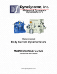
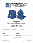
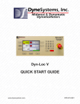
1
FROM DYNE SYSTEMS, INC. The Data Assistant – Electric Motor Service Industry software supplied by Dyne Systems, Inc. (DSI) is intended to provide users a method of gathering and reporting speed, torque and power measurements during load tests. FEATURES SUMMARY: Compatible with Windows® XP (or greater) based computers Simple stand-alone application Interfaces seamlessly with Dyne Systems current dynamometer controllers Ethernet or serial port communications supported AC or DC motor data entry selections Reports include customer information, job number, and motor serial number Editable drop down list boxes simplifies data entry Snap-shot or timed logging of dynamometer data Report format in editable .docx file format Report can include company logos NOTE: This manual is intended for use by qualified personnel only. Thank you for purchasing this product from Dyne Systems. Our staff is at your disposal, should you need information or support that is not found in this manual. VERSION INFORMATION Identifier: Revision: N/A Effective Date: v1.0 3/12/15 Document Catalog Number: v1.0 Author: Nick Quatsoe Controls, Dynamometers, System Integration and Test Cell Automation Dyne Systems, Inc. W209 N17391 Industrial Drive Jackson, Wisconsin 53037 phone: 800.657.0726 website: www.dynesystems.com Data Assistant – Electric Motor Service Industry © Copyright Dyne Systems, Inc v1.0 i DOCUMENT HISTORY REVISION HISTORY Revision Number Revision Date Summary of Changes Author 1.0 03/12/2015 Initial Release Nick Quatsoe DISTRIBUTION This document has been distributed to: Name ii Data Assistant – Electric Motor Service Industry © Copyright Dyne Systems, Inc Title v1.0 TABLE OF CONTENTS 1 Introduction................................................................................................... 1 2 Installation..................................................................................................... 3 2.1 Operating System Requirements ................................................................................... 3 2.2 Hardware Requirements ................................................................................................ 3 2.3 Installation of Data Assistant – EMSI ............................................................................. 3 3 Device Setup ................................................................................................. 5 4 Walkthrough.................................................................................................. 7 4.1 Test Step Process .......................................................................................................... 7 Step 1: Motor Type ................................................................................................... 8 Step 2: Testing Information ...................................................................................... 8 Step 3: Data Logging ............................................................................................... 9 Start Logging .................................................................................................... 9 Snapshot Button............................................................................................... 9 Stop Logging .................................................................................................... 9 Step 4: Saving the Report .......................................................................................10 5 6 Data Backup, Report Management, Adding a Logo ................................ 11 5.1 Backing Up Data...........................................................................................................11 5.2 Managing Reports ........................................................................................................11 5.3 Adding a Company Logo ..............................................................................................11 Appendix ..................................................................................................... 13 6.1 Test Durations ..............................................................................................................13 6.2 Sample Reports ............................................................................................................13 AC Motor Test - Sample Report .............................................................................14 DC Motor Test – Sample Report .............................................................................15 Test Using Nameplate Image – Sample Report .....................................................16 Data Assistant – Electric Motor Service Industry © Copyright Dyne Systems, Inc v1.0 iii iv Data Assistant – Electric Motor Service Industry © Copyright Dyne Systems, Inc v1.0 1 INTRODUCTION Data Assistant – Electric Motor Service Industry (EMSI) is a stand-alone software application that was developed specifically for the electric motor service industry. It functions as a data gathering and reporting application that makes it easy for the user to provide load test data to their customers. Data Assistant - EMSI interfaces seamlessly with Dyne Systems’ Dyn-Loc V and Inter-Loc V dynamometer controllers to specifically gather speed, torque, and power measurements during load tests. This data is used to create a report in the form of a Microsoft Word document (.docx). Data Assistant – Electric Motor Service Industry © Copyright Dyne Systems, Inc v1.0 1 2 Data Assistant – Electric Motor Service Industry © Copyright Dyne Systems, Inc v1.0 2 INSTALLATION 2.1 OPERATING SYSTEM REQUIREMENTS Data Assistant – EMSI is compatible with Windows® XP (or greater) based computers. 2.2 HARDWARE REQUIREMENTS Data Assistant – EMSI will run on any personal computer running any of the previous listed operating systems. Also, a Dyne Systems, Inc. dynamometer controller, either a Dyn-Loc V or Inter-Loc V, is required to log data. 2.3 INSTALLATION OF DATA ASSISTANT – EMSI Simply run Install-DataAssistant_EMSI-x.x.x.x.exe and follow the prompts. Installation takes less than a minute. Launching the program for the first time will cause additional folders to be created. You will receive prompts indicating that new files are being modified. This is normal. Data Assistant – Electric Motor Service Industry © Copyright Dyne Systems, Inc v1.0 3 4 Data Assistant – Electric Motor Service Industry © Copyright Dyne Systems, Inc v1.0 3 DEVICE SETUP There are two ways to connect Data Assistant – EMSI: Serial and Ethernet. To configure the connection click Configure > Controller… Select RS-232 (COM) for a Serial connection. You will need to select both the Port and the Baud Rate. Ethernet is selected by default for first use. The default IP Address (192.168.2.10) is also provided for first time use. NOTE: Any changes made here need to be made in the Dyn-Loc V/Inter-Loc V as well (e.g., using a different IP Address or Baud Rate). Click the Save button to immediately apply the changes. Click Cancel to disregard any changes that were made. As shown below, Data Assistant – EMSI will indicate in the lower left corner if the device is connected to the Dyn-Loc V/Inter-Loc V. Data Assistant – Electric Motor Service Industry © Copyright Dyne Systems, Inc v1.0 5 6 Data Assistant – Electric Motor Service Industry © Copyright Dyne Systems, Inc v1.0 4 WALKTHROUGH 4.1 TEST STEP PROCESS Using Data Assistant - EMSI is broken down into four individual steps. These steps are clearly labeled at the bottom of the application at all times. The left and right arrows are used to move forward and backward (when applicable) between test steps. Hover the mouse over any of the steps to see a short description. Also, the steps will be filled in with color as you move throughout the test to show where you are in the process. See below: Step One Step T Two Step Three Th Step F Four Data Assistant – Electric Motor Service Industry © Copyright Dyne Systems, Inc v1.0 7 STEP 1: MOTOR TYPE Select the motor type: AC or DC. The current selection will be indicated by a pulsing green box. Each motor type will provide a slightly different informational form to fill out. When ready, click the Next arrow to move to Step 2. STEP 2: TESTING INFORMATION Fill out as much information as desired. Information is broken into general and motor-specific sections. Labels that are hyperlinks (e.g. Manufacturer) can be clicked to add custom entries. These entries will persist until removed through the same interface. Optionally, a picture of the nameplate, or motor itself, can be inserted into the report immediately following the entered information. Click the Photo… icon to select the picture, if any. Allowable picture types are .bmp, .gif, .jpg, .jpeg, and .png. The picture will automatically be scaled to fit on the first page of the report while maintaining aspect ratio. When ready, click the Next arrow to move to Step 3. You can also click the Back arrow to change the selected motor type. Entered information will persist while moving back and forth between steps. 8 Data Assistant – Electric Motor Service Industry © Copyright Dyne Systems, Inc v1.0 STEP 3: DATA LOGGING START LOGGING Data logging can only be initiated if the device is connected. If connected, set the desired logging interval and/or press the Start button. See below: NOTE: Logging can be started without selecting a logging interval. In this case, data will not be recorded until an interval is selected or the Snapshot button is clicked. The interval can be changed, a snapshot taken, or the logging paused, at any point during logging. SNAPSHOT BUTTON The snapshot functionality logs data the moment the button is pressed. This can be done while logging data at a given interval. The final report will denote a snapshot by displaying a small camera icon in the Status column for the given data row. STOP LOGGING To stop data logging, simply click the Stop button. A prompt will appear to confirm this action. If not stopped, the logging will automatically stop after 1000 logging samples are taken. The number of collected samples are displayed above the Snapshot button and will update each time a sample is taken. Data Assistant – Electric Motor Service Industry © Copyright Dyne Systems, Inc v1.0 9 STEP 4: SAVING THE REPORT Save the report with the desired name. Previously saved reports will be shown below. They can be single-clicked in order to auto-populate their name into the new file name field. This makes for quick overwriting or appending a number to the end (e.g., MyVeryLongTestTitle Æ MyVeryLongTestTitle2). “Open report after save” checkbox provides the option of having the report automatically launched via Microsoft Word after it is generated and saved. Once set, this preference will be remembered for each additional report save. Previously created files can be sorted based on File Name, Date Created, or Last Modified date. After saving (or cancelling the save), the tool can be restarted for another test or simply closed. 10 Data Assistant – Electric Motor Service Industry © Copyright Dyne Systems, Inc v1.0 5 DATA BACKUP, REPORT MANAGEMENT, ADDING A LOGO 5.1 BACKING UP DATA Create a copy of the following folder in order to backup form configurable data and generated reports: Root Drive\Data Assistant – Electric Motor Service Industry\ NOTE: Root Drive is usually C:\. Nothing outside of the above folder structure will be copied (e.g., company logo, although the path will be retained). 5.2 MANAGING REPORTS Previously created reports can be managed by clicking File > Manage Reports. The previously created reports will be displayed in alphabetical order. They can also be sorted by Date Created, Last Modified date, or the File Size. From this screen, previously created reports can be opened, renamed, and even deleted. 5.3 ADDING A COMPANY LOGO You can select a company logo to be used in the finished report. This image will be used for further reports unless modified. To configure the logo click Configure > Report… Data Assistant – Electric Motor Service Industry © Copyright Dyne Systems, Inc v1.0 11 12 Data Assistant – Electric Motor Service Industry © Copyright Dyne Systems, Inc v1.0 6 APPENDIX 6.1 TEST DURATIONS See the table below for the approximate length of data logging per given sample rate: Sample Rate (seconds) Test Duration --- Until 1000 snapshots have been taken 1 0 hr. 16 min. 36 sec. 2 0 hr. 33 min. 18 sec. 5 1 hr. 23 min. 18 sec. 10 2 hr. 46 min. 36 sec. 20 5 hr. 33 min. 18 sec. 6.2 SAMPLE REPORTS The following pages contain samples of typical reports. Both AC and DC examples are shown. Each report utilizes a company logo (in this case, Dyne Systems, Inc.). The last example shows a report which includes a picture of the nameplate. The subsequent page of that report contains the recorded data. Any information that was supplied during Step 2 can be directly modified in the report. All other data is locked to ensure test legitimacy. Data Assistant – Electric Motor Service Industry © Copyright Dyne Systems, Inc v1.0 13 AC MOTOR TEST - SAMPLE REPORT 14 Data Assistant – Electric Motor Service Industry © Copyright Dyne Systems, Inc v1.0 DC MOTOR TEST – SAMPLE REPORT Data Assistant – Electric Motor Service Industry © Copyright Dyne Systems, Inc v1.0 15 TEST USING NAMEPLATE IMAGE – SAMPLE REPORT 16 Data Assistant – Electric Motor Service Industry © Copyright Dyne Systems, Inc v1.0