1
RC32xxx Ethernet Driver Design
Specification in Linux
Application Note
AN-473
By Harpinder Singh and Haofeng Kou
Notes
Overview
This application note provides guidelines to software developers for writing the Ethernet device driver for
the integrated Ethernet hardware interface on IDT's RC32xxx integrated communications processors
family. There are up to two Ethernet interface ports available on IDT's RC32xxx integrated communications
processors. The integrated processors have dedicated DMA channels for data transmit and receive over
the Ethernet ports. The core functionality of the Ethernet driver is revealed in the initialization, data-transmit,
and data-receive operations. This application note presents in detail these three key operations of the
Ethernet driver while briefly describing the overall design specification of the driver. Prior to using this application note, it is recommended for the reader to go through the architecture of the Ethernet interface and
the on-chip DMA Engine as illustrated in the appropriate processor user manual (see References at the end
of this application note). Further, in order to discuss the intricacies of Ethernet driver implementation, the
application note uses the Ethernet driver for RC32438 integrated processor ("/linux/driver/net/acacia.c") as
an example.
Ethernet Interface Overview
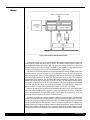
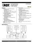
The salient features of the Ethernet interface on IDT RC32xxx are listed below and the architecture is
shown in Figure 1:
– I0 and 100 Mb/s ISO/IEC 8802-3:1996 compliant
– Up to two IEEE 802.3u compatible Media Independent Interfaces (MII) with serial management
interface
– MII supports IEEE 802.3u auto-negotiation speed selection
– 64 entry hash table based multicast address filtering
– 512 byte transmit and receive FIFO
– Flow control Descriptions outlined in IEEE Std. 802.3x-1997
1 of 27
© 2004 Integrated Device Technology, Inc.
June 16, 2004
DSC 6425
IDT Application Note AN-473
Notes
Figure 1 Ethernet Interface with Management Feature
The RC32xxx contains up to two 10/100 Mb/s ISO/IEC 8802-3:1996 compliant Ethernet interfaces. An
external Ethernet physical layer device (PHY) connects to each Ethernet interface through an IEEE STD
802.3u-1995 Media Independent Interface (MII). This allows each Ethernet interface to be used with a
multitude of physical layers, such as 10BASE-T, 100BASE-TX, and 100BASE-FX. Each Ethernet interface
is capable of performing flow control functions as outlined in IEEE STD 802.3x-1997.
A key feature of the Ethernet interface is the 512 byte input/output FIFO between the DMA interface and
the Ethernet module. The input and output FIFO are not intended to hold a large number of packets, but
merely to compensate for latency in accessing data by the DMA controller. Packet data to be transmitted is
written by the DMA controller into the output FIFO. The moment the data in the output FIFO exceeds the
programmable transmit threshold value, the Ethernet MAC begins transmission (preamble, start of frame
delimiter, and then data from the output FIFO) if the line is not busy. The DMA controller transfers data to
the output FIFO only when space for 16 FIFO words is available. Fewer words are allowed to be transferred
if the count field, describing length of the packet to be transmitted, in the DMA descriptor reaches zero.
When this happens, a finished event is generated that is passed on to the CPU as an interrupt.
Whenever 16 words of Ethernet packet data are available in the input FIFO or an end-of-packet condition is encountered, the DMA engine is triggered to transfer the packet data to the memory. A DMA done
event is generated whenever an end-of-packet condition is encountered. This is passed on to the CPU as
an interrupt marking completion of the receipt of the Ethernet packet.
The address recognition logic checks the destination address of the received packet. If the destination
address in the packet matches the port MAC address, the packet is passed to the DMA engine. In the case
of a mismatch, the packet is dropped by the Ethernet module. The address recognition logic supports multicast and broadcast addresses. Hash algorithm is used by the address recognition logic to determine if the
multicast packet is to be accepted or dropped. Further, the address recognition logic supports four Ethernet
Station address registers. This allows the user to program four different Ethernet MAC addresses per port
to receive all the data packets addressed to any of these MAC addresses. In other words, address recogni-
2 of 27
June 16, 2004
IDT Application Note AN-473
Notes
tion logic provides a mechanism to the Ethernet driver to exhibit to the external world four ports instead of
one port. For normal operation, all the four Ethernet Station address registers are programmed with one
MAC address.
The Ethernet MII management interface provides a serial interface for controlling and monitoring the
PHY devices. Both of the Ethernet ports share the same MII management interface. In order to read a
register, the PHY address and register address is written to the MII management address register. Once the
data not valid bit in the MII indicator register is cleared, the value of the register is obtained by reading MII
management read data register. It is possible to perform a single read or multiple reads by programming the
MII management command register. When writing to a PHY register, first the PHY address and register
address is written to the MII management address register. Subsequently, the data value is written to the
MII management write data register. When the busy bit is cleared in the MII management indicator register,
it marks the completion of the write operation.
System Architecture
DMA
The transmit/receive DMA operation constitutes the core of the Ethernet Driver. It handles all the data
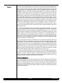
transfer to/from the FIFO from/to the memory. For efficient operation, dedicated DMA channels are associated with transmit and receive paths of each Ethernet interface port. The table below summarizes the DMA
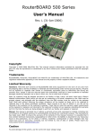
channel assignments for the IDT RC32xxx integrated processor family. Figure 2 shows the DMA Descriptor
Register.
IDT™ Interprise™
Integrated
Communications
Processor
Evaluation
Boards
Ethernet
Port
Transmit
DMA
Receive
DMA
RC32434
EB434
Eth0
Channel 1
Channel 0
RC32365
RC32336
EB365
EB336
Eth0
Channel 1
Channel 0
Eth1
Channel 3
Channel 2
RC32438
EB438
PMC438
Eth0
Channel 3
Channel 2
Eth1
Channel 5
Channel 4
EB351
RP351
EB355
RP355
Eth0
Channel 10
Channel 9
RC32351
RC32355
Table 1 DMA Channel Assignments for the RC32xxx Family
Figure 2 DMA Descriptor Register
3 of 27
June 16, 2004
IDT Application Note AN-473
Notes
The first word of the DMA descriptor is the "Control Field," which carries count and interrupt flag information. The count field specifies the length of the packet when transmitting Ethernet packets. While receiving
Ethernet packets, the count field is set to a maximum value (1536) that allows reception of data packets of
all possible lengths. The interrupt flags are used to control the generation of interrupts on "DONE" and
"FINISHED" conditions. The "DONE" condition implies completion of the receipt of the packet. The
"FINISHED" condition happens when the count field becomes zero, typically when the packet is transmitted
completely. A chain interrupt can also be generated for these conditions. This can be used to signal the
Ethernet driver to prepare more resources for the DMA operations. Such an approach can be used to allocate minimal DMA descriptors/buffers to the DMA channels while at the same time keeping up with the
required data rates. With memory resources being available in abundance in today's systems, the chain
interrupts are more likely to be used as part of the algorithms to handle bursts of data traffic that consumes
DMA resources at a much faster rate than what can be handled by the CPU. The most significant bits of the
control field of the DMA descriptor indicate the status of the "FINISHED", "DONE", or "Terminated" event.
The second word of the DMA descriptor is the current address pointer. This memory pointer is used to
point to the memory buffer during receive or transmit of the packet. A physical address is loaded into the
current address pointer.
The third word of the DMA descriptor carries the device control and status information. The control bits
in the receive DMA descriptors are used to set the first/last DMA descriptor information. In general, the
DMA operation allows a packet to be received by using multiple DMA descriptors. For such a case, the first
descriptor needs to be marked first in the "DEVCS" and, likewise, the last descriptor marked as last. For the
sake of simplicity, all the Ethernet packets received or transmitted use a single DMA descriptor. The
DEVCS control field is used to mark the descriptor both first and last. The transmit DMA descriptor has a
few more control bits for overriding packet padding, CRC generation, and permitting transmission of the
huge packets. The status information is written back by the DMA channel after the completion of the DMA
operation associated with the DMA descriptor.
The status information carried by the DEVCS field is very important and is extensively used by the
Ethernet driver. For the receive operation, the driver looks for the "Receive OK: ROK" status flag, which is
set if the overrun, CRC error, code violation, and length errors do not occur. If the DMA descriptor on packet
receive does not show "ROK" as set, the corresponding status error bits are checked by the Ethernet driver
to update the statistics. For receive, the most significant half word of DEVCS field shows the length of the
packet received. Likewise, the DEVCS field in the transmit DMA descriptor has a "Transmit OK: TOK"
status bit that marks successful transmission. This bit gets set when transmit underflow error, oversized
frame, excessive deferrals, excessive collisions, and late collision errors do not occur.
The last word of the DMA descriptor is the link field, which is used to link the DMA descriptors together.
For the receive operation, all the DMA descriptors are linked except the last one. The last DMA descriptor in
the list has the "Chain on DONE" bit set. Such a mechanism allows continuous receipt of the Ethernet
packets. For the transmit operation, the DMA descriptors are generally not linked together. However, they
may get linked together temporarily while waiting in the transmit queue.
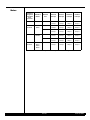
Interrupt Controller
The interrupt controller on the processor multiplexes various interrupts initiated by the Ethernet interface
and the associated DMA channels. These events are placed on one or more hardware interrupt inputs of
the CPU. The RC32xxx processor family uses "Group N" nomenclature to implement multiplexing of the
interrupts from integrated peripherals, where "N" indicates the CPU IRQ input. The details of the interrupt
controller groups used by the Ethernet interfaces for different members of the RC32xxx processor family
are shown in the table below.
4 of 27
June 16, 2004
IDT Application Note AN-473
Notes
IDT™
Interprise™
Integrated
Communica
tions
Processor
Evaluation
Boards
Ethernet
Port
Transmit
Interrupt
Receive
Interrupt
Underflow
Interrupt
Overflow
Interrupt
RC32434
EB434
Eth0
Bit 1 of
Group 3
Bit 0 of
Group 3
Bit 10 of
Group 5
Bit 9 of
Group 5
RC32365
RC32336
EB365
EB336
Eth0
Bit 1 of
Group 3
Bit 0 of
Group 3
Bit 5 of
Group 5
Bit 4 of
Group 5
Eth1
Bit 3 of
Group 3
Bit 2 of
Group 3
Bit 8 of
Group 5
Bit 7 of
Group 5
Eth0
Bit 3 of
Group 3
Bit 2 of
Group 3
Bit 13 of
Group 5
Bit 12 of
Group 5
Eth1
Bit 5 of
Group 3
Bit 4 of
Group 3
Bit 16 of
Group 5
Bit 15 of
Group 5
Eth0
Bit 10 of
Group 3
Bit 9 of
Group 3
Bit 23 of
Group 5
Bit 22 of
Group 5
RC32438
RC32351
RC32355
EB438
PMC438
EB351
RP351
EB355
RP355
Table 2 Interrupt Controller Groups for the RC32xxx Family
5 of 27
June 16, 2004
IDT Application Note AN-473
Notes
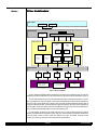
Driver Architecture
User Level
/Proc /Dev
/Proc /Dev
Linux Kernel
Scheduler
PROC Interface
DEV Interface
Soft IRQ
Ethernet Driver
Transmit
ISR
Driver
Module
Transmit
Tasklet
Overflow
ISR
Transmit
Top-Half
Underflow
ISR
Linux Kernel
Receive
ISR
DMA
Access
Receive
Tasklet
Receive
Top-Half
MIIPHY
ISR
Do IRQ
Receive
Overflow
Transmit
Underflow
Transmit
DMA
Receive
DMA
MII
PHY
Hardware
Interrupt Controller
Ethernet Transmit
DMA Channel
Ethernet & DMA
(Finish Done Halt and
Error events)
GPIO
Interface
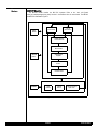
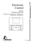
Figure 3 Driver Architecture
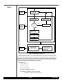
Figure 3 illustrates the Ethernet driver architecture. In this section of the application note, the user level
interface for the driver is described. The rest of the functions in the device driver are described in Section 5.
The user level interface for the driver is provided mainly for debug or informational purposes. This interface is provided by the "/proc" file system. In other words, the Ethernet device driver exports information to
the user via /proc, which allows use of common Linux commands to obtain information about the state of
the driver or Ethernet interface. The kernel allocates a page of memory for the driver to return information to
the user space. In order to do this, the driver has to implement a "read_proc" function that will write information to the Kernel allocated page whenever the /proc file system is read.
For /proc support, the driver has to include <linux/proc_fs.h> in order to define functions that may be
invoked. The Ethernet driver implements "acacia_read_proc", which provides the information whenever the
/proc file system is read. In order to attach this function to the /proc file system, the driver invokes
"create_proc_read_entry" function in device probe function as listed below:
6 of 27
June 16, 2004
IDT Application Note AN-473
Notes
lp->ps = create_proc_read_entry ("net/rc32438", 0, NULL, acacia_read_proc, dev);
Where "lp->ps" point to the "proc_dir_entry" structure declared in the Ethernet interface local data structure. The first argument to the function is the name of the /proc entry. The second argument is for file
permission for directory "/proc/net/rc32438". A value of zero for this argument implies a world-readable
mask. The third argument points to the parent directory, which is set to NULL. The fourth argument is the
"read_proc" function to be invoked when the file "/proc/net/rc32438" is read. The fifth argument is the data
pointer that will be passed to the "read_proc" function, which is a pointer to the Ethernet device. Whenever
"acacia_read_proc" is invoked, it provides count of DMA halt, run, race and collision. The driver also implements "remove_proc_entry" function to remove the /proc entry created by the driver before its module is
unloaded.
Driver Mode Implementation
This section describes the transmit, receive, and initialization functions in detail and briefly explains the
other Ethernet driver functions.
Packet Transmission
The packet that is destined to be sent out over the Ethernet is passed by the kernel to the Ethernet
driver. The Ethernet driver provides a "hard_start_transmit" function that is invoked by the kernel for transmitting the packet. The kernel provides two arguments to this function: socket buffer and pointer to device.
The socket buffer "sk_buff" carries the packet. The packet includes the Ethernet header and is required to
be sent on the physical media without any further modifications. The "hard_start_transmit" is called again
by the Kernel only after the previous call returns. This is done by using a spinlock mechanism in the
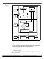
"net_device" structure. Figure 4 illustrates the packet transmission flow.
Once the Ethernet driver send function is called, it first locks the device data structure to gain exclusive
access to it. The code commentary is illustrated below:
static int acacia_send_packet(struct sk_buff *skb, struct net_device *dev)
{
Obtain the pointer to the "acacia_local" device structure. The local device structure has device register
base addresses for DMA, Ethernet, transmit DMA descriptor ring, receive DMA descriptor ring, etc.
struct acacia_local*lp = (struct acacia_local *)dev->priv;
Lock the local device data structure to gain exclusive access to it.
spin_lock_irqsave(&lp->lock, flags);
Obtain the pointer to the next available transmit descriptor in the ring. It is checked to determine that the
transmit DMA descriptor is not in use. The transmit finish interrupt is masked in order to avoid any race
conditions between the send function and the interrupt handler.
td = &lp->td_ring[lp->tx_chain_tail];
local_writel(local_readl(&lp->tx_dma_regs->dmasm) |
DMASM_f_m , &lp->tx_dma_regs->dmasm);
7 of 27
June 16, 2004
IDT Application Note AN-473
Notes
Kernel sends packet
to the driver
Linux
Kernel
Enable the Interrupt
Disable the Interrupt
Check the
waiting queue
Linux
Ethernet
Driver
Full
netif_stop_queue
Not Full
Prepare the transmit
DMA descriptors
Start the transmit DMA
Enable interrupts
Ethernet & DMA
(Finish & Error events)
Hardware
Interrupt Controller
Ethernet Transmit
DMA Channel
Figure 4 Packet Transmission Flow Chart
If the transmit DMA descriptor is in use, it indicates that the transmit ring is full. This is abnormal and can
occur only under heavy stress conditions. To respond to this event, the driver stops the transmit queue from
receiving any more packets from the kernel: the packet to be transmitted is dropped by freeing the SKB; the
local device data structure is unlocked; transmit finish event is unmasked; and device statistics is updated.
The function then returns without transmitting the current packet.
if(td->control != 0){
netif_stop_queue(dev);
lp->stats.tx_dropped++;
dev_kfree_skb_any(skb);
spin_unlock_irqrestore(&lp->lock, flags);
local_writel(local_readl(&lp->tx_dma_regs->dmasm) &
~DMASM_f_m , &lp->tx_dma_regs->dmasm);
8 of 27
June 16, 2004
IDT Application Note AN-473
Notes
return 1;
}
The most important part of the transmit routine prepares the transmit descriptor and initiates the transmission. The physical address of the buffer data pointer is loaded to the Current Address field of the DMA
descriptor. To reiterate, physical address is used because the address is being used in hardware. Translation from virtual to physical address happens only as part of the program execution and is not done when
the DMA engine performs memory access. This is the reason why the DMA engine needs physical
addresses in the Current Address and the Link field of the DMA descriptor. The Control field of the DMA
descriptor is initialized with the length of the packet and the IOF (interrupt on Finish) event is set. The length
field in the Control field tells the DMA engine how many bytes need to be transmitted.
length = skb->len;
td->ca = virt_to_phys(skb->data);
td->control = DMA_COUNT(length) |DMAD_iof_m;
The Link field of the DMA descriptor is untouched so far and may get used only if there are already
pending packets for transmission. Once the DMA descriptor is initialized, it is important to determine the
state of the DMA channel. If the transmit DMA channel is idle, the status of the transmit queue is checked.
If the transmit wait queue is empty, the DMA descriptor is loaded into the DPTR register that begins the
transmit operation. If the transmit wait queue is not empty, the DMA descriptor is linked to the end of the
wait queue and the DMA descriptor at the head of the queue is loaded into the DPTR register to start the
transmit operation. The head of the transmit chain is loaded in both of the above cases. If only one packet is
to be transmitted, the tail and the head of the list are the same. If two or more packets are waiting in a
queue to be transmitted, the head points to the first packet in the wait queue. A dummy read operation is
performed to flush the write buffers of the CPU in order to flush out all the pending writes.
if(!(lp->tx_dma_regs->dmac & DMAC_run_m))
{
if( lp->tx_chain_status == empty )
{
lp->tx_dma_regs->dmadptr =
virt_to_phys(&lp->td_ring[lp->tx_chain_head]);
lp->tx_chain_tail = (lp->tx_chain_tail + 1) &
ACACIA_TDS_MASK;
lp->tx_chain_head = lp->tx_chain_tail;
}
else
{
lp->td_ring[(lp->tx_chain_tail-1)&
ACACIA_TDS_MASK].link = virt_to_phys(td);
dummyReadVar = lp->tx_dma_regs->dmadptr;
lp->tx_dma_regs->dmadptr =
virt_to_phys(&lp->td_ring[lp->tx_chain_head]);
lp->tx_chain_tail = (lp->tx_chain_tail + 1) &
ACACIA_TDS_MASK;
9 of 27
June 16, 2004
IDT Application Note AN-473
Notes
lp->tx_chain_status = empty;
lp->tx_chain_head = lp->tx_chain_tail;
}
}
If the DMA channel is not idle, the packet needs to be put in the wait queue. A check is made to determine whether or not the wait queue is empty. If the wait queue is empty, a new wait queue is created with
the head of the queue pointing to the current packet. Otherwise, the packet is en-queued at the end of the
already existing wait queue.
if( lp->tx_chain_status == empty )
{
lp->tx_chain_tail = (lp->tx_chain_tail + 1) &
ACACIA_TDS_MASK;
lp->tx_chain_status = filled;
}
else
{
lp->td_ring[(lp->tx_chain_tail-1)& ACACIA_TDS_MASK].link
= virt_to_phys(td);
lp->tx_chain_tail = (lp->tx_chain_tail + 1) &
ACACIA_TDS_MASK;
}
Before returning, the transmit routine enables the "Finish" interrupt, unlocks local device access, and
updates the transmission start time in jiffies. The network layer may use this time period to determine if the
upper layer needs to take a transmit timeout to clear the problem associated with any stuck packets in the
queue or hardware.
local_writel(local_readl(&lp->tx_dma_regs->dmasm) &
~DMASM_f_m , &lp->tx_dma_regs->dmasm);
dev->trans_start = jiffies;
spin_unlock_irqrestore(&lp->lock, flags);
The buffer passed by the higher layer is freed once the transmission of the packet completes. The
completion of the packet transmission is reported by raising the "Finish" interrupt.
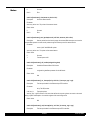
Transmit Interrupt
After the driver starts the transmit operation, the DMA generates an interrupt on completion of the transmission of the packet by raising the "DMA Finish" interrupt. The Ethernet driver handles the transmit finish
DMA interrupt using the transmit interrupt handler ISR. The transmit handler processing is divided into two
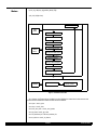
parts, Top Half and a tasklet. The Top Half interrupt handling does a minimal set of mandatory operations to
keep the interrupt routine small. Figure 5 illustrates the transmission interrupt flow.
10 of 27
June 16, 2004
IDT Application Note AN-473
Notes
Scheduler
Do_irq
Linux
Kernel
Soft IRQ
Mask the transmit F E Interrupt
Lock the share data
Schedule the transmit
Tasklet
Linux
Ethernet
Driver
Top Half
Maintain the waiting queue
Disable the Interrupt
DMA descriptors
Transmit
Tasklet
Polling the transmit
DMA descriptors
Enable the Interrupt
Unlock the share data
Unmask the transmit F E Interrupt
Hardware
Ethernet and DMA
(Finish and Error Events)
Interrupt Controller
Ethernet Transmit
DMA Channel
Figure 5 Transmit Interrupt Flow Chart
The interrupt handler locks access to the local device data structure and masks the finish interrupts on
the transmit DMA channel. Further, it checks the DMA status for error conditions, schedules the transmit
tasklet, and clears the sticky bits.
spin_lock(&lp->lock);
local_writel(local_readl(&lp->tx_dma_regs->dmasm) |
(DMASM_f_m | DMASM_e_m), &lp->tx_dma_regs->dmasm);
dmas = local_readl(&lp->tx_dma_regs->dmas);
if (dmas & (DMAS_f_m | DMAS_e_m))
11 of 27
June 16, 2004
IDT Application Note AN-473
Notes
{
tasklet_hi_schedule(lp->tx_tasklet);
if (dmas & DMAS_e_m)
ERR(__FUNCTION__ ": DMA error\n");
}
local_writel(~dmas, &lp->tx_dma_regs->dmas);
Before returning, the interrupt handler checks the transmit wait queue. If the transmit wait queue is not
empty, it loads the list of waiting packets to the NDPTR register. Finally, it unlocks access to the local device
data structure and returns.
if(lp->tx_chain_status == filled &&
(local_readl(&(lp->tx_dma_regs->dmandptr)) == 0))
{
local_writel(virt_to_phys(&lp->td_ring[lp->tx_chain_head]),
&(lp->tx_dma_regs->dmandptr));
lp->tx_chain_status = empty;
lp->tx_chain_head = lp->tx_chain_tail;
}
spin_unlock(&lp->lock);
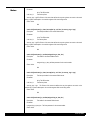
Receive Interrupt
After the Ethernet interface receives a packet, it generates an interrupt. The interrupt is flagged by the
DMA channel associated with the Ethernet receive engine. On completion of the receipt of a valid packet,
the DMA channel raises the "DMA DONE" interrupt. The Ethernet driver handles this using the receive
interrupt handler ISR, which is divided into Top Half and a tasklet. The packets are passed to the higher
layers after performing sanity checks in the tasklet. The invalid packets are discarded by the interrupt
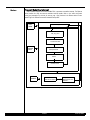
handler. Also, the tasklet re-initializes the DMA descriptors used during the receipt of the packet. Figure 6
illustrates the receive interrupt flow.
12 of 27
June 16, 2004
IDT Application Note AN-473
Notes
Do_irq
Scheduler
Linux
Kernel
Linux
Ethernet
Driver
Top Half
Soft IRQ
Mask the receive D H E Interrupt
Lock the share data
Schedule the receive
Tasklet
Disable the Interrupt
DMA descriptors
Receive
Tasklet
Polling the receive
DMA descriptors
Enable the Interrupt
Unlock the share data
Unmask the receive D H E Interrupt
Hardware
Ethernet and DMA
(Done, Halt, and Error
Events)
Interrupt Controller
Ethernet Receive
DMA Channel
Figure 6 Receive Interrupt Flow Chart
The first step in the receive interrupt handler is to lock access to the local device data structure. The
DMA DONE/HALT/ERROR interrupts are also masked. Next, the status of the DMA channel is read. If a
valid DONE, HALT, or ERROR interrupt is present, then the receive handler tasklet is scheduled. Prior to
returning, the interrupt handler unlocks access to the local device data structures.
lp = (struct acacia_local *)dev->priv;
spin_lock(&lp->lock);
/* Mask D H E bit in Rx DMA */
local_writel(local_readl(&lp->rx_dma_regs->dmasm) | (DMASM_d_m | DMASM_h_m | DMASM_e_m),
&lp->rx_dma_regs->dmasm);
13 of 27
June 16, 2004
IDT Application Note AN-473
Notes
dmas = local_readl(&lp->rx_dma_regs->dmas);
local_writel(~dmas, &lp->rx_dma_regs->dmas);
if(dmas & (DMAS_d_m | DMAS_h_m | DMAS_e_m))
{
tasklet_hi_schedule(lp->rx_tasklet);
}
spin_unlock(&lp->lock);
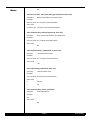
Init and Re_Init
These functions are used by the Ethernet driver to initialize/re-initialize the Ethernet interface. Some of
the major steps in the initialization of the Ethernet driver are described below. Figure 7 illustrates the initialization flow.
Hardware specific initialization begins with allocating memory for the local device data structure.
lp = (struct acacia_local *)kmalloc(sizeof(*lp), GFP_KERNEL);
memset(lp, 0, sizeof(struct acacia_local));
The network device private data structure is pointed to the local device data structure. Next, the device
Ethernet interface data structure is used to allocate the DMA and Ethernet base address registers. The
following code shows the initialization for the Ethernet interface port 0.
dev->priv = lp;
lp->rx_irq = bif->rx_dma_irq;
lp->tx_irq = bif->tx_dma_irq;
lp->ovr_irq = bif->rx_ovr_irq;
lp->und_irq = bif->tx_und_irq;
lp->eth_regs = ioremap_nocache(bif->iobase, sizeof(*lp->eth_regs));
lp->rx_dma_regs = ioremap_nocache(DMA0_PhysicalAddress + 2 *
DMA_CHAN_OFFSET,sizeof(struct DMA_Chan_s));
lp->tx_dma_regs =ioremap_nocache(DMA0_PhysicalAddress + 3 *
DMA_CHAN_OFFSET, sizeof(struct DMA_Chan_s));
Subsequently, the DMA descriptors for receive and transmit paths are allocated by the Ethernet initialization routine. On successful allocation and initialization of transmit and receive DMA descriptor memory,
the local device data structure is unlocked.
lp->td_ring =(DMAD_t)kmalloc(TD_RING_SIZE +
RD_RING_SIZE, GFP_KERNEL);
dma_cache_inv((unsigned long)(lp->td_ring),
TD_RING_SIZE + RD_RING_SIZE);
lp->td_ring = (DMAD_t )KSEG1ADDR(lp->td_ring);
14 of 27
June 16, 2004
IDT Application Note AN-473
Notes
lp->rd_ring = &lp->td_ring[ACACIA_NUM_TDS];
spin_lock_init(&lp->lock);
Scheduler
Linux
Kernel
Disable DMA
Reset the Ethernet Port
Disable Tasklet
Linux
Ethernet
Driver
Init the Transmit and
Receive DMA Descriptor
Start the Receive DMA Channel
Unmask the Interrupts for
Transmit and Receive
Setting the Ethernet Registers
Enable the Tasklet
netif_start_queue
Hardware
Ethernet and DMA
Interrupt Controller
Figure 7 Initialization Flow Chart
As a final step, the Ethernet driver initialization routine initializes the network device data structure with
the device driver methods and creates transmit and receive tasklets.
dev->open = acacia_open;
dev->stop = acacia_close;
dev->hard_start_xmit = acacia_send_packet;
dev->get_stats= acacia_get_stats;
dev->set_multicast_list = &acacia_multicast_list;
dev->tx_timeout = acacia_tx_timeout;
15 of 27
June 16, 2004
IDT Application Note AN-473
Notes
dev->watchdog_timeo = ACACIA_TX_TIMEOUT;
lp->rx_tasklet = kmalloc(sizeof(struct tasklet_struct),
GFP_KERNEL);
tasklet_init(lp->rx_tasklet, acacia_rx_tasklet, (unsigned long)dev);
lp->tx_tasklet = kmalloc(sizeof(struct tasklet_struct),
GFP_KERNEL);
tasklet_init(lp->tx_tasklet, acacia_tx_tasklet, (unsigned long)dev);
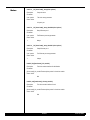
Restart
The Ethernet driver restarts the Ethernet interface under certain situations. Refer to the "static int [board
name]_restart (struct net_device *dev)" Ethernet driver functions for more details. Figure 8 illustrates the
restart flow.
Disable the Interrupts for
Transmit Receive Overflow
and Underflow
Mask the Interrupts for
Transmit Receive Overflow
and Underflow
Re_Init
Linux
Ethernet
Driver
Set or clear the
multicast/broadcast filter
Disable the Interrupts for
Transmit Receive Overflow
and Underflow
Hardware
Ethernet and DMA
(Finish and Error Events)
Interrupt Controller
Ethernet Transmit
DMA Channel
Figure 8 Restart Flow Chart
16 of 27
June 16, 2004
IDT Application Note AN-473
Notes
Receive Overflow Interrupt
When overflow happens to the receive DMA FIFO, it generates an overflow interrupt. The Ethernet
driver handles this using the receive overflow interrupt handler. Refer to the "static void [board
name]_ovr_interrupt(int irq, void *dev_id, struct pt_regs * regs)" function in the Ethernet driver for more
details. Figure 9 illustrates the receive overflow interrupt flow.
Do_irq
Linux
Kernel
netif_stop_queue
Lock the share data
Linux
Ethernet
Driver
Clear the Source in the
Interrupt Controller
Restart
Unlock the share
Hardware
Ethernet and DMA
(Finish, Halt and Error
Events)
Interrupt Controller
Ethernet Input FIFO
Overflow
Figure 9 Receive Overflow Interrupt Flow Chart
17 of 27
June 16, 2004
IDT Application Note AN-473
Notes
Transmit Underflow Interrupt
When underflow happens to the transmit DMA FIFO, it generates an underflow interrupt. The Ethernet
driver handles this using the transmit underflow interrupt handler. Refer to the "static void [board
name]_und_interrupt(int irq, void *dev_id, struct pt_regs * regs)" functions in the Ethernet driver for more
details. Figure 10 illustrates the transmit underflow interrupt flow.
Do_irq
Linux
Kernel
netif_stop_queue
Lock the share data
Linux
Ethernet
Driver
Clear the Source in the
Interrupt Controller
Restart
Unlock the share
Hardware
Ethernet and DMA
(Finish and Error Events)
Interrupt Controller
Ethernet Output FIFO
Underflow
Figure 10 Transmit Underflow Interrupt Flow Chart
18 of 27
June 16, 2004
IDT Application Note AN-473
Notes
MII PHY Handler
The MII-PHY handler handles the MII PHY interrupts. Refer to the "static void [board
name]_mii_handler(unsigned long data)" function in the Ethernet driver for more details. The MII-PHY
handler flow is illustrated in Figure 11.
Linux
Kernel
Timer
(PHY-LXT973)
Do_irq
(PHY-LXT972)
Disable Interrupts
Lock the share data
Check the Partner
MII-PHY status
Linux
Ethernet
Driver
Setting MII-PHY
Registers
Restart
Enable Interrupts
Unlock the share
Hardware
GPIO
Interface
Ethernet
MII-PHY
Interrupt Controller
System Timer
Figure 11 MII PHY Handler Flow Chart
19 of 27
June 16, 2004
IDT Application Note AN-473
Notes
Driver Source Code Implementation
The Ethernet drivers are located under "~linux/drivers/net" directory in the Linux repository. The
Ethernet driver file names for the IDT RC32xxx processor family are based on the internal project names of
the integrated processors (banyan/acacia/korina). The function names used in the Ethernet driver use the
IDT evaluation board's name to demarcate some of the peculiarities specific to the evaluation boards. The
table below gives the Ethernet driver file names for members of the RC32xxx processor family.
IDT™ Interprise™
Integrated
Communications
Processor
Board
Name
RC32434
Driver Files
Include Files
Directory
Korina
~linux/drivers/net/korina.c
~linux/drivers/net/korina.h
~linux/dinclude/asmmips/
rc32434
RC32365
RC32336
Cedar
~linux/drivers/net/cedar.c
~linux/drivers/net/cedar.h
~linux/dinclude/asmmips/
rc32300
RC32438
Acacia
~linux/drivers/net/acacia.c
~linux/drivers/net/acacia.h
~linux/dinclude/asmmips/
rc32438
RC32351
RC32355
Banyan
~linux/drivers/net/banyan.c
~linux/drivers/net/banyan.h
~linux/dinclude/asmmips/
rc32300
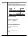
Table 3 Ethernet Driver File Names for the RC32xxx Processor Family
The Ethernet driver functions are listed below:
static int parse_mac_addr(struct net_device *dev, char* macstr)
Description:
Parse the MAC address
Parameter:
struct net_device *dev The pointer of the network device
char* macstr
The MAC address string
Return Value:
0
Succeed
1
Fail
static inline void [board name]_abort_tx(struct net_device *dev)
Description:
Abort the transmit DMA operation
Parameter:
struct net_device *dev The pointer of the network device
Return Value:
N/A
static inline void [board name]_abort_rx(struct net_device *dev)
Description:
Abort the receive DMA operation
Parameter:
struct net_device *dev The pointer of the network device
20 of 27
June 16, 2004
IDT Application Note AN-473
Notes
Return Value:
N/A
static inline void [board name]_halt_tx(struct net_device *dev)
Description:
Halt the transmit DMA operation
Parameter:
struct net_device *dev The pointer of the network device
Return Value:
N/A
static inline void [board name]_halt_rx(struct net_device *dev)
Description:
Halt the receive DMA operation
Parameter:
struct net_device *dev The pointer of the network device
Return Value:
N/A
static inline void [board name]_start_tx(struct [board name]_local *lp, volatile DMAD_t td)
Description:
Start the transmit DMA operation
Parameter:
struct [board name]_local *lpThe pointer of the Ethernet port
volatile DMAD_t td
The pointer of the transmit DMA descriptor
Return Value:
N/A
static inline void [board name]_start_rx(struct [board name]_local *lp, volatile DMAD_t rd)
Description:
Start the receive DMA operation
Parameter:
struct [board name]_local *lpThe pointer of the Ethernet port
volatile DMAD_t td The pointer of the receive DMA descriptor
Return Value:
N/A
static inline void [board name]_chain_tx(struct [board name]_local *lp, volatile DMAD_t td)
Description:
Chain the transmit DMA
Parameter:
struct [board name]_local *lpThe pointer of the Ethernet port
volatile DMAD_t td The pointer of the transmit DMA descriptor
Return Value:
21 of 27
June 16, 2004
IDT Application Note AN-473
Notes
N/A
static inline void [board name]_chain_rx(struct [board name]_local *lp, volatile DMAD_t rd)
Description:
Chain the receive DMA
Parameter:
struct [board name]_local *lpThe pointer of the Ethernet port
volatile DMAD_t td
The pointer of the receive DMA descriptor
Return Value:
N/A
static int [board name]_restart(struct net_device *dev)
Description:
Restart the network interface
Parameter:
struct net_device *dev The pointer of the network device
Return Value:
0
Succeed
Non-0
N/A
int [board name]_init_module(void)
Description:
Initiate the driver module
Parameter:
N/A
Return Value:
0
No device found
Non-0
At least one device found
static int [board name]_probe(int port_num)
Description:
Probe the Ethernet device.
Parameter:
int port_num
The Ethernet port number
Return Value:
0
Succeed
Non-0
Error
static int [board name]_open(struct net_device *dev)
Description:
Open the network device.
Parameter:
struct net_device *dev The pointer of the network device
Return Value:
22 of 27
June 16, 2004
IDT Application Note AN-473
Notes
0
Succeed
Non-0
Error
static int [board name]_close(struct net_device *dev)
Description:
Close the network device.
Parameter:
struct net_device *dev The pointer of the network device
Return Value:
0
Succeed
Non-0
Error
static int [board name]_send_packet(struct sk_buff *skb, struct net_device *dev)
Description:
Get the packet from the kernel, prepare the transmit DMA descriptors and start the
transmit DMA operation to send out this packet through the Ethernet port of the network device
Parameter:
struct sk_buff *skbSKB buffer pointer
struct net_device *dev The pointer of the network device
Return Value:
0
Succeed
1
Transmit queue is full
static void [board name]_mii_handler(unsigned long data)
Description:
Handle the Ethernet MII and PHY device
Parameter:
unsigned long dataData parameter for the MII device
Return Value:
N/A
static void [board name]_ovr_interrupt(int irq, void *dev_id, struct pt_regs * regs)
Description:
The interrupt handler for the Ethernet input FIFO overflow
Parameter:
int irq The IRQ number
void *dev_id
The device pointer
struct pt_regs * regsThe Pointer of the struct that defines the way the registers are stored on the stack
during a system call/exception. As usual the registers k0/k1 aren't being saved.
Return Value:
N/A
static void [board name]_und_interrupt(int irq, void *dev_id, struct pt_regs * regs)
Description:
The interrupt handler for the Ethernet output FIFO underflow
23 of 27
June 16, 2004
IDT Application Note AN-473
Notes
Parameter:
int irq The IRQ number
void *dev_id
The device pointer
struct pt_regs * regsThe Pointer of the struct that defines the way the registers are stored on the stack
during a system call/exception. As usual the registers k0/k1 aren't being saved.
Return Value:
N/A
static void [board name]_rx_dma_interrupt(int irq, void *dev_id, struct pt_regs * regs)
Description:
The interrupt handler for the receive DMA channel
Parameter:
int irq The IRQ number
void *dev_id
The device pointer
struct pt_regs * regsThe Pointer of the struct that defines the way the registers are stored on the stack
during a system call/exception. As usual the registers k0/k1 aren't being saved.
Return Value:
N/A
static void [board name]_rx_tasklet(unsigned long rx_data_dev)
Description:
The tasklet for the receive DMA channel
Parameter:
unsigned long rx_data_devData parameter for the receive tasklet
Return Value:
N/A
static void [board name]_tx_dma_interrupt(int irq, void *dev_id, struct pt_regs * regs)
Description:
The interrupt handler for the transmit DMA channel
Parameter:
int irq The IRQ number
void *dev_id
The Device pointer
struct pt_regs * regs The Pointer of the struct that defines the way the registers are stored on the
stack during a system call/exception. As usual the registers k0/k1 aren't being saved.
Return Value:
N/A
static void [board name]_tx_tasklet(unsigned long tx_data_dev)
Description:
The tasklet for the transmit DMA channel
Parameter:
unsigned long rx_data_dev The Data parameter for the transmit tasklet
Return Value:
24 of 27
June 16, 2004
IDT Application Note AN-473
Notes
N/A
static struct net_device_stats * [board name]_get_stats(struct net_device *dev)
Description:
Get the current statistics for the network device
Parameter:
struct net_device *dev The pointer of the network device
Return Value:
net_device_stats The pointer of the network device statistics
static void [board name]_multicast_list(struct net_device *dev)
Description:
Set or clear the multicast filter for the network device
Parameter:
struct net_device *dev The pointer of the network device
Return Value:
N/A
static void [board name]_tx_timeout(struct net_device *dev)
Description:
The transmit timeout handler
Parameter:
struct net_device *dev The pointer of the network device
Return Value:
N/A
static int [board name]_init(struct net_device *dev)
Description:
Initiate the network device
Parameter:
struct net_device *devThe pointer of the network device
Return Value:
0
Succeed
1
Fail
static void [board name]_cleanup_module(void)
Description:
Driver module clean up
Parameter:
N/A
Return Value:
N/A
25 of 27
June 16, 2004
IDT Application Note AN-473
Notes
static int __init [board name]_setup(char *options)
Description:
Setup the driver
Parameter:
char *options
The driver setup parameter
Return Value:
No option yet
static int __init [board name]_setup_ethaddr0(char *options)
Description:
Setup Ethernet port 0
Parameter:
char *options
The Ethernet port setup parameter
Return Value:
1
Always
static int __init [board name]_setup_ethaddr1(char *options)
Description:
Setup Ethernet port 1
Parameter:
char *options
The Ethernet port setup parameter
Return Value:
1
Always
module_init([board name]_init_module);
Description:
The driver module interface for initialization
Parameter:
[board name]_init_moduleThe description pointer for the driver module
Return Value:
N/A
module_exit([board name]_cleanup_module);
Description:
The driver module interface for exit
Parameter:
[board name]_init_moduleThe description pointer for the driver module
Return Value:
N/A
26 of 27
June 16, 2004
IDT Application Note AN-473
Notes
References
79RC32336 User Reference Manual
79RC32365 User Reference Manual
79RC32351 User Reference Manual
79RC32355 User Reference Manual
79RC32434 User Reference Manual
79RC32438 User Reference Manual
27 of 27
June 16, 2004