1
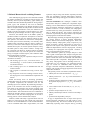
Table 2.
The set L of all concepts of a given formal context and
the partial order ≤ form a complete lattice, called concept
lattice:
O
L(C) = { ( O, A ) ∈ 2 × 2
A
A = σ(O) ∧ O = τ( A)}
The infimum of two concepts in this lattice is computed by intersecting their extents as follows:
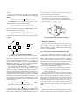
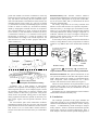
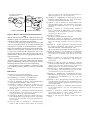
shown in Figure 2. The content of a node N in this representation can be derived as follows:
• the objects of N are all objects at and below N,
• the attributes of N are all attributes at and above N.
For instance, the node in Figure 2 marked with o2 and
a5 is the concept ({o2, o4}, {a3, a4, a5}).
( O 1, A 1 ) ∧ ( O 2, A 2 ) = ( O 1 ∩ O 2, σ ( O 1 ∩ O 2 ) )
The infimum describes a set of common attributes of
two sets of objects. Similarly, the supremum is determined by intersecting the intents:
a3, a4
a1, a2
o1
a5
o2
( O 1, A 1 ) ∨ ( O 2, A 2 ) = ( τ( A 1 ∩ A 2), A 1 ∩ A 2 )
The supremum ascertains the set of common objects,
which share all attributes in the intersection of two sets of
attributes.
C1
<
C6
4.1. Context for Scenarios and Subprograms
C7
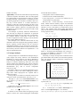
Figure 1. Concept lattice for Table 1.
The concept lattice for the example relation in Table 1
can be graphically depicted as a directed acyclic graph
whose nodes represent concepts and whose edges denote
the superconcept/subconcept relation < as shown in
Figure 1. The most general concept is called the top element and is denoted by . The most special concept is
called the bottom element and is denoted by ⊥ .
The combination of the graphical representation in
Figure 1 and the contents of the concepts in Table 2 form
the concept lattice. The complete information can be visualized in a more readable equivalent way by marking only
the graph node with an attribute a ∈ A whose represented
concept is the most general concept that has a in its intent.
Analogously, a node will be marked with an object o ∈ O
if it represents the most special concept that has o in its
extent. The unique element µ in the concept lattice marked
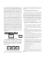
with a is therefore:
∨ { c ∈ L(C ) a ∈ intent ( c ) }
EQ (1)
∧ { c ∈ L(C ) o ∈ extent ( c ) }
EQ (2)
The unique element γ marked with object o is:
γ (o) =
Figure 2. Sparse representation of Figure 1.
In order to derive the feature-component map via concept analysis, one has to define the formal context
(objects, attributes, relation) and to interpret the resulting
concept lattice accordingly.
concept
C5
C4
µ(a) =
o4
4. Dynamic Analysis
C2
C3
a6, a7, a8
o3
We will call a graph representing a concept lattice
using this marking strategy a sparse representation of the
lattice. The equivalent sparse representation for Figure 1 is
The goal of the dynamic analysis is to find out which
subprograms contribute to a given set of features. For each
feature, a scenario is prepared that exploits this feature.
Hence, subprograms will be considered objects of the formal context, whereas scenarios will be considered
attributes. In the reverse case, the concept lattice is simply
inverted but the derived information will be the same.
The relation for the formal context necessary for concept analysis is thus defined as follows:
(s, S) ∈ R if and only if subprogram s is required
for scenario S; a subprogram is required when it
needs to be executed.
In order to obtain the relation, a set of scenarios needs
to be prepared where each scenario executes preferably
only one relevant feature. Then the system is used according to the set of scenarios, one at a time, and the execution
summaries are recorded. Each system run yields all
required subprograms for a single scenario, i.e., one column of the relation table can be filled per system run.
Applying all scenarios provides the complete relation
table.
4.2. On Features and Scenarios
Because one feature can be invoked by many scenarios
and one scenario can invoke several features, there is not