1
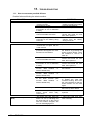
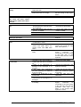
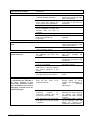
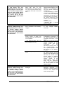
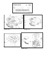
CT100 PEDESTRIAN SCRUBBER
DRYER
OPERATOR MANUAL
Clemas & Co. Unit 5 Ashchurch Business Centre, Alexandra Way, Tewkesbury,
Gloucestershire, GL20 8NB.
Tel: 01684 850777
Fax: 01684 850707
Email: [email protected]
Web: www.clemas.co.uk
ENGLISH
(Translation of original instructions)
1.
TABLE OF CONTENTS
1.
TABLE OF CONTENTS ....................................................................................................... 2
2.
GENERAL INFORMATION .................................................................................................. 4
2.1
2.2
2.3
3.
3.1
3.2
3.3
3.4
3.5
3.6
4.
4.1
5.
SCOPE OF THE MANUAL....................................................................................................... 4
IDENTIFICATION OF THE MACHINE......................................................................................... 5
DOCUMENTATION ANNEXED TO THE MACHINE ....................................................................... 5
TECHNICAL INFORMATION............................................................................................... 5
GENERAL DESCRIPTION ...................................................................................................... 5
LEGEND ............................................................................................................................. 5
DANGER AREAS .................................................................................................................. 6
SAFETY DEVICES ................................................................................................................ 6
OPTIONAL UNITS ................................................................................................................. 6
ACCESSORIES .................................................................................................................... 6
INFORMATION ON SAFETY ............................................................................................... 7
SAFETY STANDARDS ........................................................................................................... 7
HANDLING AND INSTALLATION ....................................................................................... 9
5.1
LIFTING AND CARRYING THE PACKED MACHINE ..................................................................... 9
5.2
CHECKING THE MACHINE ON DELIVERY ................................................................................ 9
5.3
UNPACKING ........................................................................................................................ 9
5.4
FEEDING BATTERIES ......................................................................................................... 10
5.4.1 Batteries: preparation................................................................................................. 10
5.4.2 Batteries: installation and connection......................................................................... 11
5.4.3 Batteries: removal ...................................................................................................... 11
5.5
THE BATTERY-CHARGER ................................................................................................... 12
5.5.1 Choosing the battery-charger..................................................................................... 12
5.5.2 Preparing the battery-charger .................................................................................... 12
5.6
LIFTING AND HANDLING THE MACHINE ................................................................................ 12
6.
PRACTICAL GUIDE FOR THE USER ............................................................................... 12
6.1
CONTROL DEVICES - DESCRIPTION .................................................................................... 12
6.2
INSTALLING AND ADJUSTING THE SQUEEGEE ...................................................................... 13
6.3
MOVING THE MACHINE ...................................................................................................... 14
6.4
INSTALLING AND REPLACING THE BRUSHES / DRIVE DISCS / ROLLERS ................................... 14
6.4.1 Brush head (models 60-70-80) .................................................................................. 14
6.4.2 Roller head (roller models R) ..................................................................................... 14
6.4.3 Flap adjustment.......................................................................................................... 15
6.5
DETERGENTS - USE .......................................................................................................... 15
6.6
SETTING UP THE MACHINE ................................................................................................. 15
6.7
W ORK .............................................................................................................................. 16
6.7.1.
Additional functions................................................................................................ 17
6.8
SOME USEFUL SUGGESTIONS FOR THE OPTIMAL USE OF THE MACHINE ................................ 17
6.8.1 Pre-washing ............................................................................................................... 17
6.8.2 Drying......................................................................................................................... 18
6.9
DRAINING OFF DIRTY WATER ............................................................................................. 18
6.10
DRAINING OFF CLEAN WATER ............................................................................................ 18
7.
PERIODS OF INACTIVITY................................................................................................. 19
8.
MAINTENANCE AND BATTERY RECHARGING ............................................................. 19
8.1
9.
RECHARGING PROCEDURES .............................................................................................. 19
INSTRUCTIONS FOR MAINTENANCE............................................................................. 20
9.1
MAINTENANCE – GENERAL RULES ..................................................................................... 20
9.2
ROUTINE MAINTENANCE .................................................................................................... 20
9.2.1 Precautions ................................................................................................................ 20
9.2.2 Suction air filter and floating rod: cleaning ................................................................. 20
9.2.3 Squeegee blades: check and replacement ................................................................ 20
2
ENGLISH
9.2.4 Fuses: replacement.................................................................................................... 21
9.3
PERIODIC MAINTENANCE ................................................................................................... 22
9.3.1 Daily maintenance...................................................................................................... 22
9.3.2 Weekly maintenance.................................................................................................. 22
9.3.3 Basket filter: cleaning ................................................................................................. 22
9.3.4 Six-monthly maintenance........................................................................................... 22
10.
HOW TO ORDER SPARE PARTS ................................................................................ 22
11.
TROUBLESHOOTING................................................................................................... 24
11.1.
HOW TO OVERCOME POSSIBLE FAILURES ........................................................................... 24
ENGLISH
3
2.
GENERAL INFORMATION
Read this manual carefully before starting any operations on this machine1.
2.1
Scope of the manual
This manual has been drawn up by the Manufacturer and is considered as an integral part
of the machine.
It defines the purpose for which the machine has been manufactured and contains all
information the operators2 require.
Besides this manual, which contains the necessary information for the users, other
publications have been issued, which contain the specific information for the technicians
in charge of maintenance3.
The constant observance of the instructions guarantee the safety of man and machine,
low running costs, quality results and a longer work life of the machine itself. The nonobservance of the prescribed rules could injure men, damage the machine, spoil the
washed floor and even the environment.
To find the single topics in a fast way, see the descriptive table of contents at the
beginning of this manual.
The paragraphs that are not to be neglected are printed in bold letters and preceded by
symbols illustrated and defined below.
! DANGER
Indicates that attention must be paid to avoid serious consequences that could
cause the death of the personnel or possible damages to health.
WARNING
Indicates that attention must be paid to avoid serious consequences that could
damage the machine, spoil the environment where the machine is used or cause
economic losses.
i INFORMATION
Particularly important instructions.
In following a policy of constant development and update of the product, the Manufacturer
could implement modifications without any previous notice.
Even though the machine you own is greatly different from the one(s) illustrated in this
manual, safety and information thereof are guaranteed anyway.
1 The definition "machine" substitutes the commercial name to which this manual refers.
2 People authorised to use the machine without carrying out maintenance operations that require precise technical
knowledge.
3 People having the experience, technical preparation and knowledge of the regulations and laws necessary to carry out
the activity and capable to recognize and avoid possible dangers when handling, installing, using the machine and
carrying out maintenance operations.
4
ENGLISH
2.2
Identification of the machine
The number plate (fig. 1), which is attached at the rear of the machine, shows the
following information:
• model code;
• machine model;
• power supply voltage;
• total rated power;
• serial number (registration number);
• year of manufacture;
• dry weight;
• maximum full load weight;
• steepest slope that can be overcome;
• bar code with serial number;
• Manufacturer’s identification.
2.3
•
•
•
•
•
Documentation annexed to the machine
User's Manual;
warranty certificate;
adhesive slips for spare part orders;
test sheet;
CE Certificate of conformity.
3.
3.1
TECHNICAL INFORMATION
General description
The machine is a sweeping scrubber, which can be used in civil and industrial
environments for sweeping, washing and drying flat, horizontal, smooth or moderately
rough floors, with even surfaces and free from obstacles.
The scrubber distributes on the floor an adequately dosed solution of water and
detergent, and brushes it to remove dirt. Choosing with care the right cleaning detergent
and brushes (or abrasive discs or roller) in the wide range of accessories available, the
machine can adapt itself to all kinds of combinations of floors and dirt.
A liquid suction system, which is embedded in the machine, allows a perfect drying of the
just-washed floor: actually thanks to a suction unit which sucks up the air from the
recovery tank thus creating a vacuum, the squeegee scrapes the dirty water from the
floor, collects it and sends it to the recovery tank.
The storage battery feeding and the high capacity of usable batteries allow the maximum
freedom of movement and endurance at any work conditions.
In addition, thanks to the electronic control drive motor provided with forward and reverse
gear, the floor can easily be cleaned in any direction.
3.2
Legend
The main components of the machine are the following (fig. 2):
• the detergent solution tank (fig. 2, ref. 3): used to contain and carry the mixture of clean
water and detergent;
• the recovery tank (fig. 2, ref. 2): used to collect dirty water sucked up from the floor
during washing;
• control panel (fig. 2, ref. 1);
• head unit (fig. 2, ref. 5): the main element is represented by the brushes/rollers, which
distribute the detergent solution on the floor, removing dirt;
• drive unit (fig. 2, ref. 7): the main element consists of the electronically controlled
gearmotor which is operated via a lever below the machine handgrip and enables the
machine to move forward and back;
ENGLISH
5
• squeegee unit (or floor wiper, fig. 2, ref. 8): used to wipe and dry the floor, sucking up
the water spread on the floor;
• battery unit (fig. 2, ref. 6): supplies energy for the machine feeding;
• bonnet (fig. 2, ref. 4).
3.3
Danger areas
A -Tank unit: in presence of certain detergents, danger of irritation for the eyes, skin,
mucous diaphragms, respiratory apparatus and asphyxia. Danger caused by dirt
recovered from the environment (germs and chemical subtances). Danger of crushing
between the recovery tank and solution tank, when the recovery tank is replaced on
the solution tank.
B -Control panel: danger of shortcircuits.
C -Lower part of washing head: danger due to lowering of head and rotation of
brushes/rollers.
D -Top of washing head: danger of crushing between the top of the brush head and the
chassis.
E -Rear wheels: danger of crushing between wheel, chassis and tank.
F - Electrical components box: danger of short circuits.
G -Battery compartment (located within the solution tank): danger of short circuits
between the battery poles and presence of hydrogen during battery charging.
3.4
Safety devices
A
B
-
C
3.5
DEVICE (fig. 3)
Emergency button
ACTIVATION
Made
active
when
pressed.
Safety in reverse
Safety device to prevent
crushing in reverse.
Cuts in when pressed.
Service brake
Comes on automatically
when the drive lever is
released.
Parking and emergency Press pedal C to
brake
engage.
Must
be
operated only with the
machine at a standstill
or
in
case
of
emergency: if operated
with
the
machine
moving, it can cause
damage.
FUCTION
Interrupts the power
supply.
Interrupts
reverse
movement of machine.
The machine gradually
decelerates.
Prevents the machine
moving.
Optional units
Hour counter: the hour counter accessory is fixed to the control panel (fig. 4, ref. 1). It
displays the number of brush operating hours.
3.6
•
•
•
•
6
Accessories
Bristle brushes/rollers: used for washing delicate floors and for polishing;
Polipropilene brushes/rollers: used for normal floor washing;
Tynex brushes/rollers: used to remove accumulated stubborn dirt on resistant floors;
Drive discs: allow the use of the following discs:
∗ yellow discs: used for washing and polishing marble and similar
surfaces;
∗ green discs: used for washing of resistant floors;
∗ black discs: used for thorough washing of resistant floors with
stubborn dirt.
ENGLISH
4.
4.1
INFORMATION ON SAFETY
Safety standards
Read the User's manual carefully before proceeding with start-up, use,
maintenance, routine maintenance or any other operations on the machine.
WARNING
Stick to all the instructions contained in this Manual (especially those regarding
danger and warning) and observe the safety plates attached on the machine.
The Manufacturer declines all responsibility for injures to persons or damage to
things deriving from the non-observance of these instructions.
The machine must be used by trained personnel only, who have shown their skill and
have been expressly authorized to use it.
Persons under eighteen cannot use the machine.
This machine must not be used for any other purpose than that for which it has been
expressly manufactured. Assess the type of building in which it will be used (e.g.
pharmaceutical and chemical companies, hospitals, etc.) and scrupulously respect the
regulations and conditions in force.
Do not use the machine in places that are not adequately lighted, in environments with
danger of explosions, on public roads, in the presence of dirt harmful to health or
improper environments.
The suitable temperature for the use of the machine ranges between +4°C and +35°C;
when the machine is not used, the temperature range is between +0°C e +50°C.
The humidity range for the machine under any conditions varies between 30% and 95%.
Never use or suck up inflammable or explosive liquids (e.g. petrol, fuel oil, etc.),
inflammable gases, dry dust, acids and solvents (e.g. solvents for paints, acetone, etc.)
even if diluted. Never suck up any burning or white-hot objects.
Do not use the machine on slopes or ramps higher than 2%; in the event of light slopes
do not use it transversally, handle it with extreme care and do not reverse. When driving
along ramps or heavier slopes take great care to avoid overturning or uncontrolled
acceleration. Overcome ramps and/or steps exclusively with the brush head and
squeegee lifted.
Never park the machine on slopes.
The machine must never be left unmanned with the motors running; before abandoning
the machine, switch the motors off, ensure that it cannot move accidentally, engage the
parking brake and remove the key from the ignition.
When using the machine mind the presence of people particularly children in the
environment where you are working.
Do not use the machine to carry persons/things or to tow things. Do not drag the
machine.
Never lay things on the machine for any reason.
Do not obstruct the air vents and heat dispersion openings.
Do not remove, modify or elude the safety devices.
Various and unpleasant experiences have shown that people wear or carry various
objects capable of causing serious accidents: before starting to work, remove trinkets,
watches, neckties or other such things.
Always use individual safety protections: apron or protective suit/overalls, non-slip waterproof shoes, rubber gloves, protective goggles and caps, face mask to protect the
respiratory system.
ENGLISH
7
Do not put the hands in between moving organs.
Do not use detergents different from those provided for, and stick to the instructions
indicated on the respective safety sheets. Keep detergents in a safe place, inaccessible
to children, and in case they come in contact with the eyes, wash them immediately with
plenty of water or, if swallowed, call for a doctor immediately.
Make sure that the plugs for the power supply of the models with cable or of the batterychargers are properly grounded and protected by magnetothermal switches and
differentials.
Make sure that the electric characteristics of the machine (voltage, frequency, absorbed
power) indicated on the identification plate (fig. 1), are compliant with those of the power
distribution plant. The machine with cable is equipped with three lead wires and a threecontact ground plug for the use of a proper grounding plug. The yellow and green wire of
the cable is the earth wire: never connect this wire to other wires that are not the plug
ground tap.
It is fundamental to observe the battery Manufacturer’s instructions and stick to the
Legislator’s provisions. Keep batteries always dry and clean to avoid surface leakage
currents. Keep batteries safe from impurities, for instance metal dust.
Do not lay tools on batteries: danger of short circuits and explosions.
Mind the use of battery acid: stick to the relative safety instructions.
When using the machine model with cable mind that you do not crush or tear the power
supply cable. Check this cable periodically to control if it is damaged; if this is so, the
machine cannot be used.
In presence of particularly high magnetic fields assess the possible effects on the control
electronics.
Never wash the machine with jets of water.
The recycled fluids contain detergents, disinfectants, water, organic and inorganic stuff
recycled during the work stages: they must be disposed of in compliance with the laws in
force.
In case of breakdown and/or bad operation of the machine, switch it off immediately
(unplugging it from the mains) and do not tamper with it. Contact a technical assistance
centre of the Manufacturer’s.
All maintenance operations must be performed in adequately lighted environments and
only after having disconnected the machine from the power supply (in models with cable
by unplugging the machine from the socket, while in models with battery by detaching the
battery connector).
Have any electrical work and all maintenance and repair operations (particularly those not
explicitely described in this manual) carried out a specialised and trained technical staff
only.
In case of replacement of the power supply cable, plug or terminals, perform the repair by
properly fixing the electric connections and the cable blocking strap that is located in the
control panel, to guarantee the resistance of the cable. Then reassemble the panel with
care to ensure the protection of the machine user.
Only the use of original accessories and spare parts supplied by the Manufacturer is
permitted, as only these offer the certainty that the machine will operate safely and
without any inconveniences. Do not use parts removed from other machines or other kits
as spares.
This product is classified as RAEE type special waste and is covered by the requisites of
the new environmental protection regulations (2002/96/CE RAEE). It must be disposed of
separately from ordinary waste in compliance with current legislation and standards.
Special waste. Do not dispose of with ordinary waste.
8
ENGLISH
Alternatively, the machine can be sent to the Manufacturer for a thorough overhaul.
If the machine is not used anymore, it is recommended that batteries are removed and
deposited at an authorized collecting centre.
Moreover, it is recommended that you make harmless those parts of the machine that
could be dangerous especially to children, who could use the machine for their games.
5.
5.1
HANDLING AND INSTALLATION
Lifting and carrying the packed machine
WARNING
In all lifting operations make sure that the packed machine has been tightly
anchored to the pallet, in order to avoid any overturning or accidental falls.
Loading and/or unloading from the motor vehicles must be performed in an
adequately lighted environment.
The machine, which is packed on a wooden pallet by the Manufacturer, must be loaded
by means of proper handling machines (refer to the EEC provision 89/392/CEE and
following amendments), onto the carrier and, once it has arrived at the appointed
destination, unloaded by similar means.
The brushes and the squeegees are packed in cardboard boxes without pallet.
The packed machine body must be lifted only with a fork lift truck. Handle with care to
avoid bumps or overturnings.
5.2
Checking the machine on delivery
On delivery check with attention that the package and the machine are not damaged. In
the event that the machine has suffered any damages, report so to the carrier; before
accepting the goods, reserve by written the right to present a claim for the refund of the
damages.
5.3
Unpacking
WARNING
On unpacking the machine, the operator must be provided with the necessary
accessories (e.g. gloves, protective goggles etc.) to limit possible hazards of
accidents.
Unpack the machine in the following way:
• cut and remove the plastic straps with scissors or nippers;
• remove the cardbox;
• remove the envelopes inside the battery compartment (within the solution tank) and
check its contents:
envelope 1: - test sheet;
- warranty coupon;
- user’s and maintenance manual;
envelope 2: - 3 battery bridge with clips;
- 1 pair of tweezers for fuses;
- 1 connector for the battery-charger;
- 2 switch keys;
i INFORMATION
Keep one of the 2 keys safe so that it can be located in case the other one is lost;
the other key is to be inserted in the lock on the mushroom switch.
• depending on the model, remove the metal brackets or cut the plastic straps, which fix
the machine chassis to the pallet;
ENGLISH
9
• disengage the parking brake via the pedal ref. C fig. 3;
• let the machine slide down the pallet on an inclined plane, by pushing it into reverse;
• unwrap the brushes/rollers (fig. 5, ref. 1) and the squeegee (fig. 5, ref. 2) from their
packing;
• clean the outside of the machine observing the safety rules;
• after unpacking the machine, you can install the batteries: see respective paragraphs.
If necessary, preserve the wrapping material as it could be used again to protect the
machine in the event of a move or if the machine should be sent to a service centre for
repair.
Otherwise, the material must be disposed of in compliance with the laws in force.
5.4
Feeding batteries
Two different batteries can be fitted on this machine:
•
Tubular leak-proof batteries: these batteries require the periodical check of the
electrolyte level. When it is necessary, top up with distilled water alone until the plates
are covered; do not overfill (max. 5 mm. above the plates).
• Gel batteries: this kind of batteries requires no maintenance.
When using this type of battery the fuse FU7 (fig. 6, ref. 2) inside the machine control
panel must be removed using the pliers. This operation serves to inform the electronic
control of the type of battery used.
WARNING
Do not fit the fuse FU7 if using gel batteries.
The technical specifications must correspond to those indicated in the paragraph
concerning the machine technical data: actually, the use of heavier storage batteries can
cause serious problems to the machine controllability and overheat the drive motor,
whereas storage batteries with a lower capacity require recharges more frequently.
They must be kept charged, dry and clean, with their connections tight.
5.4.1 Batteries: preparation
! DANGER
On installing or performing any kind of maintenance on the batteries wear the
necessary accessories (e.g. protective gloves, goggles, overalls, etc.) to limit the
hazards of accidents, keep away from possible free flames, do not short-circuit the
battery poles, cause sparks or smoke.
The batteries are normally supplied filled with acid and ready-for-use.
If batteries without acid are to be used, before mounting them on the machine, it is
necessary to make them active as follows:
• after taking off the battery plugs, fill up all elements with a solution of specific sulphuric
acid, until the cells are thoroughly covered (fill each element at least twice);
• let them rest for about 4-5 hours, to give time to air bubbles to come up to the surface
and the plates to absorb the electrolyte;
• check that the electrolyte level is still above the plates, otherwise top up with the
solution of sulphuric acid;
• reclose the plugs;
• install the storage batteries on the machine (following the procedure described below).
It is now necessary to perform a first recharging before having the machine start; to do so
stick to the instructions written in the respective paragraph.
10
ENGLISH
5.4.2 Batteries: installation and connection
! DANGER
Check that the emergency button on the control panel is at the position “0” (off).
Mind you connect only the clips marked with the symbol “+” to the positive poles.
Do not check the battery charge by creating sparkles.
Stick scrupulously to the instructions described below, as any short circuits of the
batteries may cause them to explode.
1) Stop the machine and press the emergency button (fig. 8, ref. 2); engage the parking
brake by means of the pedal (fig. 8, ref. 12);
2) make sure that the two tanks are empty (empty them, if necessary: see respective
paragraph);
3) unhook the recovery tank (fig. 2, ref. 2) from the solution tank (fig. 2, ref. 3) acting on
the blocking hook (fig. 7, ref. 1), placed on front of the machine;
4) lift the recovery tank, by making it turn backwards around about 90°: in this way you
have access to the battery compartment (embedded in the solution tank) from the
upper side;
WARNING
Before opening the upper tank:
ensure that the recovery tank is empty (an acoustic warning device will sound if
you try to open the recovery tank without emptying it first);
ensure that the emergency button is pressed.
5) insert the batteries in the compartment, orienting them as shown in the drawing printed
on the solution tank in the compartment.
WARNING
Install the storage batteries on the machine using suitable means according to
their weight.
Positive and negative poles have different diameters.
6) Referring to the arrangement of cables in the aforesaid drawing, connect the clips of
the battery wiring and the bridge to the poles of the storage batteries. After orienting
the cables as shown in the drawing, tighten the clips at the poles and cover them with
vaseline;
7) insert back the tank unit in its work position and hook it to the solution tank by means
of the fixing hook (fig. 7, ref. 1);
8) use the machine in compliance with the instructions written below.
5.4.3 Batteries: removal
! DANGER
When removing the batteries, the operator must be equipped with suitable personal
protection devices (gloves, goggles, overalls, safety shoes, etc) to reduce the risk
of accidents. Make sure the switches on the control panel are in the "0" position
(off) and the machine is turned off. Keep away from naked flames, do not short
circuit the battery poles, do not cause sparks and do not smoke. Proceed as
follows:
• disconnect the battery wiring and bridge terminals from the battery poles.
• if necessary, remove the devices fixing the battery to the base of the machine.
• lift the batteries from the compartment using suitable lifting equipment.
ENGLISH
11
5.5
The battery-charger
WARNING
Never let the batteries run down excessively, as they could become damaged
irreparably.
WARNING
Before recharging the batteries, ensure that you have pressed the emergency
button.
5.5.1 Choosing the battery-charger
Check that the battery-charger is compatible with the batteries to be charged:
− tubular lead batteries: an automatic battery-charger 24V - 20A is suggested. Anyway,
refer to the Manufacturer and read the relative manual to confirm your choice;
− gel batteries: use a battery-charger specifically intended for this type of storage
batteries.
5.5.2 Preparing the battery-charger
If you wish to use a battery-charger not supplied with the machine, it is necessary to
mount on it the connector delivered with the machine (see paragraph “Unpacking” of this
manual).
To install the connector proceed as follows:
• remove about 13 mm of sheath from the black and red cables of the battery-charger;
• insert the cables in the connector pins and push strongly with suitable pliers;
• insert the cables in the connector respecting the polarity (red cable +, black cable –).
5.6
Lifting and handling the machine
WARNING
All stages must be performed in an adequately lighted environment adopting all
necessary safety measures.
Always wear individual protections for the user’s safety.
The loading of the machine onto a vehicle must be done as follows:
• empty the recovery tank and the solution tank;
• remove the squeegee and the brushes (or drive discs);
• remove the batteries;
• place the machine on the pallet, engage the parking brake and secure it with plastic
straps or metal brackets;
• lift the pallet by means of a fork lift truck and load it on the vehicle;
• anchor the machine to the vehicle with ropes connected to the pallet and to the
chassis of the machine.
6.
6.1
PRACTICAL GUIDE FOR THE USER
Control devices - Description
With reference to fig. 8 the machine has the following controls and leds:
• Battery charge level indicator (ref. 9): signals both “Power on” and the battery
charge level. Note: the following percentages are based on the usable capacity and
not the total capacity of the batteries (therefore 100% flat = 80% of total battery
capacity). Possible situations are:
a) off: the main switch is set to “0” (off) or the batteries are disconnected;
b) green light: batteries charged from 100% to 50%;
c) yellow light: batteries charged from 50% to 15%;
d) red light (also simultaneously with yellow or green light): batteries flat and
12
ENGLISH
•
•
•
•
•
•
•
•
•
•
6.2
must be recharged.
Main switch - emergency button with key (ref. 2): enables or disables the power
supply to all the machine functions. It acts as a safety device. To start the machine
turn the proper key clockwise. To stop the machine press the button.
Brush/roller up-down button (ref. 5): when the arrow down is pressed, the head
moves down to the working position, the brush motor comes on automatically and the
solenoid valve is activated. Via this button, a variable pressure can be exerted on the
head during the work phase (according to how long the button is kept pressed), thus
adapting the cleaning power of the brushes to a wide range of different operating
conditions.
When the arrow up is pressed, the head moves up to the rest position, the brush
motors are switched off and the solenoid valve is de-activated.
Brush pressure indicator (ref. 8): indicates connections of brushes and pressure
exerted by the head (1 led on indicates beginning of brush connection; 2 leds on
indicate minimum pressure; 3 leds on indicate maximum pressure).
Brush release button (ref. 4): permits release of the brushes; press the button for a
couple of seconds: when the button is released, the brushes will be released.
Cock control lever (ref. 3): allows to adjust continuously the flow of solution sent to
the brushes. On turning it forward, the liquid outlet flow is increased.
Drive command lever (ref. 6): placed under the handgrip, when it is slightly pressed
upwards (the emergency button must be active), it starts the drive motor thus making
the machine move forward. When the lever is pressed down, the drive motor moves
the machine in reverse gear.
Squeegee lifting lever (ref. 11): it allows to raise (when lifted) or lower (when pushed
down) the squeegee. When it is pressed down, the suction motor is also switched on
for drying the floor.
Hour meter (ref. 7 - optional): displays the hours of work of the brush.
Parking brake pedal (ref. 12): engages (when pressed and moved to the right) and
disengages (when pressed and moved to the left) the parking brake.
Potentiometer (ref. 1): permits adjustment of the machine forward and reverse
speed; when the knob is turned clockwise the speed is increased.
Installing and adjusting the squeegee
The floor wiper, also called squeegee (fig. 2, ref. 8), is the first responsible for drying.
To install the squeegee on the machine proceed as follows:
1) Stop the machine and press the emergency button (fig. 8, ref. 2); engage the parking
brake by means of the pedal (fig. 9, ref. 5);
2) check that the squeegee supporting plate (fig. 9, ref. 2) is raised, otherwise lift it by
acting on the proper lever (fig. 9, ref. 6);
3) firmly push down the sleeve of the suction tube (fig. 9, ref. 4) into the squeegee;
4) slacken the two knobs (fig. 9, ref. 3) placed in the centre of the squeegee;
5) insert the two threaded dowels in the slots of the support (fig. 9, ref. 2);
6) fix the squeegee by tightening the knobs (fig. 9, ref. 3).
The blades of the squeegee are used to scrub from the floor the film of water and
detergent thus allowing a perfect drying. As long as time goes by the continuous scraping
rounds off and splits the sharp edge in contact with the floor, thus reducing the drying
efficacy and therefore requiring the replacement of the blades. Therefore, often check
their state of wear and tear.
To obtain a perfect drying action it is necessary to adjust the squeegee in such a way that
when it is in operation, the rear blade lip is bent about 45 degrees with respect to the floor
at all points. It is possible to adjust the inclination of the blades by screwing down the nuts
(fig. 9, ref. 1): by unscrewing the nuts the blade inclination is reduced, while by screwing
the nuts the blade inclination is increased.
Moreover, check that the suction hole of the squeegee is not clogged, to let dirty water to
ENGLISH
13
be perfectly drained from the floor.
6.3
Moving the machine
To displace the machine do as follows:
• lift the squeegee;
• raise the head by pressing the brush up-down button (fig. 8, ref. 5) on the arrow up;
• disengage the parking brake via the pedal (fig. 8, ref. 12);
• insert the key to release the emergency button (fig. 8, ref. 2);
• below the handgrip is a lever (fig. 8, ref. 6): by pulling the lever up (fig. 10, ref. 2) or
pressing it down (fig. 10, ref. 1), according to whether you wish to move forward or
back, the drive motor is switched on and the machine will begin to move;
• adjust the running speed via the potentiometer (fig. 8, ref. 1);
• once you have reached your destination, engage the parking brake via the pedal (fig.
8, ref. 12).
WARNING
Never leave the machine unmanned or parked with the parking brake disengaged
or the key inserted in the emergency button. Do not engage the parking brake when
the machine is moving.
6.4
Installing and replacing the brushes / drive discs / rollers
WARNING
Do not work if the brushes or drive discs are not perfectly installed.
6.4.1 Brush head (models 60-70-80)
Removing:
• raise the head by pressing the brush up-down button (fig. 8, ref. 5) on the arrow up;
• press the brush release button (fig. 8, ref. 4) for a couple of seconds: when the button
is released, the brushes will be released.
Fitting:
• position the brushes side by side at the front of the machine;
• move forward with the machine until the head is positioned above the brushes and
they are centred;
• press the brush up-down button (fig. 8, ref. 5) on the arrow down and keep it pressed
until the second led of the brush pressure indicator comes on (fig. 8, ref. 8); in this
phase the brush motor may come on and then switch off for a few moments: this is a
normal part of the brush engagement procedure.
WARNING
In particular conditions, the brushes may not engage correctly. In this case the
head will vibrate. The brushes must be disassembled and refitted.
If you wish to use the ABRASIVE DISCS instead of the brushes, they must firstly be fitted
on the drive discs: rest the pad on the drive disc, placing it exactly in the centre, and fix it
with the center lock ring nut. The drive discs must then be fitted on the machine following
exactly the same procedure as for the brushes.
WARNING
Fully tighten the drive disc flange via the handle provided in order to prevent the
flange dragging on the ground and damaging the floor.
6.4.2 Roller head (roller models R)
Disassembly:
• press the roller extraction buttons (fig. 11, ref. 4);
14
ENGLISH
• slide the rollers out (fig. 11, ref. 3).
Assembly:
• insert the cover drive element (fig. 11, ref. 2) on the roller (fig. 11, ref. 3);
• slide the roller below the head, keeping it slanting upwards by means of the cover
previously inserted. If the roller does not couple perfectly with the other drive element
(fig. 11, ref. 5) it must be rotated to permit connection. For the position of the roller
and direction of the bristles, refer to the label in fig. 12;
• press the roller extraction button (fig. 11, ref. 4);
• push the cover upwards and release the button.
6.4.3 Flap adjustment
• Loosen the screws (fig. 13, ref. 1);
• position the flap blade (fig. 13, ref. 2) so that it adheres perfectly to the floor;
• retighten the screws.
6.5
Detergents - Use
WARNING
Always dilute detergents according to the supplier’s instructions. Do not use
sodium hypochlorite (bleaching solution) or other oxidizers, especially if in high
concentrations, and do not use solvents or hydrocarbons. The temperatures for
water and detergent must not exceed the maximum temperatures indicated in the
technical data and must be free from sand and/or other impurities.
The machine has been designed to be used with non-foaming and biodegradable
detergents specific for sweeping scrubbers.
Contact the Manufacturer to have a complete and updated list of the available detergents
and chemical products; you will receive all papers together with the Manual “Complete
cleaning system”.
Use only products suitable for floors and for removing dirt.
Follow the safety rules concerning the use of detergents indicated in the paragraph
“Safety regulations”.
6.6
Setting up the machine
WARNING
Before starting to work wear an apron, cap, non-slip waterproof shoes, a mask to
protect the respiratory system, gloves and any other form of protection indicated
by the supplier of the detergent or necessary in the environment you are going to
work in.
Before starting to work, perform the following operations:
• check the level of battery charge (recharge, if necessary);
• disengage the parking brake via the pedal (fig. 8, ref. 12);
• make sure that the recovery tank (fig. 2, ref. 2) is empty; if this is not so, empty it;
• check that the cock control lever (fig. 8, ref. 3) is at the position “off”;
• fill the solution tank (fig. 2, ref. 3) through the respective hole on the front with clean
water and non-foaming detergent in a suitable concentration: leave a difference in level
of at least 5 cm between the liquid surface and the tank opening;
• install brushes or drive discs suitable for the floor and the job to be done;
• lower the head by pressing the brush up-down button (fig. 8, ref. 5) on the arrow down;
• check that the squeegee (fig. 2, ref. 8) is fixed well and connected to the suction tube
(fig. 9, ref. 4); make sure that the rear blade is not worn.
i INFORMATION
If you use the machine for the first time, it is advisable that you train with it for a
short time on a wide surface without any obstacles, to acquire the necessary
ENGLISH
15
familiarity.
Always empty the recovery tank before refilling the solution tank.
For an effective cleaning and long life of the equipment, it is necessary to follow some
simple rules:
• prepare the work area, keeping away the possible obstacles;
• begin to work starting from the farthest spot, in order to avoid trampling on the area
just-cleaned;
• choose paths that are as much straight as possible;
• on wide floors divide the paths into rectangular and parallel areas.
At the end quickly mop the area, if necessary, to clean spots that are inaccessible to the
scrubber.
6.7
Work
After setting up the machine, proceed as follows:
• insert and operate the key to release the main switch (fig. 8, ref. 2) and enable all the
machine functions: the battery charge level indicator will come on (fig. 8, ref. 9);
• move the cock lever (fig. 8, ref. 3) to the position of minimum flow of solution: the
detergent solution begins to reach the brushes;
• press the brush/roller up-down button (fig. 8, ref. 5) on the arrow down: the head will
begin to move down and as soon as the brushes touch the floor the brush motors will
come on. As the brushes rotate, the solution is distributed over the floor;
• lower the squeegee by means of the proper lever (fig. 8, ref. 11): the suction motor
comes on;
• press the drive lever (fig. 8, ref. 6) placed under the handgrip: the drive motor is started
and the machine starts moving forward;
• adjust the running speed via the potentiometer (fig. 8, ref. 1);
• if you wish to engage reverse gear during work with the squeegee lowered, you must
first stop and raise the squeegee;
• check periodically that the detergent solution reaches the brushes/rollers and fill with
solution if it runs out;
• check cleaning quality during work and adjust, as required, the flow of solution sent to
the brushes/rollers (by rotating the cursor (fig. 8, ref. 3)) and the pressure exerted by
the head-brushes on the floor (via the brush up-down button (fig. 8, ref. 5) until the test
pressure indicator (fig. 8, ref. 8) indicates the required level).
i INFORMATION
In working conditions, if the emergency switch is accidentally pressed and the
machine is switched off, when it is switched on again the brush button must be
pressed to re-activate the brushes.
WARNING
Never leave the machine stationary with the head lowered and the brushes in
motion: the floor could be damaged.
WARNING
Whenever you fill up the solution tank, always empty the recovery tank.
Do not leave the machine stationary with the suction motor on and the solution
cock turned on.
• if the warning led (fig. 8, ref. 9) starts flashing, it means that the storage batteries are
getting flat. Therefore, it is necessary to recharge them; if you keep on working, the
batteries could become damaged irreparably;
• if the suction unit revs up but does not perform suction, it means that the floater has
cut in. In this case the recovery tank must be emptied (see specific paragraph).
16
ENGLISH
WARNING
If for any reason the battery voltage drops considerably below the level envisaged,
even temporarily, the drive lock may cut in. In this case the machine must be
switched off and then on again.
At the end of work:
• move the cock lever (fig. 8, ref. 3) to the position “CLOSED”;
• release the drive lever (fig. 8, ref. 6) placed beneath the handle: the drive motor
switches off and the machine stops;
• raise the head by pressing the brush up-down button (fig. 8, ref. 5) on the arrow up to
stop the brushes (or drive discs or rollers) and raise them to prevent them becoming
permanently distorted;
• let the suction motor run for at least 2 minutes to make sure that it is completely dry;
• by raising the lever (fig. 8, ref. 11), lift the squeegee from the ground to prevent
continuous pressure causing distortion of the drying blades and to switch off the
suction motor;
• press the main switch (fig. 8, ref. 2) to disable all the machine functions;
• engage the parking brake via the pedal (fig. 8, ref. 12);
• empty and clean the recovery tank.
6.7.1. Additional functions
The machine is provided with additional functions that can be activated by removing
some fuses inside the control panel (fig. 14).
FU6 FUSE FUNCTION
When fuse FU6 is removed, the electronic control of the head is enabled, in particular the
following functions:
a) Brush timer: if the drive is released, the brushes will stop after a few seconds; to
reactivate the brushes, simply pull the drive lever.
b) Battery protection: when the batteries are flat, first the red led comes on, then the
brushes lock; in this case a continuous buzzer reminds the user that the head must be
raised to prevent damage to the brushes, since the drive continues to operate. The
brush motors are re-enabled by reset of the key (fig. 8, ref. 2) if the batteries have
sufficient load and voltage.
FU7 FUSE FUNCTION
Gel battery activation (the discharge voltages are varied for operation with the gel
batteries).
FU8 FUSE FUNCTION
Water is delivered to the brushes only when the drive is activated.
6.8
Some useful suggestions for the optimal use of the machine
If the floor presents a particularly resistant type of dirt, it is possible to make the machine
wash and dry it in separate stages.
6.8.1 Pre-washing
• Turn on the water cock;
• switch on the brush motor and lower the head;
• adjust the head pressure, which depends on the type of floor and dirt to be removed;
• start washing with the suction motor off and the squeegee lifted.
The flow of water must be dosed in proportion to the desired advance speed: the slower
the machine goes, less water comes down.
Insist on washing the dirtiest spots: in this way the detergent has the time to perform its
chemical action for the detachment and suspension of dirt, and the brushes to develop an
effective mechanical action.
ENGLISH
17
6.8.2 Drying
Lower the squeegee and with the suction unit operating pass again on the same area you
have previously washed. In this way you obtain a result that is similar to a thorough
washing and the following operations of ordinary maintenance will certainly take less time.
To wash and dry at the same time, operate the brushes, water, squeegee and suction
motor simultaneously.
WARNING
Never leave the machine unmanned with the suction unit running.
6.9
Draining off dirty water
! DANGER
Use the individual protection devices suitable for the operation to be performed.
Perform the draining operations with the machine disconnected from the power
supply.
The drain hose of the recovery tank is located at the rear left side of the machine.
To empty the above-mentioned tank:
• take the machine next to a drain;
• stop the machine and press the emergency button (fig. 8, ref. 2); engage the parking
brake by means of the pedal (fig. 8, ref. 12);
• take off the tank cap (fig. 15, ref. 1) from the recovery tank (fig. 15, ref. 5);
• detach the drain hose (fig. 15, ref. 2) from its seat, holding it in correspondence with
the fixing spring (fig. 15, ref. 3) and pull it horizontally;
• keeping the hose end as much high as possible, take off the drain cock (fig. 15, ref. 4)
from the hose by unscrewing it;
• lower the hose end gradually, checking the intensity of the jet of water with reference
to its height from the ground;
• check the amount of residual dirt in the recovery tank and wash it inside, if necessary.
To facilitate the cleaning and total drain, it is better to unhook it from the solution tank
and lift it;
• when the dirty water has been totally drained, lower the recovery tank (if it has been
previously lifted) and hook it again to the solution tank;
• put back the cap (fig. 15, ref. 1) on the recovery tank, making sure that it is perfectly
closed;
• close the drain hose (fig. 15, ref. 2) with the cock (fig. 15, ref. 4) screw-tightening it;
check that it is perfectly closed and refit the hose in its housing.
WARNING
While washing the recovery tank never remove the suction filter (fig. 18, ref. 2) from
its seat and never direct the jet of water towards the filter itself.
Now it is possible to proceed with a new washing and drying action.
6.10
Draining off clean water
! DANGER
Use the individual protection devices suitable for the operation to be performed.
Perform the draining off operations with the machine disconnected from the power
supply.
To empty the tank:
• take the machine next to a drain;
• stop the machine and press the emergency button (fig. 8, ref. 2); engage the parking
brake by means of the pedal (fig. 8, ref. 12);
18
ENGLISH
• detach the drain hose (fig. 16, ref. 1) from its seat, holding it in correspondence with
the fixing spring (fig. 16, ref. 2) and pull it horizontally;
• keeping the hose end as much high as possible, take off the drain cock (fig. 16, ref. 3)
from the hose by unscrewing it;
• lower the hose end gradually, checking the intensity of the jet of water with reference
to its height from the ground;
• when the contents have been totally drained from the solution tank, close the drain
hose with the cock (fig. 16, ref. 3) screw-tightening it; check that it is perfectly closed
and refit the hose in its housing.
i INFORMATION
The water and detergent solution can also be used to wash the recovery tank.
7.
PERIODS OF INACTIVITY
If the machine is to remain unused for a long time, the squeegee and brushes (or drive
discs or rollers) must be dismounted, washed and kept in a dry place (preferably packed
in a plastic envelope or sheet), sheltered from dust. Park the machine with the parking
brake engaged.
Furthermore, make sure that the tanks are completely empty and perfectly clean.
Recharge the batteries completely before putting them in the storehouse. During long
periods of inactivity recharge the batteries (once every two months at least) to preserve
the storage batteries constantly at the maximum charge.
WARNING
If the batteries are not recharged periodically, they may become damaged
irreparably.
8.
MAINTENANCE AND BATTERY RECHARGING
! DANGER
Do not check the battery charge by producing sparks.
The batteries give off inflammable vapours: put out any fire or embers before
checking and filling up the batteries.
Perform the operations described below in airy environments.
To avoid permanent damages to the batteries, never let them get flat completely.
Remember that when the proper red led (fig. 8, ref. 9) flashes on the control panel, it is
necessary to recharge the batteries.
8.1
Recharging procedures
Lead batteries with liquid electrolyte:
It is necessary to check the level of the electrolytic solution in order that it always covers
the films of the elements, adding the necessary distilled water.
WARNING
During recharging do not let the temperature of the electrolyte exceed 45°C.
To recharge proceed as follows:
• stop the machine and press the emergency button (fig. 8, ref. 2);
• engage the parking brake by means of the pedal (fig. 8, ref. 12);
• connect the battery-charger to the battery wiring connector (fig 17, ref. 1);
• recharge according to the instructions written in the manual to the battery-charger;
• switch off the battery charger before disconnecting the connectors;
ENGLISH
19
•
•
disconnect the battery charger connector from the battery wiring connector;
at the end of the recharging time check the battery intensity with a densimeter: if one
or more elements are flat and the remaining ones completely charged, the battery is
damaged and must be replaced.
Gel batteries:
• connect the battery-charger connector to the battery wiring connector (fig 17, ref. 1);
WARNING
Use only a battery-charger that is specific for gel storage batteries.
recharge following the instructions written in the manual to the battery-charger;
at the end of the recharging time disconnect the connectors.
•
•
9.
INSTRUCTIONS FOR MAINTENANCE
! DANGER
All maintenance operations on the electric system and those not explicitly
described in this manual must only be performed by trained technical staff in
compliance with the safety regulations in force and recommendations stated in the
maintenance manual.
9.1
Maintenance – General rules
A regular maintenance performed according to the Manufacturer’s intructions guarantees
a better performance and endurance of the machine.
9.2
Routine maintenance
9.2.1 Precautions
When cleaning the machine always observe the following instructions:
• avoid using water cleaners, which could let water go inside the electric or the motor
compartments with a consequent damage or hazard of short circuits;
• do not use steam in order not to warp the plastic parts;
• do not use solvents or hydrocarbons, which could damage the hoods or the rubber
parts.
i INFORMATION
Do not use water on the motors or electric parts.
9.2.2 Suction air filter and floating rod: cleaning
• Stop the machine and press the emergency button (fig. 8, ref. 2); engage the parking
brake by means of the pedal (fig. 8, ref. 12);
• unscrew and take off the tank cap (fig. 18, ref. 1) from the recovery tank (fig. 18, ref. 4);
• make sure that the recovery tank (fig. 18, ref. 4) is empty;
• take out the air filter (fig. 18, ref. 2) of the suction unit from the float support (fig. 18,
ref. 3), which is located on the upper inner side of the recovery tank;
• clean the filter with current water or with the detergent used in the machine;
• put the filter back in the support only after having it dried well;
• make sure that the filter has been replaced in its seat correctly;
• check that the floating rod (fig. 18, ref. 5), which is also fixed to the support (fig. 18, ref.
3), moves freely and clean it, if necessary;
• screw again the cap on the recovery tank.
9.2.3 Squeegee blades: check and replacement
The blades of the squeegee are used to scrub from the floor the film of water and
20
ENGLISH
detergent thus allowing a perfect drying. As long as time goes by the continuous scraping
rounds off and splits the sharp edge in contact with the floor, thus reducing the drying
efficacy and therefore requiring the replacement of the blades. Therefore, often check
their state of wear and tear.
Exchanging or replacing the blades:
• stop the machine and press the emergency button (fig. 8, ref. 2); engage the parking
brake by means of the pedal (fig. 8, ref. 12);
• lower the squeegee by using the proper lever (fig. 8, ref. 11);
• take off the squeegee (fig. 2, ref. 8) from its supporting plate (fig. 9, ref. 2) by
unscrewing completely the two knobs (fig. 9, ref. 3);
• slide out the sleeve of the suction tube (fig. 9, ref. 4) from the squeegee.
Front blade:
• unscrew the knobs (fig. 19, ref. 1);
• remove the blade clamps (fig. 19, ref. 3);
• take out the blade (fig. 19, ref. 4);
• fit in the same blade inverting the edge in contact with the floor until all the four edges
are worn, or else fit in a new blade;
• put the blade clamp (fig. 19, ref. 3) back;
• screw down all the knobs (fig. 19, ref. 1).
Rear blade:
• unhook the hook clamp (fig. 19, rif. 8);
• slide out the two blade clamps (fig. 19, ref. 7) by first pushing them outwards with
respect to the squeegee unit (fig. 19, ref. 5) and then taking them out;
• remove the blade (fig. 19, ref. 6);
• fit in the same blade inverting the edge in contact with the floor until all the four edges
are worn, or else fit in a new blade embedding it in the screws of the squeegee unit
(fig. 19, ref. 5);
• put the two blade clamps (fig. 19, ref. 7) back, centering the largest part of the slots on
the fixing screws of the squeegee unit (fig. 19, ref. 5) and then pushing the blade
clamps towards the inside of the squeegee itself;
• hook the clamp (fig. 19, ref. 8) again.
Insert the squeegee back on its support following the instructions reported in §6.2.
9.2.4 Fuses: replacement
To replace the fuses in the control panel of the machine, proceed as follows:
• stop the machine and press the emergency button (fig. 8, ref. 2); engage the parking
brake by means of the pedal (fig. 8, ref. 12);
• remove the fuse cover (fig. 20, ref. 1);
• with the tweezers supplied with the machine take out the blown fuses and replace
them with new ones of the same amperage;
• reclose the fuse cover.
WARNING
The fuse FU7 must NOT be fitted if the machine is provided with gel batteries.
To replace the fuses inside the electrical box, proceed as follows:
• stop the machine and press the emergency button (fig. 8, ref. 2); engage the parking
brake by means of the pedal (fig. 8, ref. 12);
• remove the bonnet (fig. 2, ref. 4);
• remove the cover of the electrical box (fig. 21, ref. 1);
• with the tweezers supplied with the machine take out the blown fuses and replace
them with new ones of the same amperage;
• re-close the cover of the electrical box;
ENGLISH
21
• refit the bonnet.
FUSE
DESCRIPTION
FUSE
DESCRIPTION
General fuse of power
Brush electronic control switch
FU1
FU6
Suction motor fuse
Switch for gel batteries
FU4
FU7
Control protection fuse
Solenoid valve control switch
FU5
FU8
Fuse chart: for a chart of the fuses see the Catalogue of Spare Parts.
WARNING
Never fit a fuse with a higher Amp value than the intended one.
If a fuse keeps burning, it is necessary to identify and repair the damages present in the
wiring, boards (if fitted) or motors: have the machine checked by trained technical staff.
9.3
Periodic maintenance
9.3.1
Daily maintenance
Every day at the end of work perform the following operations:
• stop the machine and press the emergency button (fig. 8, ref. 2);
• engage the parking brake by means of the pedal (fig. 8, ref. 12);
• empty the recovery tank and clean it, if necessary;
• clean the squeegee blades, checking that they are not excessively worn; replace them,
if necessary;
• make sure that the squeegee suction hole is not clogged, freeing it from any encrusted
dirt;
• recharge the batteries according to the procedure described above.
9.3.2
Weekly maintenance
• Clean the floating rod of the recovery tank and check that it works correctly;
• clean the suction air filter and check that it is not damaged (replace it, if necessary);
• clean the solution filter placed at the front opening of the solution tank (fig. 2, ref. 3)
and check that it is not damaged (replace it, if necessary);
• clean the suction tube;
• clean the recovery tank and the solution tank;
• check the level of the electrolyte in the batteries and top up with distilled water, if
necessary.
9.3.3
Basket filter: cleaning
• Unhook the recovery tank (fig. 2, ref. 2) from the solution tank (fig. 2, ref. 3) acting on
the blocking hook (fig. 7, ref. 1), placed on front of the machine;
• lift the recovery tank, by making it turn backwards around about 90°;
• take out the basket filter located at the front of the machine;
• clean the filter under running water or with the detergent used in the machine;
• refit the filter in the support and ensure that you have correctly repositioned it;
• insert back the tank unit in its work position and hook it to the solution tank by means
of the fixing hook (fig. 7, ref. 1).
9.3.4
Six-monthly maintenance
• Have the electric system, calibrations checked by qualified staff;
• VERSION R, HEAD WITH ROLLERS: tension the belts according to the directions in
the specifications.
10.
HOW TO ORDER SPARE PARTS
For a correct identification by our After-sales Service Office of the spare part(s) you need
and, therefore, to help us serving you better, please fill in your orders with the following
22
ENGLISH
data:
• machine model;
• machine serial number on the identification plate (see fig. 1);
• chart of the list of spare parts in which the item and its reference number are found;
• code of the item to be found in the list of spare parts;
• amount ordered.
If you as for a replacement under warranty terms, the order must be completed with a
brief description of the fault.
ENGLISH
23
11.
TROUBLESHOOTING
11.1. How to overcome possible failures
Possible failures affecting the whole machine
FAILURES
The machine does not work
CAUSES
REMEDIES
the emergency button is
pressed or faulty
• the batteries are flat
•
the
battery
connector
microswitch is out of calibration
or faulty;
• the power fuse FU1 and/or the
control fuse FU5 have blown
• insert the key, turn and
release or replace the button
• recharge the batteries
• calibrate or replace
•
• the battery charger connector is
connected to the battery wiring
connector
• the machine has been switched
off and then on again with the
head lowered
• the brush motor thermal
protection has tripped: the motor
has become overheated
The brushes do not turn
• the power fuse FU1 and/or the
control fuse FU5 have blown
• the brush motor activation
microswitch is out of calibration
or faulty
• the batteries are flat (with
function FU6 enabled, i.e.
without related fuse)
• the drive is released (with
function FU6 enabled, i.e.
without related fuse)
• fault in the board permitting use
of the brush function (with
function FU6 enabled, i.e.
without related fuse)
• the head is in the rest position
• check the components (brush
motors, brush motor relay,
connectors)
Buzzer
alarm)
24
sound
(brush
ENGLISH
stop
• the brush stop with head low
alarm has cut in, indicating that
the head may be on the ground
with the brushes stopped, with
the risk of damaging them
• check and remove the
causes that made the fuse
blow, then replace it
• disconnect the battery
charger from the battery
wiring connector
• press the drive lever
• release the drive lever; raise
the brushes by pressing the
brush up-down button; leave
the machine to cool for at
least 45’
• check and remove the
causes that made the fuse
blow, then replace it
• check and remove the
causes that made the fuse
blow, then replace it
• raise the head and recharge
the batteries
• pull the drive lever
• temporarily insert fuse FU6
to bypass the card and
continue working, then have
the card replaced so that the
brush function can be used
again
• lower the head by pressing
the brush up-down button
• have the faulty component
replaced
• raise the head and then
lower normally
• the brushes or abrasive discs or
rollers are worn
• the pressure exercised by the
head on the floor is not right
• replace them
The brush keeps on turning
also when the main switch
and/or brush switch have been
pressed
• the brush relay is faulty
• have it replaced
The solution does not come
out
• the head is in the rest position
and therefore the solenoid valve
is not working
• the cock control lever is at the
position “CLOSED”
• the tap filter is dirty
• the solution tank is empty
• lower the head by pressing
the brush up-down button
The flow of solution keeps
coming to the brush
• the solenoid valve is dirty
• have the solenoid valve
cleaned
The suction motor does not
work
• the squeegee microswitch is out
of calibration or faulty
• the power fuse FU1 and/or the
control fuse FU5 and/or the
suction motor fuse FU4 have
blown
• the suction motor is not fed or is
faulty
• calibrate or replace
The machine does not wash
evenly
The squeegee does not clean
or suck well
• the edge of the rubber blades in
contact with the floor is rounded
off
• there is an obstruction or
damage in the squeegee or in
the tube
• the float has intervened
(recovery tank full), or is blocked
by dirt or broken
• there is an obstruction in the
suction tube
• the suction tube is not
connected to the squeegee or is
damaged
• the suction unit motor is not fed
or is faulty
• adjust the brush pressure on
the floor acting on the proper
button
• move the lever to the
position “OPEN”
• clean it
• fill it up
• check and remove the
causes that made the fuse
blow, then replace it
• check that the motor power
supply
connector
is
connected to the main wiring
in the right way; in the
second case have the motor
replaced
• replace the rubber blade
• remove the obstruction and
repair the damage
• empty the recovery tank or
make the necessary repairs
to the float
• free the tube from the
obstruction
• connect or repair the tube
• check that the motor power
supply
connector
is
connected to the main wiring
in the right way and that the
protection fuse has not
blown; in the second case
replace the motor
ENGLISH
25
Outflow of detergent water
from head is not uniform
•
water outlet
obstructed
holes
are
The drive is not working
• the power fuse FU1 and/or the
control fuse FU5 have blown
• the thermal protection of the
drive motor has tripped: the
motor has become overheated
• the potentiometer is faulty
• the anti-crushing microswitch is
out of calibration or faulty (the
machine does not work in
reverse);
• the parking brake is engaged
• check the components (drive
motor, drive control unit,
connectors)
The washing head does not go
down
• the fuse FU5 has blown
• the head descent actuator is
disconnected or broken
The batteries do not ensure the
normal work time
• the poles and charging clips of
the batteries are dirty and
oxydized
• the electrolyte level is low
• the battery-charger does not
work or is unsuitable
•
there
are
considerable
differences in density between
the various elements of the
battery
• the machine is working with a
too high pressure on the brush
The storage battery gets flat
too fast during use, although it
has been charged in the
correct way and when tested
with a densimeter at the end of
recharging, it turned out to be
uniformly charged
ENGLISH
• check and remove the
causes that made the fuse
blow, then replace it
• stop the machine and switch
it off, letting it cool down for
at least 45’
• replace it
• calibrate or replace
• release the brake
• have the faulty component
replaced
•
check and remove the
causes that made the fuse
blow, then replace it
• have the connection restored
or the actuator replaced
• clean and grease the poles
and clips, recharge the
batteries
• add distilled water topping up
all elements according to the
instructions
• see instructions relative to
the battery-charger
• replace the damaged battery
• reduce pressure on the
brush
• the storage battery is new and
does not give 100% of its
expected capacity
• it is necessary to “run-in” the
storage battery by 20-30
charges and discharges to
obtain
maximum
performance
• the machine is used at its
maximum
capacity
for
continuous periods and the
autonomy is not sufficient
• use, if possible, storage
batteries with larger capacity
or replace the storage
batteries with others already
charged
• add distilled water, topping
up all elements until the
plates are covered and
recharge the storage battery
• the electrolyte has evaporated
and does not cover the plates
completely
26
• clean holes
The storage battery gets flat
too fast during use, the
recharging with an electronic
battery-charger is too fast and
at the end the storage battery
gives the right voltage (about
2,14V for each empty element),
but it turns out to be not
uniformly charged when tested
with densimeter
• the storage battery, already
filled
with
acid
by
the
Manufacturer, has been stored
for a too long time before being
recharged and used for the first
time
• if the recharging with a
normal storage-charger is not
effective, it is necessary to
carry out a double recharging
consisting in:
- a slow recharging of about
10 hours with a current equal
to 1/10 of the rated capacity
expressed in 5 hours (ex.: for
a storage battery of 100Ah(5),
the current should be 10A,
realized by a manual batterycharger);
- one-hour pause;
- charging with a normal
battery-charger
After recharging with an
electronic battery-charger the
storage-battery does not show
the correct voltage (about
2,14V for each empty element)
and only one or few elements
turn out to be flat when tested
with densimeter
• the storage battery has not
been connected to the batterycharger
• connect the battery-charger
to
the
storage
battery
connector
• the battery-charger and the
power socket to which the
storage battery is connected are
not compatible
• check that the power supply
characteristics indicated on
the battery-charger plate are
compliant with those of the
mains
• taking into account the actual
voltage available at the
socket, check that the
connections
of
the
transformer primary circuit in
the
battery-charger
are
correct (at this purpose read
the manual to the batterycharger)
• check that there is voltage at
the battery-charger, that the
fuses are not interrupted and
that there is current at the
storage battery; in addition
try to charge by means of
another rectifier: if the
battery-charger does not
work, call the after-sales
service staff communicating
the serial number of the
battery-charger
• the battery-charger has not
been installed correctly
• the battery-charger does not
work
After recharging with an
electronic battery-charger the
storage-battery does not show
the correct voltage (about
2,14V for each empty element)
and only one or few elements
turn out to be flat when tested
with densimeter
• one or more elements are
damaged
• replace, if possible, the
damaged
elements.
For
monoblock storage batteries
at 6V or 12V, replace the
whole storage battery
ENGLISH
27
The electrolyte that is present
in the storage battery has a
cloudy colour
28
ENGLISH
• the storage battery has
completed the charge/discharge
cycles
indicated
by
the
Manufacturer
• the storage battery has been
recharged with a too high current
• the storage battery has been
charged
beyond
the
limit
suggested by the Manufacturer
• replace the storage battery
• replace the storage battery
• replace the storage battery
Fig./Abb./ Рис 1
Fig./Abb./ Рис 2
Fig./Abb./ Рис 3
Fig./Abb./ Рис 4
Fig./Abb./ Рис 5
Fig./Abb./ Рис 6
Fig./Abb./ Рис 7
Fig./Abb./ Рис 8
Fig./Abb./ Рис 9
Fig./Abb./ Рис 10
Fig./Abb./ Рис 11
Fig./Abb./ Рис 12
2
1
Fig./Abb./ Рис 13
Fig./Abb./ Рис 14
Fig./Abb./ Рис 16
Fig./Abb./ Рис 15
Fig./Abb./ Рис 17
Fig./Abb./ Рис 18
Fig./Abb./ Рис 19
Fig./Abb./ Рис 20
Fig./Abb./ Рис 21