1
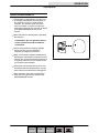
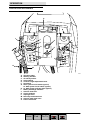
TENNANT 5680
SCRUBBER DRYER
OPERATOR MANUAL
Clemas & Co. Unit 5 Ashchurch Business Centre, Alexandra Way, Tewkesbury,
Gloucestershire, GL20 8NB.
Tel: 01684 850777
Fax: 01684 850707
Web: www.clemas.co.uk
Email: [email protected]
CONTENTS
CONTENTS
Page
SAFETY PRECAUTIONS . . . . . . . . . . . . . . . . . 3
OPERATION . . . . . . . . . . . . . . . . . . . . . . . . . . . .
OPERATOR RESPONSIBILITY . . . . . . . .
MACHINE COMPONENTS . . . . . . . . . . . .
CONTROL PANEL SYMBOLS . . . . . . . . .
CONTROLS AND INSTRUMENTS . . . . . .
STEERING HANDLES . . . . . . . . . . . . .
ON-OFF KEY SWITCH . . . . . . . . . . . .
SCRUB SWITCH . . . . . . . . . . . . . . . . .
SCRUB HEAD STRAP (DISC HEAD)
SQUEEGEE LEVER . . . . . . . . . . . . . . .
HOURMETER . . . . . . . . . . . . . . . . . . . .
BATTERY DISCHARGE INDICATOR
FaST SWITCH (OPTION) . . . . . . . . . .
ec--H2O SWITCH (OPTION) . . . . . . .
POWER KILL SWITCH . . . . . . . . . . . .
SOLUTION FLOW LEVER . . . . . . . . .
CIRCUIT BREAKERS . . . . . . . . . . . . .
SOLUTION TANK HOSE . . . . . . . . . . .
RECOVERY TANK DRAIN HOSE . . .
SUPPORT ARM . . . . . . . . . . . . . . . . . .
STOP ARM . . . . . . . . . . . . . . . . . . . . . .
SQUEEGEE DOWN PRESSURE
CAMS . . . . . . . . . . . . . . . . . . . . . . . . .
PARKING BRAKE . . . . . . . . . . . . . . . . .
HOW THE MACHINE WORKS . . . . . . . . .
FaST SCRUBBING SYSTEM
(OPTION) . . . . . . . . . . . . . . . . . . . . . .
ec--H2O SYSTEM (OPTION) . . . . . . .
PRE-OPERATION CHECKLIST . . . . . . . .
INSTALLING FaST PAK AGENT
(OPTION) . . . . . . . . . . . . . . . . . . . . . . .
STARTING THE MACHINE . . . . . . . . . . . .
FILLING THE TANKS . . . . . . . . . . . . . . . . .
SCRUBBING AND BRUSH
INFORMATION . . . . . . . . . . . . . . . . . . . . .
DOUBLE SCRUBBING . . . . . . . . . . . . . . . .
STOP SCRUBBING . . . . . . . . . . . . . . . . . . .
DRAINING AND CLEANING
THE TANKS . . . . . . . . . . . . . . . . . . . . . . . .
OPERATION ON INCLINES . . . . . . . . . . .
STOP THE MACHINE . . . . . . . . . . . . . . . . .
POST-OPERATION CHECKLIST . . . . . . .
MACHINE TROUBLESHOOTING . . . . . . .
MAINTENANCE . . . . . . . . . . . . . . . . . . . . . . . . .
MAINTENANCE CHART . . . . . . . . . . . . . . .
LUBRICATION . . . . . . . . . . . . . . . . . . . . . . .
REAR CASTERS . . . . . . . . . . . . . . . . .
TRANSAXLE . . . . . . . . . . . . . . . . . . . . .
BATTERIES . . . . . . . . . . . . . . . . . . . . . . . . .
CHARGING THE BATTERIES . . . . . .
ELECTRIC MOTORS . . . . . . . . . . . . . . . . .
5
5
6
7
8
9
10
11
11
11
12
12
12
13
13
14
14
15
15
15
16
16
16
17
18
19
20
21
23
23
25
29
30
31
35
35
36
37
39
39
41
41
41
41
43
44
Page
SCRUB HEAD . . . . . . . . . . . . . . . . . . . . . . . 45
DISK BRUSH SCRUB HEAD SKIRT . 45
CYLINDRICAL BRUSH SCRUB
HEAD SKIRTS . . . . . . . . . . . . . . . . . . 45
ADJUSTING THE SCRUB
HEAD SKIRTS . . . . . . . . . . . . . . . . . . 45
REPLACING THE SCRUB
HEAD SKIRTS . . . . . . . . . . . . . . . . . . 45
REMOVING OR REPLACING
THE SCRUB HEAD . . . . . . . . . . . . . . 46
LEVELING THE SCRUB HEAD . . . . . 49
SCRUB BRUSHES AND PADS . . . . . . . . . 50
DISK BRUSHES . . . . . . . . . . . . . . . . . . 50
REPLACING THE DISK BRUSHES
OR PADS . . . . . . . . . . . . . . . . . . . . . . 50
CYLINDRICAL BRUSHES . . . . . . . . . . 54
REPLACING THE CYLINDRICAL
BRUSHES . . . . . . . . . . . . . . . . . . . . . . 54
CHECKING AND ADJUSTING
CYLINDRICAL BRUSH PATTERN . . . . . . 55
SOLUTION SYSTEM . . . . . . . . . . . . . . . . . 57
RECOVERY TANK . . . . . . . . . . . . . . . . 57
SOLUTION TANK . . . . . . . . . . . . . . . . . 58
FaST SYSTEM (OPTION) . . . . . . . . . . . . . 59
FaST SYSTEM MAINTENANCE . . . . 59
FaST SYSTEM FILTER SCREEN . . . 60
FaST SUPPLY HOSE
CONNECTOR . . . . . . . . . . . . . . . . . . 60
ec--H2O SYSTEM (OPTION) . . . . . . . . . . . 61
ec--H2O MODULE FLUSH
PROCEDURE . . . . . . . . . . . . . . . . . . 61
SQUEEGEE . . . . . . . . . . . . . . . . . . . . . . . . . 62
REMOVING THE SQUEEGEE
ASSEMBLY . . . . . . . . . . . . . . . . . . . . . . . . . . 62
INSTALLING THE SQUEEGEE
ASSEMBLY . . . . . . . . . . . . . . . . . . . . . . . . . . 63
LEVELING THE SQUEEGEE . . . . . . . 63
ADJUSTING SQUEEGEE BLADE
DEFLECTION . . . . . . . . . . . . . . . . . . 64
SQUEEGEE BLADES . . . . . . . . . . . . . . . . . 65
REPLACING OR ROTATING THE
REAR SQUEEGEE BLADE . . . . . . . 65
REPLACING OR ROTATING THE
FRONT SQUEEGEE BLADE . . . . . 67
BELTS AND CHAINS . . . . . . . . . . . . . . . . . 68
BRUSH DRIVE BELT . . . . . . . . . . . . . . 68
STATIC DRAG CHAIN . . . . . . . . . . . . . 68
TIRES . . . . . . . . . . . . . . . . . . . . . . . . . . . . . . . 68
PUSHING AND TRANSPORTING
THE MACHINE . . . . . . . . . . . . . . . . . . . . . 69
PUSHING THE MACHINE . . . . . . . . . 69
TRANSPORTING THE MACHINE . . . 69
MACHINE JACKING . . . . . . . . . . . . . . . . . . 71
STORAGE INFORMATION . . . . . . . . . . . . 71
FREEZE PROTECTION . . . . . . . . . . . 71
1
5680 330459 (10--08)
Home
Find... Go To..
CONTENTS
Page
SPECIFICATIONS . . . . . . . . . . . . . . . . . . . . . . . 73
GENERAL MACHINE
DIMENSIONS/CAPACITIES . . . . . . . . . . . 73
FaST SYSTEM (OPTION) . . . . . . . . . . . . . 74
ec--H2O SYSTEM (OPTION) . . . . . . . . . . . 74
GENERAL MACHINE PERFORMANCE . 74
POWER TYPE . . . . . . . . . . . . . . . . . . . . . . . 75
TIRES . . . . . . . . . . . . . . . . . . . . . . . . . . . . . . . 75
MACHINE DIMENSIONS . . . . . . . . . . . . . . 76
2
5680 330459 (10--08)
Home
Find... Go To..
SAFETY PRECAUTIONS
SAFETY PRECAUTIONS
The following symbols are used throughout this
manual as indicated in their description:
WARNING: To warn of hazards or unsafe
practices that could result in severe
personal injury or death.
FOR SAFETY: To identify actions that
must be followed for safe operation of
equipment.
This machine is designed solely for scrubbing dirt
and dust in an indoor environment. Tennant does
not recommend using this machine in any other
environment.
The following information signals potentially
dangerous conditions to the operator or
equipment. Read this manual carefully. Know
when these conditions can exist. Locate all safety
devices on the machine. Then, take necessary
steps to train machine operating personnel.
Report machine damage or faulty operation
immediately. Do not use the machine if it is not in
proper operating condition.
WARNING: Batteries emit hydrogen gas.
Explosion or fire can result. Keep
sparks and open flame away. Keep
covers open when charging.
WARNING: Flammable materials can
cause an explosion or fire. Do not use
flammable materials in tank(s).
WARNING: Flammable materials or
reactive metals can cause an explosion
or fire. Do not pickup.
FOR SAFETY:
1. Do not operate machine:
-- Unless trained and authorized.
-- Unless operation manual is read and
understood.
-- In flammable or explosive areas unless
designed for use in those areas.
3. When using machine:
-- Go slow on inclines and slippery
surfaces.
-- Use care when backing machine.
-- Follow mixing and handling
instructions on chemical containers.
4. Before leaving or servicing machine:
-- Stop on level surface.
-- Set the parking brake.
-- Turn off machine and remove key.
5. When servicing machine:
-- Avoid moving parts. Do not wear loose
jackets, shirts, or sleeves when
working on machine.
-- Block machine tires before jacking
machine up.
-- Jack machine up at designated
locations only. Block machine up with
jack stands.
-- Use hoist or jack of that will support
the weight of the machine.
-- Wear eye and ear protection when
using pressurized air or water.
-- Disconnect battery connections before
working on machine.
-- Avoid contact with battery acid.
-- Wear protective gloves and eye
protection when handling white
vinegar.
-- Use Tennant supplied or equivalent
replacement parts.
6. When loading/unloading machine
onto/off truck or trailer:
-- Turn off machine.
-- Use truck or trailer that will support
the weight of the machine.
-- Use winch. Do not push the machine
onto/off the truck or trailer unless the
load height is 380 mm (15 in) or less
from the ground.
-- Set parking brake after machine is
loaded (option).
-- Block machine tires.
-- Tie machine down to truck or trailer.
2. Before starting machine:
-- Make sure all safety devices are in
place and operate properly.
-- Check brakes and steering for proper
operation (if so equipped).
3
5680 330459 (10--08)
Home
Find... Go To..
SAFETY PRECAUTIONS
The safety labels appear on the machine in the
locations indicated. If these or any label becomes
damaged or illegible, install a new label in its
place.
FLAMMABLE MATERIALS LABEL -LOCATED ON THE UNDERSIDE OF
THE SOLUTION TANK COVER.
FOR SAFETY LABEL -- LOCATED ON
THE OPERATOR CONSOLE.
353417
BATTERY CHARGING LABEL -- LOCATED ON
THE UNDERSIDE OF THE SOLUTION TANK.
4
FLAMMABLE SPILLS LABEL -- LOCATED
ON THE OPERATOR CONSOLE.
5680 330459 (10--00)
Home
Find... Go To..
OPERATION
OPERATION
OPERATOR RESPONSIBILITY
- The operator’s responsibility is to take care
of the daily maintenance and checkups of
the machine to keep it in good working
condition. The operator must inform the
service mechanic or supervisor when the
maintenance intervals are required as stated
in the MAINTENANCE section of this
manual.
- Read this manual carefully before operating
this machine.
FOR SAFETY: Do not operate machine,
unless operation manual is read and
understood.
- Check the machine for shipping damage.
Check to make sure the machine is
complete per shipping instructions.
- Keep your machine regularly maintained by
following the maintenance information in this
manual. We recommend taking advantage of
a regularly scheduled service contract from
your Tennant representative.
07324
- Order parts and supplies directly from your
authorized Tennant representative. Use the
parts manual provided when ordering parts.
- After operation, follow the recommended
daily and hourly procedures stated in the
MAINTENANCE CHART.
5
5680 330459 (10--00)
Home
Find... Go To..
OPERATION
MACHINE COMPONENTS
B
A
D
F
C
H
J
K
A
I
G
E
L
C
M
Q
M
N
O
P
A.
B.
C.
D.
E.
F.
G.
H.
I.
J.
K.
L.
M.
N.
O.
Solution tank
Solution tank fill opening
Recovery tank
Steering handles
Squeegee
Squeegee lever
Squeegee down pressure cams
Recovery tank drain hose
Solution tank hose
Support arm
Stop arm
Batteries
Scrub head
Scrub brush access cover
FaST solution system (option)
ec- H2O System Module (option)
P. Heavy duty scrub head strap
Q. Scrub brush idler door
6
5680 330459 (10--08)
Home
Find... Go To..
OPERATION
CONTROL PANEL SYMBOLS
These symbols identify controls and displays on
the machine:
Key switch
Circuit breaker #1--scrub head actuator
Variable flow or rate
Circuit breaker #2--vacuum fan motor
Solution flow
Circuit breaker #3--machine propel
Scrub brushes down and on
Circuit breaker #4--left brush motor
Scrub brushes up and off
Circuit breaker #5--right brush motor
Heavy scrub brush down pressure
Circuit breaker #6--FaST
Circuit breaker #6--ec--H2O
7
5680 330459 (10--08)
Home
Find... Go To..
OPERATION
CONTROLS AND INSTRUMENTS
A
B
B
J
F
O
C
H
G
E
I
D
CB4
CB5
K
CB6
CB1
K
CB2
CB3
L
N
M
A.
B.
C.
D.
E.
F.
G.
H.
I.
J.
K.
L.
M.
N.
O.
Operation label
Steering handles
On-off key switch
Scrub switch
Console height adjustment knob
Hourmeter
FaST system on/off switch (option)
ec- H2O system on/off switch (option)
ec- H2O system indicator light (option)
Battery discharge indicator
Solution flow lever
Circuit breakers
Squeegee lever
Recovery tank drain hose
Solution tank drain hose
Power Kill Switch
8
10345
5680 330459 (10--08)
Home
Find... Go To..
OPERATION
STEERING HANDLES
The steering handles control the machine speed
and direction.
Forward: Rotate the steering handles forward. The
further forward you rotate the steering handles,
the faster the machine will go.
Backward: Rotate the steering handles
backwards toward you.
Turning: Push the machine in the direction of the
turn with the steering handles. The machine will
turn on the swivel casters.
9
5680 330459 (10--00)
Home
Find... Go To..
OPERATION
Stop: Release the steering handles.
The steering console height is adjustable.
Adjust: Turn the console adjustment knob
counterclockwise to loosen the knob. Move the
console up or down to the desired height. Then
turn the knob clockwise to tighten the knob, and
lock the console in position.
ON-OFF KEY SWITCH
The on-off key switch controls machine power with
a key.
On: Turn the key to the right.
Off: Turn the key to the left.
10
5680 330459 (10--00)
Home
Find... Go To..
OPERATION
SCRUB SWITCH
The scrub switch controls the scrubbing
operations.
Lower brushes and start scrubbing: Press the top
of the switch.
Raise brushes and stop scrubbing: Press the
bottom of the switch.
NOTE: The scrub brushes do not start until the
steering handles are rotated forward or backward.
NOTE: The scrub switch also controls the
FaST/ec-H2O system (option) when the
FaST/ec-H2O system is enabled with the
FaST/ec-H2O switch.
SCRUB HEAD STRAP (DISC HEAD)
The scrub head strap increases the scrub head
pressure and puts the scrub head into heavy
scrub mode.
The heavy scrub mode is used when deep
scrubbing or floor stripping is necessary.
Start heavy scrub mode: With the scrub head in
the up position, pull out on the scrub head strap
until the scrub head drops into place. Lower the
brushes and start scrubbing.
Stop heavy scrub mode: Press the bottom of the
scrub switch. The scrub head will reset when it
raises and stops scrubbing. When it is started
again, the scrub head will operate at daily
scrubbing pressure.
SQUEEGEE LEVER
The squeegee lever controls the squeegee and
the vacuum system.
Lower squeegee and start vacuum: Move the
squeegee lever up and to the left to unlock it, and
then release the lever.
Raise squeegee and stop vacuum: Pull the lever
up and move it to the right to lock the lever in the
up position.
NOTE: Raise the squeegee before reversing the
machine.
11
5680 330459 (10--08)
Home
Find... Go To..
OPERATION
HOURMETER
The hourmeter records the number of hours the
machine has been powered on. This information is
useful when servicing the machine.
BATTERY DISCHARGE INDICATOR
The battery discharge indicator shows the charge
level of the batteries.
When the batteries are fully charged, the indicator
on the far right is lit. As the batteries discharge,
the indicator will move along the display to the left.
Recharge the batteries when the indicator flashes.
NOTE: The battery discharge indicator will not
reset from the flashing indicator unless the
batteries have been fully charged.
FaST SWITCH (OPTION)
The FaST switch (option) enables the FaST
(Foam Scrubbing Technology) system. When the
FaST system is enabled, it is turned on and off
with the scrub switch
Enable the FaST system: Press the top of the
FaST switch.
Enable conventional scrubbing: Press the bottom
of the FaST switch.
NOTE: Disable the FaST system before using the
machine for conventional scrubbing.
NOTE: The FaST system will not start until the
steering handles are rotated forward or backward.
NOTE: Do not enable the FaST system with
conventional cleaning detergents in the solution
tank. Drain, raise and refill the solution tank with
clear cool water only before operating the FaST
system. Conventional cleaning detergents/
restorers may cause failure to the FaST solution
system.
12
5680 330459 (3--08)
Home
Find... Go To..
OPERATION
ec- H2O SWITCH (OPTION)
The ec--H2O switch (option) enables the ec--H2O
(electrically converted water) system. When the
ec--H2O system is enabled, it is turned on and off
with the scrub switch.
Enable the ec--H2O system: Press the top of the
ec--H2O switch.
Enable conventional scrubbing: Press the bottom
of the ec--H2O switch.
NOTE: Disable the ec--H2O system before using
the machine for conventional scrubbing.
NOTE: The ec--H2O system will not start until the
machine starts scrubbing.
NOTE: Do not enable the ec--H2O system with
conventional cleaning detergents in the solution
tank. Drain, raise and refill the solution tank with
clear cool water only before operating the ec--H2O
system. Conventional cleaning detergents/
restorers may cause failure to the ec--H2O
solution system.
POWER KILL SWITCH
The power kill switch halts all power to the
machine.
Halt: Hit the power kill switch.
Restart: Turn the power kill switch to the right to
release the switch. Turn off the machine power,
then turn on the machine power.
13
5680 330459 (10--08)
Home
Find... Go To..
OPERATION
SOLUTION FLOW LEVER
The solution flow lever controls the amount of
solution flow to the floor.
Increase: Push the lever forward.
Decrease: Pull the lever backward.
NOTE: A solenoid valve dispenses the solution to
the scrub head. The valve opens when the
steering handles are rotated forward, and closes
when the steering handles are released in neutral
position.
NOTE: When using the FaST or ec--H2O system
(option), the solution flow lever is nonfunctional.
The FaST and ec--H2O system flow rates are
pre--set. The ec--H2O module has optional flow
rate settings. If solution flow adjustments are
required, contact an Authorized Service Center.
CIRCUIT BREAKERS
The circuit breakers are resettable electrical circuit
protection devices. They stop the flow of current in
the event of a circuit overload. Once a circuit
breaker is tripped, reset manually by pressing the
reset button after the breaker has cooled down.
If the overload that caused the circuit breaker to
trip is still there, the circuit breaker will continue to
stop current flow until the problem is corrected.
The circuit breakers are located on each side of
the operator console.
The chart shows the circuit breakers and the
electrical components they protect.
Circuit
Breaker
Rating
Circuit Protected
CB1
10 A
Machine power
CB2
25 A
Vacuum fan motor
CB3
25 A
Machine propel
CB4
30 A
Right brush motor
CB5
30 A
Left brush motor
CB6
10 A
FaST (option)
10 A
ec--H2O (option)
14
5680 330459 (10--08)
Home
Find... Go To..
OPERATION
SOLUTION TANK HOSE
The solution tank hose is used to drain the
solution tank. The drain hose plug is removed by
turning the plug latch to loosen the plug and
pulling the plug out of the drain hose. The drain
hose is plugged by placing the hose plug in the
end of the hose and turning the plug latch to
tighten the plug.
RECOVERY TANK DRAIN HOSE
The recovery tank drain hose is used to drain the
recovery tank. The drain hose plug is removed by
turning the plug latch to loosen the plug and
pulling the plug out of the drain hose. The drain
hose is plugged by placing the hose plug in the
end of the hose and turning the plug latch to
tighten the plug.
SUPPORT ARM
The support arm holds up the solution tank when
the tank is lifted. The support arm engages when
the solution tank is lifted all the way open. The
arm is released by pulling up on it.
15
5680 330459 (10--00)
Home
Find... Go To..
OPERATION
STOP ARM
The stop arm prevents the solution tank from fully
closing when the tank is lowered. Push the arm in
to lower the solution tank completely.
SQUEEGEE DOWN PRESSURE CAMS
The squeegee down pressure cams adjust the
squeegee deflection along the entire length of the
squeegee.
Increase: Turn the cams clockwise.
Decrease: Turn the cams counter-clockwise.
PARKING BRAKE
The parking brake is controlled with a foot pedal
and a release lever located by the squeegee.
Set: Push down on the foot pedal.
Release: Pull up on the release lever.
16
5680 330459 (10--00)
Home
Find... Go To..
OPERATION
HOW THE MACHINE WORKS
The scrub components of the machine are a
solution tank, scrub brushes or pads, a squeegee,
a vacuum fan, and a recovery tank.
Water and detergent, from the solution tank, flow
to the floor through a solution valve to the scrub
brushes or pads. The brushes or pads scrub the
floor. As the machine is moved forward the
squeegee wipes the dirty solution off the floor,
which is then picked up and drawn into the
recovery tank.
The steering handles control the direction and
speed of the machine in forward or reverse. By
rotating the steering handles forward, the machine
propels forward. By rotating the handles towards
you, the machine propels backward.
Three different widths of scrub heads and
squeegees are available for the machine.
The scrub head widths are as follows; the model
700 (700 mm), the model 800 (800 mm), and the
model 900 (900 mm). The 700 mm squeegee is
used with the 700 model scrub head, as well as
the 800 mm with the model 800, and the 900 mm
with the model 900.
17
5680 330459 (6--05)
Home
Find... Go To..
OPERATION
FaST SCRUBBING SYSTEM (OPTION)
The FaST (Foam Scrubbing Technology) system
operates by injecting the FaST PAK concentrate
agent (A) into the system with a small amount of
water and compressed air. This mixture creates a
large volume of expanded wet foam.
A
The expanded foam mixture is then dispersed
onto the floor (B) while the machine is scrubbing.
When the squeegee picks up the mixture, the
patented foaming agent has collapsed and is
recovered into the recovery tank.
The FaST system can be used with all double
scrubbing and heavy duty scrubbing applications.
Using the FaST system can increase
productivity by 30% by reducing your dump/fill
cycle. It will also reduce chemical usage and
storage space. One FaST PAK of concentrated
agent can scrub up to 1 million sq. ft.
B
The Safe Scrubbing Alternativer
NOTE: Do not enable the FaST system with
conventional cleaning detergents in the solution
tank. Drain, raise and refill the solution tank with
clear cool water only before operating the FaST
system. Conventional cleaning detergents/
restorers may cause failure to the FaST solution
system.
NOTE: Storage or transporting machines
equipped with FaST in freezing temperatures
requires special procedures. Check with a
TENNANT representative for advice.
18
5680 330459 (3--08)
Home
Find... Go To..
OPERATION
ec- H2O SYSTEM (OPTION)
The ec--H2O (electrically converted water) system
operates by producing electrically activated water
for cleaning.
Normal water passes through a module where it is
oxygenated and charged with an electric current.
The electrically converted water changes into a
blended acidic and alkaline solution forming a
neutral pH cleaner. The converted water attacks
the dirt, breaks it into smaller particles, and pulls it
off the floor surface allowing the machine to easily
scrub away the suspended soil. The converted
water then returns to normal water in the recovery
tank.
The ec--H2O system can be used with all double
scrubbing applications.
NOTE: Do not enable the ec--H2O system with
conventional cleaning detergents in the solution
tank. Drain, raise and refill the solution tank with
clear cool water only before operating the ec--H2O
system. Conventional cleaning detergents/
restorers may cause failure to the ec--H2O
solution system.
NOTE: Storage or transporting machines
equipped with ec--H2O in freezing temperatures
requires special procedures. Check with a
TENNANT representative for advice.
19
5680 330459 (10--08)
Home
Find... Go To..
OPERATION
PRE-OPERATION CHECKLIST
Check over this list of items before operating the
machine:
- Check under the machine for leaks.
- Check for wire, string, or twine wrapped
around the scrub brushes.
- Check the squeegees for wear or damage.
- Check the squeegee suction hose for
obstructions.
- Check the recovery tank cover seals for
wear or damage.
- Check that the vacuum fan inlet filter is
clean.
- FaST Scrubbing: Check the FaST PAK
(option) concentrate agent level, replace
carton as needed. See the INSTALLING
THE FaST PAK AGENT section of the
manual.
- FaST or ec- H2O Scrubbing: Check that all
conventional cleaning agents/restorers are
drained and rinsed from the solution tank.
- FaST or ec- H2O Scrubbing: Check that
solution tank is filled with clear cool water
only.
20
5680 330459 (10--08)
Home
Find... Go To..
OPERATION
INSTALLING FaST PAK AGENT (OPTION)
NOTE: Machine must be equipped with the FaST
option before the FaST PAK agent can be
installed.
1. Remove the perforated knock--outs from the
FaST PAK Floor Cleaning Concentrate
carton. Do not remove the bag from the
carton. Pull out the bag’s hose connector on
the bottom of the bag and remove the hose
cap from the connector.
NOTE: The FaST PAK Floor Cleaning
Concentrate is specifically designed for use
with the FaST system scrubbing application.
NEVER use a substitute, machine damage will
result.
FOR SAFETY: When using machine,
always follow the handling instructions
on chemical container.
2. Empty the solution tank. See the DRAINING
AND CLEANING THE TANKS section of the
manual.
NOTE: When scrubbing with the FaST system
option, use clean water only. Do not add cleaning
agents in the solution tank. Conventional cleaning
agents/restorers may cause failure to the FaST
solution system..
3. .Raise the solution tank and remove the front
cover to access the FaST PAK carton.
21
5680 330459 (11--05)
Home
Find... Go To..
OPERATION
4. Place the FaST PAK carton in the carton
holder under the front cover of the machine.
Connect the supply hose to the FaST PAK
bag.
NOTE: If any dried concentrate is visible on the
supply hose connector or the on the FaST PAK
connector, soak and clean with warm water.
5. Make sure to connect the supply hose onto
the hose storing plug when the supply hose
is not connected to the FaST PAK. This will
prevent the FaST solution system from
drying out and clogging up the hose.
6. When replacing an empty FaST PAK carton,
allow the new FaST PAK detergent to gravity
feed into the system for several minutes
prior to operating the FaST system. If the
detergent does not flow out of the FaST
PAK, simply squeeze and release the hose
several times. If the previous FaST PAK was
run dry, it may take up to 3 minutes of
operation to remove any air pockets in the
system before you achieve maximum
foaming.
22
5680 330459 (10--08)
Home
Find... Go To..
OPERATION
STARTING THE MACHINE
1. Turn the machine power on.
FILLING THE TANKS
1. Start the machine.
2. Drive the machine to the filling site.
3. Turn the machine power off.
FOR SAFETY: Before leaving or
servicing machine, stop on level
surface, turn off machine, and remove
key.
23
5680 330459 (3--08)
Home
Find... Go To..
OPERATION
4. CONVENTIONAL SCRUBBING: Open the
solution tank cover and partially fill the
solution tank with water. Pour the required
amount of detergent into the solution tank fill
opening. Continue filling the solution tank
with water 25 mm (1 in) below the bottom of
the solution fill opening channel.
FOR SAFETY: When using machine,
follow mixing and handling instructions
on chemical containers.
5. FaST or ec--H2O SCRUBBING: Open the
solution tank cover and fill the solution tank
with clear cool water only.
NOTE: When cleaning using the FaST or
ec- H2O option, USE CLEAR COOL WATER
ONLY. DO NOT add cleaning agents in
solution tank. Conventional cleaning
agents/restorers may cause failure to the
system.
NOTE: (For conventional scrubbing)
Floor conditions, water condition, amount of
soilage, types of soilage, and brush action all play
an important role in determining the type and
concentration of detergent used. For specific
recommendations, contact your Tennant
representative.
WARNING: Flammable materials can
cause an explosion or fire. Do not use
flammable materials in tank(s).
24
5680 330459 (10--08)
Home
Find... Go To..
OPERATION
SCRUBBING AND BRUSH INFORMATION
D Pick up oversized debris before scrubbing.
Pick up pieces of wire, string, twine, etc.,
which could become wrapped around the
scrub brush.
D Plan the scrubbing in advance. Try to
arrange long runs with minimum stopping
and starting. Do an entire floor or section at
one time.
D Try to scrub as straight a path as possible.
Avoid bumping into posts or scraping the
sides of the machine. When scrubbing dead
end aisles, start at the closed end of the
aisle and scrub your way out. Overlap the
scrub paths by a few centimeters (inches).
07218
D If you see poor scrubbing performance, stop
scrubbing and refer to MACHINE
TROUBLESHOOTING.
Non-scuff polypropylene scrub brush -- This
brush uses a softer, general purpose
polypropylene bristle to lift lightly compacted
soilage without scuffing high-gloss coated floors.
Nylon scrub brush -- Recommended for
scrubbing coated floors. Cleans without scuffing.
Super abrasive bristle scrub brush -- Nylon
fiber impregnated with abrasive grit to remove
stains and soilage. Strong action on any surface,
performing well on buildup, grease, or tire marks.
Heavy duty stripping pad -- This black pad is for
stripping floors. Cuts through old heavy finishes
easier, to prepare the floor for re-coating.
Stripping pad -- This brown pad is for stripping
floors. Quickly and easily cuts through old finish to
prepare the floor for re-coating.
Scrubbing pad -- This blue pad is for scrubbing
floors. Removes dirt, spills and scuffs, leaving a
clean surface ready for re-coating.
Buffing pad -- This red pad is for buffing floors.
Quickly cleans and removes scuff marks while
polishing the floor to a high gloss.
Polishing pad -- This white pad is for polishing
floors. Maintains a high gloss. Use for buffing very
soft finishes and lower traffic areas, or use for
polishing soft waxes on wood floors.
25
5680 330459 (11--05)
Home
Find... Go To..
OPERATION
Cylindrical polypropylene scrub brush -- This
cylindrical brush uses a softer, general purpose
polypropylene bristle to lift lightly compacted
soilage without scuffing high-gloss coated floors.
Cylindrical nylon scrub brush -- This cylindrical
brush is recommended for scrubbing coated
floors. Cleans without scuffing.
Cylindrical super abrasive bristle scrub brush
-- Nylon fiber impregnated with abrasive grit to
remove stains and soilage. Strong action on any
surface, performing well on buildup, grease, or tire
marks.
NOTE: Cylindrical scrub brushes must be installed
with the herringbone patterns on the brushes
pointing towards each other for best debris pick
up.
1. Start the machine.
2. Drive the machine to the area to be
scrubbed.
3. Heavy Scrub Mode only: With the scrub
head in the up position, pull out on the scrub
head strap, until the scrub head drops into
place.
26
5680 330459 (11--05)
Home
Find... Go To..
OPERATION
4. FaST SCRUBBING: Press the top of the
FaST switch to start the FaST system.
NOTE: Leave the FaST switch in the
CONVENTIONAL SCRUBBING position if not
using the FaST system.
ec--H2O SCRUBBING: Press the top of the
ec--H2O switch to start the ec--H2O system.
NOTE: Leave the ec--H2O switch in the
CONVENTIONAL SCRUBBING position if not
using the ec--H2O system.
NOTE: The ec--H2O system indicator light will not
turn on until the machine starts scrubbing.
ec--H2O SCRUBBING: If an alarm sounds and
the ec--H2O system indicator light begins to blink
red, the ec--H2O module must be flushed to
resume ec--H2O operation (See ec--H2O
MODULE FLUSH PROCEDURE)
NOTE: When the alarm sounds and the light
blinks red, the machine will bypass the ec--H2O
system. To continue scrubbing, turn the ec--H2O
switch off and change over to conventional
scrubbing.
ATTENTION: (ec- H2O model) Do not allow
solution tank to run dry. ec- H2O module
failure may result if operated without water for
an extended period.
ec- H2O SYSTEM
INDICATOR LIGHT
CODE
CONDITION
Solid green
Normal operation
Blinking red
Flush ec--H2O module
Solid red
Contact Service Center
27
5680 330459 (10--08)
Home
Find... Go To..
OPERATION
5. Press the top of the scrub switch to lower
the scrub head and begin scrubbing.
6. Lower the squeegee to the floor with the
squeegee lever.
7. Adjust the solution flow to the floor as
needed.
NOTE: When using the FaST or ec--H2O system
(option), the solution flow lever is nonfunctional.
The FaST and ec--H2O system flow rates are
pre--set. The ec--H2O module has optional flow
rate settings. If solution flow adjustments are
required, contact an Authorized Service Center.
8. Drive the machine forward and scrub as
required.
WARNING: Flammable materials or
reactive metals can cause an explosion
or fire. Do not pickup.
28
5680 330459 (10--08)
Home
Find... Go To..
OPERATION
DOUBLE SCRUBBING
Double scrubbing is a method for removing heavy
floor accumulations. This is done by making two
passes over the area to be cleaned with the
machine.
Double scrubbing can be performed using the
FaST SCRUBBING SYSTEM (option),
ec--H2O SCRUBBING SYSTEM (option) or
CONVENTIONAL SCRUBBING methods.
1. First, make a pass over the area scrubbing
with the squeegee up. This dispenses the
solution/foam over the area allowing the
solution/foam to soak on the floor.
NOTE: When using the FaST or ec--H2O system
(option), the solution flow lever is nonfunctional.
The FaST and ec--H2O system flow rates are
pre--set. The ec--H2O module has optional flow
rate settings. If solution flow adjustments are
required, contact an Authorized Service Center.
FOR SAFETY: When using machine, go
slow on inclines and slippery surfaces.
2. Lower the squeegee to the floor with the
squeegee lever.
3. Then make a second pass scrubbing with
the squeegee down.
29
5680 330459 (10--08)
Home
Find... Go To..
OPERATION
STOP SCRUBBING
1. Release the steering handles.
2. Press the bottom of the scrub switch to stop
scrubbing and raise the scrub brushes.
3. Propel the machine forward to pick up any
solution left on the floor.
4. Raise the squeegee with the squeegee lever.
30
5680 330459 (9--02)
Home
Find... Go To..
OPERATION
DRAINING AND CLEANING THE TANKS
When you are finished scrubbing, or when the
vacuum fan shuts off, signalling a full recovery
tank, the recovery tank should be drained and
cleaned. The solution tank then can be filled again
for additional scrubbing.
1. Stop scrubbing.
2. Drive the machine next to a floor drain or
sink.
3. Turn the machine power off.
FOR SAFETY: Before leaving or
servicing machine, stop on level
surface, set parking brake, turn off
machine, and remove key.
4.
Set the machine parking brake.
31
5680 330459 (9--02)
Home
Find... Go To..
OPERATION
5. Remove the recovery tank drain hose from
the mounting clip.
6.
Remove the recovery tank drain hose plug
while holding the hose up, then slowly lower
the drain hose to the floor drain or sink.
7.
Check the solution tank, and empty any
remaining solution with the solution tank
drain hose.
8.
Lift the solution tank to reach the recovery
tank.
32
5680 330459 (9--02)
Home
Find... Go To..
OPERATION
9.
Flush out the inside of the recovery tank with
clean water.
NOTE: DO NOT use steam to clean the tank.
Excessive heat can damage the tanks and
components.
10. Rinse off the float sensor on the side of the
recovery tank.
11. Remove and clean the vacuum fan filter
located in the recovery tank. Clean by
shaking dust or rinsing pleats with low
pressure water. Insert the filter back in to the
recovery tank when finished.
NOTE: Be sure the vacuum filter is dry before
reinstalling it in the machine.
33
5680 330459 (3--08)
Home
Find... Go To..
OPERATION
12. An optional debris screen is available for the
recovery tank entry. If your machine is
equipped with this screen, remove and clean
it daily.
13. When the recovery, and solution tanks have
completely drained, replace the drain hose
plugs. Place the drain hoses back onto the
mounting clips on the machine.
14. Pull up on the support arm and lower the
solution tank. Push the stop arm in to
completely lower the solution tank.
15. Cylindrical scrub head: Remove and clean
the debris trough. Place the trough back in
the scrub head.
34
5680 330459 (3--08)
Home
Find... Go To..
OPERATION
OPERATION ON INCLINES
Drive the machine slowly on inclines.
FOR SAFETY: When using machine, go
slow on inclines and slippery surfaces.
The maximum rated climb and descent incline with
empty tanks is 8_, with full tanks is 6_.
STOP THE MACHINE
1. Stop scrubbing.
2. Turn the machine power off.
FOR SAFETY: Before leaving or
servicing machine, stop on level
surface, set parking brake, turn off
machine, and remove key.
3.
Set the machine parking brake.
35
5680 330459 (6--05)
Home
Find... Go To..
OPERATION
POST-OPERATION CHECKLIST
Check over this list of items after you have
finished scrubbing with the machine powered on:
- Check the battery charge level.
NOTE: The reading on the battery discharge
indicator may not be accurate when the machine
is first powered on. Operate the machine a few
minutes before reading the charge level of the
batteries.
Check over this list of items with the machine
powered off:
- Check for wire, string, or twine wrapped
around the scrub brushes.
- Check the squeegees for wear or damage.
- Check the squeegee suction hose for
obstructions.
- Drain and clean the recovery tank.
- Clean the vacuum fan inlet filter.
- Check under the machine for leaks.
- Check the service records to determine
maintenance requirements.
- FaST scrubbing: If FaST PAK is empty after
scrubbing, install the new FaST PAK or
connect the supply hose to the storage plug.
36
5680 330459 (11--05)
Home
Find... Go To..
OPERATION
MACHINE TROUBLESHOOTING
Filter
Problem
Cause
Remedy
Trailing water -- poor or no water
pickup
Worn squeegee blades
Rotate or replace squeegee blades
Squeegee out of adjustment
Adjust squeegee
Vacuum hose clogged
Flush vacuum hoses
Vacuum fan screen dirty
Clean inlet screen
Debris caught on squeegee
Remove debris
Vacuum hose to squeegee or
recovery tank disconnected or
damaged
Reconnect or replace vacuum hose
Solution tank not completely closed
Check for obstructions
Heavy duty batteries posts too tall,
file down posts
Machine front cover mounted too
high, mount cover lower
Vacuum fan will not turn on
Torn seals on solution tank
Replace seals
Recovery tank full
Drain recovery tank
Foam filling recovery tank
Empty recovery tank
Use less or change detergent
Use a defoamer
Little or no solution flow to the floor
Poor scrubbing performance
Recovery tank sensor dirty or stuck
Clean or replace
Vacuum fan circuit breaker tripped
Reset circuit breaker
Solution tank empty
Fill solution tank
Solution control cable broken or out
of adjustment
Replace and/or adjust cable
Solution flow turned off
Turn solution flow on
Solution supply lines plugged
Flush solution supply lines
Solution supply line filter dirty
Clean filter
Solution solenoid clogged or stuck
Clean or replace
Debris caught on scrub brushes or
pads
Remove debris
Improper detergent, brush, or pad
used
Contact Service Center
Worn scrub brush(es) or pad(s)
Replace scrub brush(es) or pad(s)
Scrub brush motor circuit breaker(s)
tripped
Reset circuit breaker(s)
Reduce scrub brush down pressure
Uneven brush pressure, level scrub
head
Contact Service Center
Low battery charge
Charge batteries until the charger
automatically turns off
37
5680 330459 (3--08)
Home
Find... Go To..
OPERATION
Problem
Cause
Remedy
Poor propelling traction
Tires slip on oily or waxed floors
Contact Service Center
Uneven brush down pressure
Level scrub head
FaST switch is set for Conventional
scrubbing
Set the FaST switch for FaST
system scrubbing
FaST
Determine cause and reset the 10A
circuit breaker button
FaST System (option) does not
operate
circuit breaker tripped
Clogged FaST PAK supply hose
and/or connectors
Soak connector and hose in warm
water and clean
FaST PAK carton is empty or not
connected
Replace FaST PAK carton and/or
connect supply hose
Clogged flow control orifice and/or
screen
Remove and clean orifice and/or
screen
Faulty pump or air compressor
Contact Service Center
Clogged filter screen
Drain solution tank, remove and
clean filter screen
FaST system is not primed
To prime, operate the FaST solution
system for 3 minutes
Mineral deposit build--up in module
Flush module (See ec--H2O
MODULE FLUSH PROCEDURE)
ec- H2O Model:
ec--H2O system indicator light solid
red
Defective module
Contact Service Center
ec- H2O Model:
ec--H2O system indicator light does
not turn on
Defective light or module
Contact Service Center
ec- H2O Model:
No water flow
Clogged module
Contact Service Center
Defective solution pump
Replace solution pump
ec- H2O Model:
ec--H2O system indicator light
blinking red
ec- H2O Model:
Alarm sounds
38
5680 330459 (10--08)
Home
Find... Go To..
MAINTENANCE
MAINTENANCE
3
9
10
1
7
11
8
6
6
2
4
8
5
353417
MAINTENANCE CHART
Interval
Daily
Key
2
Squeegee
8
1
Scrub brushes or pads
Recovery tank
3
3
Solution tank
Vacuum fan filter
Machine
Disk scrub head skirt
Cylindrical scrub head
skirts
6
6
10
50 Hours
10
8
100 Hours
Description
4
11
FaST PAK supply hose
and connector (option)
FaST Filter screen
(option)
Cylindrical brushes
Rear casters
Cylindrical scrub brush
drive belts
Procedure
Check for damage and wear
Check deflection and leveling
Check for damage and wear
Clean tank
Clean float sensor
Clean vacuum fan filter
Clean debris screen (option)
Clean
Clean
Check for leaks
Check for damage and wear
Check adjustment
Check for damage and wear
Clean and connect hose to storing plug when not in use
Clean
Check taper and rotate front to
rear
Lubricate
Check tension
No. of
Lubricant/ Service
Fluid
Points
-1
-1
-2
-1
-1
-1
-1
-1
-1
-1
-1
-4
-4
-1
--
1
--
2
SPL
--
2
2
39
5680 330459 (3--08)
Home
Find... Go To..
MAINTENANCE
Interval Key
Description
500 Hours
9
Vacuum fan motor
10 FaST water and air filters
1000
(option)
Hours
7
Scrub brush motors
5
Propelling motor
5
Transaxle
Procedure
Check motor brushes
Replace
Check motor brushes
Check motor brushes
Check lubricant level
No. of
Lubricant/ Service
Fluid
Points
-1
-1
--GL
2
1
1
SPL -- Special lubricant, Lubriplate EMB grease (TENNANT part no. 01433--1)
GL -- SAE 90 weight gear lubricant
40
5680 330459 (3--08)
Home
Find... Go To..
MAINTENANCE
LUBRICATION
REAR CASTERS
The rear casters each have one grease fitting on
the caster swivel. Lubricate the caster with a
grease gun containing Lubriplate EMB grease
(TENNANT part no. 01433--1) every 100 hours of
machine operation.
TRANSAXLE
Check the transaxle lubricant level every
1000 hours of operation by removing one of the
orange filler plugs. If needed, add SAE 90 weight
gear lubricant.
BATTERIES
The batteries are unique in that they hold their
power for long periods of time. The lifetime of the
batteries is limited by the number of charges the
batteries receive. To get the most life from the
batteries, charge them when all the battery
discharge indicator segments shut off (20%
charge left). Use an automatic charger with the
proper rating for the batteries.
Periodically clean the top surface of the batteries
and the terminals, and check for loose
connections. Use a strong solution of baking soda
and water. Brush the solution sparingly over the
battery tops, terminals, and cable clamps. Do not
allow any baking soda solution to enter the
batteries. Use a wire brush to clean the terminal
posts and the cable connectors. After cleaning,
apply a coating of clear battery post protectant to
the terminals and the cable connectors. Keep the
tops of the batteries clean and dry.
41
5680 330459 (9--02)
Home
Find... Go To..
MAINTENANCE
Keep all metallic objects off the top of the
batteries, which may cause a short circuit.
Replace any worn or damaged wires.
Never add acid to the batteries, only distilled
water. Always keep the battery caps on, except
when adding water or taking hydrometer readings.
Check the electrolyte level in each battery cell
before and after charging, and after every
50 hours of operation. Do not charge the batteries
unless the fluid is slightly above the battery plates.
If needed, add just enough distilled water to cover
the plates. Never add acid to the batteries. Do not
overfill. Always keep the battery caps on, except
when adding water or taking hydrometer readings.
Measuring the specific gravity, using a
hydrometer, is a way to determine the charge level
and condition of the batteries. If one or more of
the battery cells test lower than the other battery
cells (0.050 or more), the cell is damaged,
shorted, or is about to fail.
NOTE: Do not take readings immediately after
adding distilled water. If the water and acid are not
thoroughly mixed, the readings may not be
accurate. Check the hydrometer readings against
the following chart to determine the remaining
battery charge level:
04380
SPECIFIC GRAVITY
at 27_ C (80_F)
BATTERY
CHARGE
1.265
100% Charged
1.223
75% Charged
1.185
50% Charged
1.148
25% Charged
1.110
Discharged
NOTE: If the readings are taken when the battery
electrolyte is any temperature other than 27_ C,
the reading must be temperature corrected. Add
or subtract to the specific gravity reading 0.004,
4 points, for each 6_ C above or below 27_C.
42
5680 330459 (9--02)
Home
Find... Go To..
MAINTENANCE
CHARGING THE BATTERIES
1. Drive the machine to a flat, dry surface in a
well-ventilated area.
2. Turn the machine power off and set the
parking brake if your machine has this
option.
FOR SAFETY: Before leaving or
servicing machine, stop on level
surface, set parking brake, and turn off
machine.
3. Lift up the solution tank to get access to the
batteries.
NOTE: The solution tank must be empty.
4. Check the water level in all battery cells. If
the level is low, add just enough distilled
water to cover the plates. DO NOT
OVERFILL. The batteries can overflow
during charging due to expansion.
NOTE: Make sure the battery caps are in place
while charging.
FOR SAFETY: When maintaining or
servicing machine, avoid contact with
battery acid.
5. Plug the charger connector into the battery
connector.
WARNING: Batteries emit hydrogen
gas. Explosion or fire can result. Keep
sparks and open flame away. Keep
covers open when charging.
6. Plug the battery charger into the wall outlet.
43
5680 330459 (9--02)
Home
Find... Go To..
MAINTENANCE
NOTE: If the red “ABNORMAL CYCLE” lamp
lights when the TENNANT charger is plugged into
a wall outlet, the charger cannot charge the
battery and there is something wrong with the
battery.
7. The TENNANT charger will start
automatically. When the batteries are fully
charged, the TENNANT charger will
automatically turn off.
8. After the charger has turned off, unplug the
charger from the wall outlet.
9. Unplug the charger connector from the
battery connector on the machine.
FOR SAFETY: When maintaining or
servicing machine, avoid contact with
battery acid.
10. Check the electrolyte level in each battery
cell after charging. If needed, add distilled
water to raise the electrolyte level to about
12 mm below the bottom of the sight tubes.
11. Lower the solution tank.
12. Pull up on the support arm and rotate the
stop arm out of the way to allow the solution
tank to close completely.
ELECTRIC MOTORS
The carbon brushes on the vacuum fan motor
should be inspected after every 500 hours of
machine operation. The carbon brushes on the
scrub brush motors and propelling motor should
be inspected after every 1000 hours of machine
operation. The carbon brushes on the scrub brush
motors,and propelling motor should be inspected
after every 1000 hours of machine operation.
44
5680 330459 (9--02)
Home
Find... Go To..
MAINTENANCE
SCRUB HEAD
The machine is equipped with a disk brush scrub
head. The scrub head contains skirts to control
over-spray from the scrub brushes.
DISK BRUSH SCRUB HEAD SKIRT
Make sure the scrub head skirt touches the floor
all the way around when the scrub head is
lowered. Check the skirt for damage or wear daily.
NOTE: Replace the scrub head skirt when it is
damaged or no longer is able to touch the floor.
CYLINDRICAL BRUSH SCRUB HEAD SKIRTS
The four head skirts should just touch the floor.
Check the skirts for damage or wear daily.
ADJUSTING THE SCRUB HEAD SKIRTS
1. Lower the scrub head on a level floor.
2. Turn the machine power off.
FOR SAFETY: Before leaving or
servicing machine, stop on level
surface, and turn off machine.
3. Check to see if the scrub head skirts touch
the floor.
4. If any of the skirts needs adjusting, loosen
the retainer strip hardware and slide the skirt
to the proper adjustment. Tighten the
retainer strip hardware.
REPLACING THE SCRUB HEAD SKIRTS
1. Raise the scrub head.
2. Turn the machine power off.
FOR SAFETY: Before leaving or
servicing machine, stop on level
surface, and turn off machine.
3. Remove the retainer strip and hardware.
4. Replace the old skirt with a new skirt and
mount in place with the retainer strip and
hardware.
45
5680 330459 (11--05)
Home
Find... Go To..
MAINTENANCE
REMOVING OR REPLACING THE SCRUB
HEAD
The scrub heads are available in three widths.
NOTE: When you change to a different width
scrub head, be sure to install the appropriate width
squeegee and machine front cover.
1. Lower the scrub head.
2. Turn the machine power off.
FOR SAFETY: Before leaving or
servicing machine, stop on level
surface, set parking brake, and turn off
machine.
3. Remove the machine front cover.
46
5680 330459 (6--05)
Home
Find... Go To..
MAINTENANCE
4. Disconnect the solution line from the scrub
head tee fitting.
5. Disconnect the wire harness from each
scrub motor.
6. Disconnect the scrub head from the guide by
removing the clevis pin.
47
5680 330459 (9--02)
Home
Find... Go To..
MAINTENANCE
7. Disconnect the lift arms from the scrub head
by removing the two clevis pins.
8. Mark the location of the actuator tube on the
actuator shaft before disconnecting the
actuator. Disconnect the actuator from the
scrub head by removing the clevis pin.
9. To install the scrub head, connect the lift
arms to the scrub head with the two clevis
pins.
10. Connect the scrub head to the guide with the
clevis pin.
11. Make sure the actuator tube lines up with the
mark made earlier on the actuator shaft. If
not, turn the actuator tube until it does.
Connect the actuator to the scrub head with
the clevis pin.
12. Connect the wire harness.
13. Connect the solution line to the scrub head
tee fitting.
48
5680 330459 (9--02)
Home
Find... Go To..
MAINTENANCE
LEVELING THE SCRUB HEAD
1. Make sure the scrub head is lowered to the
floor.
2. Check the level of the scrub head by
measuring the distance from the top of the
scrub head, to the floor at all four corners.
The scrub head should measure the same
on all four corners.
3. If the scrub head is not level at all four
corners, loosen the jam nut on the
adjustment screw located on the top of the
scrub head. Turn the adjustment screw until
the scrub head measures level. Tighten the
jam nut.
4. Install the machine front cover.
5. Cylindrical scrub head: Check the brush
pattern as described in CHECKING AND
ADJUSTING CYLINDRICAL BRUSH
PATTERN.
49
5680 330459 (11--05)
Home
Find... Go To..
MAINTENANCE
SCRUB BRUSHES AND PADS
The scrub brushes should be checked daily for
wire or string tangled around the brush or drive
hub. The brushes should also be checked for any
damage and wear.
DISK BRUSHES
The disk brushes should be replaced if large
amounts of bristles are missing, or if the remaining
bristles’ length is less than 10 mm.
Cleaning pads must be placed on pad drives
before they are ready to use. The cleaning pad is
held in place by a pad holder.
Cleaning pads need to be cleaned immediately
after using with soap and water. Do not wash the
pads with a pressure washer. Hang dry pads, or
lie flat to dry.
NOTE: Be sure to replace brushes and pads in
sets. Otherwise one brush or pad will be more
aggressive than the other.
REPLACING THE DISK BRUSHES OR PADS
1. Raise the scrub head.
2. Turn the machine power off.
FOR SAFETY: Before leaving or
servicing machine, stop on level
surface, set parking brake, and turn off
machine.
3. Open the access cover on either corner of
the scrub head.
50
5680 330459 (9--02)
Home
Find... Go To..
MAINTENANCE
4. Turn the brush/pad driver until you can see
the brush spring clip.
5. Press the spring clip together with your
thumb and index finger. The brush/pad driver
will drop off the drive hub.
6. Pull the brush/pad driver out from under the
scrub head.
51
5680 330459 (9--02)
Home
Find... Go To..
MAINTENANCE
7. PAD DRIVER ONLY: Turn the pad driver
over to access the spring clip underneath.
8. Press the spring clip together with your
thumb and index finger to remove the center
disk.
9. Flip or replace the scrub pad, center the
scrub pad on the pad driver.
52
5680 330459 (9--02)
Home
Find... Go To..
MAINTENANCE
10.Replace the center disk to secure the pad in
place on the driver.
11. Place the new scrub brush/pad driver on the
floor in front of the scrub head. Push the
brush under the scrub head.
12. Line up the drive socket with the drive plug.
13. Lift the scrub brush/pad driver assembly into
the drive plug.
14. Check to make sure the brush/pad driver
assembly is securely mounted on the brush
drive hub.
15. Close the scrub head access cover.
16. Repeat for the other brush/pad driver.
53
5680 330459 (6--00)
Home
Find... Go To..
MAINTENANCE
CYLINDRICAL BRUSHES
Check the brush taper and rotate the brushes
from front-to-rear every 50 hours of operation, for
maximum brush life and best scrubbing
performance.
The cylinder brushes should be replaced if large
amounts of bristles are missing, or if the remaining
bristles’ length is less than 10 mm
(0.38 in).
NOTE: Be sure to replace brushes in sets.
Otherwise one brush will be more aggressive than
the other.
REPLACING THE CYLINDRICAL BRUSHES
1. Raise the scrub head.
2. Turn the machine power off and set the
parking brake if your machine has this
option.
FOR SAFETY: Before leaving or
servicing machine, stop on level
surface, and turn off machine.
3. Push down on the mounting spring and the
idler door, then pull out on the bottom of the
door. Push down on the spring until the door
releases from the scrub head. Pull the idle
plug off the brush.
4. Pull the brush out of the scrub head.
5. With the double row end of the brush
towards you, guide the brush onto the drive
hub.
NOTE: Use the double rows on the idler end of
the brush.
54
5680 330459 (11--05)
Home
Find... Go To..
MAINTENANCE
6. Insert the Idler plug of the idler door into the
brush.
7. Push down on the door to catch the door in
the scrub head, then pull up on the door to
latch it in the spring.
8. Repeat for the other brush on the other side
of the scrub head.
NOTE: The idler doors have stamped letters that
correspond with letters on the scrub head. Make
sure the idler doors are placed back on the same
side of the scrub head that they were originally
removed from.
CHECKING AND ADJUSTING CYLINDRICAL
BRUSH PATTERN
NOTE: Check the tires for correct tire pressure
and make sure the solution tank is full before
checking or adjusting the brush pattern.
1. Apply chalk, or some other material that will
not blow easily away, to a smooth, level
floor.
2. Raise the scrub head. Position the scrub
head over the chalked area.
3. Set the parking brake if your machine has
this option.
4. Lower the scrub head for 15 to 20 seconds
while keeping the scrub head in one spot in
the chalked area.
NOTE: If chalk or other material is not available,
allow the brushes to spin on the floor for two
minutes. A polish mark will remain on the floor.
5. Raise the scrub head and move the machine
away from the chalked area. Turn the
machine power off.
55
5680 330459 (11--05)
Home
Find... Go To..
MAINTENANCE
6. Observe the shape of the brush patterns. If
the brush patterns have parallel sides, the
brushes do not need taper adjustment.
10355
If one or both of the brush patterns are
tapered, the brushes will have to be adjusted
to straighten the brush pattern.
10356
A. Remove the idler door by pushing down
on the mounting spring and the idler
door, then pulling out on the bottom of
the door. Push down on the spring until
the door releases from the scrub head.
Pull the idle plug off the brush.
B. While holding the flat end of the idler
shaft with a wrench, loosen the
mounting screw on the outside of the
idler door.
56
5680 330459 (11--05)
Home
Find... Go To..
MAINTENANCE
C. Turn the idler shaft to raise or lower the
end of the brush as needed to
straighten the brush pattern. Tighten the
mounting screw.
D. Check the brush patterns again and
readjust as necessary.
The brush patterns should be the same
width. If one is narrower then the other,
loosen the jam nut on the adjustment screw
located on the top of the scrub head.
Turn the adjustment screw clockwise to
increase the front brush pattern width. Turn
the adjustment screw counter-clockwise to
increase the back brush pattern width.
Check the brush patterns again. Adjust until
the front and back patterns are the same
width.
Tighten the jam nut.
SOLUTION SYSTEM
RECOVERY TANK
The recovery tank stores recovered solution. The
recovery tank should be drained and cleaned
daily. The outside of the tank can be cleaned with
vinyl cleaner.
NOTE: DO NOT use steam to clean the tank.
Excessive heat can damage the tanks and
components.
57
5680 330459 (03--08)
Home
Find... Go To..
MAINTENANCE
Rinse and wipe off the sensors daily on machines
with float sensors installed inside the recovery
tank.
A vacuum fan filter is located in the recovery tank.
Remove and clean this filter daily. Clean by
shaking dust or rinsing pleats with low pressure
water.
NOTE: Be sure the vacuum filter is dry before
reinstalling it in the machine.
An optional debris screen is available for the
recovery tank entry. If your machine is equipped
with this screen, remove and clean it daily.
SOLUTION TANK
The solution tank stores the cleaning solution.
The solution tank does not require regular
maintenance. If deposits form on the bottom of the
tank, rinse the tank with a strong blast of warm
water. The tank can be flushed through the fill
opening and top access hole.
The solution tank contains one standard solution
line filter. If the filter becomes dirty, the solution
flow will be reduced. Check and clean these filters
if necessary.
NOTE: DO NOT use steam to clean the tank.
Excessive heat can damage the tanks and
components.
58
5680 330459 (3--08)
Home
Find... Go To..
MAINTENANCE
FaST SYSTEM (OPTION)
FaST SYSTEM MAINTENANCE
Every 1000 hours replace the water filter and air
filter located in the FaST detergent injector. Order
filter kit p/n 9003009.
To access the detergent injector assembly, lower
the scrub head and remove the front cover.
Remove the injector assembly from clamps.
Replace the water and air filter. An 8mm hex
wrench required to install new water filter.
Water Filter
(50 Mesh/Brown)
Air Filter
(50 Mesh/Brown)
59
5680 330459 (3--08)
Home
Find... Go To..
MAINTENANCE
FaST SYSTEM FILTER SCREEN
The FaST system filter screen is located under
the solution tank and filters the water from the
solution tank as it flows into the FaST system.
Remove the filter screen bowl and clean the filter
screen after every 50 hours of machine operation.
Empty the solution tank before removing the filter.
FaST SUPPLY HOSE CONNECTOR
The FaST supply hose connector is located below
the FaST PAK holder. Soak the connector in warm
water if detergent buildup is visible. When a FaST
PAK carton is not installed, store the supply hose
connector on the storing plug to prevent the hose
from clogging.
60
5680 330459 (3--08)
Home
Find... Go To..
MAINTENANCE
ec- H2O SYSTEM (OPTION)
ec- H2O MODULE FLUSH PROCEDURE
This procedure is only required when an alarm
sounds and the ec--H2O system indicator light
begins to blink red.
1. Drain the solution tank and recovery tank of
all water.
2. Pour 2 gallons (8 liters) of white or rice
vinegar into the solution tank at full strength.
Do not dilute.
(p/n 1050552 -- Vinegar, 2.5 gals/10 ltrs)
NOTE: Use white or rice vinegar only. The
acidity level should be between 4--8%. Do not use
other acids for this procedure.
FOR SAFETY: When servicing machine, wear
protective gloves and eye protection when
handling vinegar.
3. Disconnect the black connector fitting at the
scrub head and place the hose into a bucket.
To access the connector fitting, you may
have to remove the front cover from the
machine.
4. Turn the key to the on position.
5. Press and release the ec--H2O module flush
switch to start the flush cycle. The module is
located behind the front cover.
NOTE: The module will automatically shut off
when the flush cycle is complete (approx. 7
minutes). The module must run the full 7 minute
cycle in order to reset the system indicator light
and alarm.
Repeat flush procedure if the ec--H2O
module does not reset. If module fails to
reset, contact an Authorized Service Center.
61
5680 330459 (10--08)
Home
Find... Go To..
MAINTENANCE
SQUEEGEE
The squeegee assembly channels water into the
vacuum fan suction. The front blade channels the
water, and the rear blade wipes the floor.
Check the squeegee blades for damage and wear
daily. Rotate or replace either of the squeegee
blades if the leading edge is torn or worn half-way
through the thickness of the blade.
The squeegee can be adjusted for leveling and
deflection. The deflection and leveling of the
squeegee blades should be checked daily, or
when scrubbing a different type of floor.
The squeegee assembly can be removed from the
squeegee pivot to prevent damage during
transport of the machine, or when changing to a
different squeegee width. The squeegees are
available in three widths to be used with the three
different model scrub heads; model 700 (700 mm),
model 800 (800 mm), and model 900 (900 mm).
REMOVING THE SQUEEGEE ASSEMBLY
1. Raise the squeegee.
2. Turn the machine power off.
FOR SAFETY: Before leaving or
servicing machine, stop on level
surface, set parking brake, and turn off
machine.
3. Remove the squeegee suction hose from the
squeegee.
62
5680 330459 (9--06)
Home
Find... Go To..
MAINTENANCE
4. Loosen the two mounting knobs.
5. Pull the squeegee off the machine.
INSTALLING THE SQUEEGEE ASSEMBLY
1. Make sure the squeegee is raised.
2. Place the squeegee under the squeegee
pivot.
3. Slide the squeegee frame onto the squeegee
pivot.
4. Tighten the mounting knobs.
5. Push the squeegee suction hose on the
squeegee.
LEVELING THE SQUEEGEE
Leveling of the squeegee assures even contact
the length of the squeegee blade with the surface
being scrubbed. Make sure this adjustment is
done on an even, level floor.
1. Turn the machine power on.
2. Lower the squeegee.
3. Drive the machine forward, then turn the
machine power off.
4. Look at the deflection of the squeegee blade,
over the full length of the squeegee blade.
63
5680 330459 (9--06)
Home
Find... Go To..
MAINTENANCE
5. If the deflection is not the same over the full
length of the blade, turn the squeegee
leveling bolt counter-clockwise to increase
the deflection at the ends of the squeegee.
Turn the squeegee leveling bolt clockwise to
decrease the deflection at the ends of the
squeegee blade.
6. Drive the machine forward again with the
squeegee down to check the squeegee
blade deflection.
7. Readjust the squeegee blade deflection if
necessary.
ADJUSTING SQUEEGEE BLADE DEFLECTION
Deflection is the amount of curl the squeegee
blade has when the machine moves forward with
the squeegee lowered to the floor. The best
deflection is when the squeegee wipes the floor
just dry with a minimum amount of deflection.
1. Turn the machine power on.
2. Lower the squeegee.
3. Drive the machine forward, and look at the
deflection of the squeegee blade. The
correct amount of deflection is 12 mm for
scrubbing smooth floors and 15 mm for
rough floors.
12 mm
03719
4. Turn the machine power off.
5. To adjust the amount of deflection, turn the
squeegee deflection cams counter-clockwise
to decrease the blade deflection.
Turn the squeegee deflection cams
clockwise to increase blade deflection.
6. Drive the machine forward again to check
the squeegee blade deflection.
7. Readjust the squeegee blade deflection if
necessary.
64
5680 330459 (9--06)
Home
Find... Go To..
MAINTENANCE
SQUEEGEE BLADES
The squeegee has two squeegee blades, the front
and back. Each blade has four wiping edges. To
use them all, start with one wiping edge. To use
the next wiping edge, rotate the blade end-for-end.
To use the next wiping edge, rotate the top edges
down, bottom edges up. To use the last edge,
rotate the blade end-for-end.
Replace any worn or damaged squeegee blades.
REPLACING OR ROTATING THE REAR
SQUEEGEE BLADE
1. Make sure the squeegee is raised off the
floor.
2. Turn the machine power off.
FOR SAFETY: Before leaving or
servicing machine, stop on level
surface, set parking brake, and turn off
machine.
3. Loosen the two retention knobs, one at each
end on the squeegee.
65
5680 330459 (9--02)
Home
Find... Go To..
MAINTENANCE
4. Pull off the rear retaining band.
5. Pull off the rear squeegee blade.
6. Insert the rotated or new squeegee blade
and then insert the retainer band.
7. Tighten the two retention knobs until the
ends of the front and rear squeegee blades
touch. Do not overtighten.
66
5680 330459 (9--02)
Home
Find... Go To..
MAINTENANCE
REPLACING OR ROTATING THE FRONT
SQUEEGEE BLADE
1. Make sure the squeegee is raised off the
floor.
2. Turn the machine power off.
FOR SAFETY: Before leaving or
servicing machine, stop on level
surface, set parking brake, and turn off
machine.
3. Remove the squeegee from the machine.
See REMOVING THE SQUEEGEE
ASSEMBLY.
4. Remove the rear squeegee blade and
retainer. See REPLACING OR ROTATING
THE REAR SQUEEGEE BLADE.
5. Loosen the two remaining knobs on top of
the squeegee assembly.
6. Pull the retainer plate back and pull out the
front squeegee blade of the squeegee frame.
7. Insert the rotated or new squeegee blade in
the squeegee frame, lining up the slots in the
blade with the tabs on the retainer plate.
8. Push the retainer plate forward. Tighten the
two outside knobs on top of the squeegee
assembly.
9. Insert the rear squeegee blade and retainer.
Tighten the two rear blade retention knobs
until the ends of the front and rear squeegee
blades touch. Do not overtighten.
10. Install the squeegee assembly on the
squeegee pivot. See INSTALLING THE
SQUEEGEE ASSEMBLY.
11. Adjust the squeegee blade leveling and
deflection as stated in LEVELING THE
SQUEEGEE and ADJUSTING SQUEEGEE
BLADE DEFLECTION.
67
5680 330459 (6--05)
Home
Find... Go To..
MAINTENANCE
BELTS AND CHAINS
BRUSH DRIVE BELT
The two brush drive belts are located on the
cylindrical brush scrub head. The belts drive the
cylindrical brushes. Proper new belt tension is a 3
mm (0.1 in) deflection from a force of 1.37 to 1.48
kg (3.0 to 3.26 lb) at the belt midpoint.
When reusing an old belt, measure and record the
belt tension before removal, so that the belt can
be reinstalled at the same tension.
If the old belt tension was not recorded, the
recommended force per old belts is
1.03 to 1.14 kg (2.28 to 2.52 lb) with a deflection
of 3 mm (0.1 in).
Check the belt tension and wear every 100 hours
of operation.
STATIC DRAG CHAIN
A static drag chain prevents the buildup of static
electricity in the machine. The chain is attached to
the transaxle.
Make sure the chain is always touching the floor.
TIRES
The standard front tires are foam filled.
The front wheel lug nuts should be tightened to
102 to 115 Nm.
68
5680 330459 (11--05)
Home
Find... Go To..
MAINTENANCE
PUSHING AND TRANSPORTING THE
MACHINE
PUSHING THE MACHINE
If the machine becomes disabled, it can be
pushed if necessary.
Unplug the drive motor from the electrical harness
before attempting to push a disabled machine.
The machine will become easier to maneuver
when it is unplugged.
ATTENTION! Do not push the machine
for a long distance and without
unplugging the drive motor or damage
may occur to the propelling system.
Only push a disabled machine for a very short
distance and do not exceed 3.2 kp/h. It is NOT
intended to be pushed for a long distance or at a
high speed.
TRANSPORTING THE MACHINE
1. Position the rear of the machine at the
loading edge of the truck or trailer.
FOR SAFETY: Use truck or trailer that
will support the weight of the machine.
NOTE: Empty the recovery and solution tanks
before transporting the machine.
2. If the loading surface is not horizontal or is
higher than 380 mm from the ground, use a
winch to load machine.
If the loading surface is horizontal AND is
380 mm or less from the ground, the
machine may be pushed onto the truck or
trailer.
3. To winch the machine onto the truck or
trailer, attach the winching chains to the rear
tie down locations on either side of the
machine frame by the rear casters.
69
5680 330459 (9--02)
Home
Find... Go To..
MAINTENANCE
4. Unplug the drive motor from the electrical
harness before attempting to winch the
machine. The machine will become easier to
maneuver when it is unplugged.
5. Position the machine onto the truck or trailer
as far as possible. If the machine starts to
veer off the centerline of the truck or trailer,
stop and straighten the machine.
6. Lower the scrub head with the brushes or
pad drivers installed, lower the squeegee
when transporting the machine. Block the
machine tires and tie down the machine to
the truck or trailer before transporting.
NOTE: Do not use the steering handles to
secure the machine for transport.
Secure a strap over the top of the machine
to prevent the machine from tipping.
The rear tie-down locations are on either
side of the machine frame by the rear
casters.
7. If the loading surface is not horizontal or is
higher than 380 mm from the ground, use a
winch to unload machine.
If the loading surface is horizontal AND is
380 mm or less from the ground, the
machine may be pushed off the truck or
trailer.
FOR SAFETY: When unloading machine
off truck or trailer, use winch. Do not
push the machine off the truck or trailer
unless the loading surface is horizontal
AND 380 mm or less from the ground.
70
5680 330459 (9--02)
Home
Find... Go To..
MAINTENANCE
MACHINE JACKING
Check that both the solution and recovery tanks
are empty before attempting to jack up the
machine.
You can jack up the machine for service anywhere
under the recovery tank. Use a piece of wood to
distribute the machine weight load.
Always stop the machine on a flat level surface
and block the machine tires before jacking up the
machine.
FOR SAFETY: When servicing machine,
block machine tires before jacking
machine up.
FOR SAFETY: When servicing machine,
jack machine up at designated locations
only. Block machine up with jack
stands.
STORAGE INFORMATION
The following steps should be taken when storing
the machine for extended periods of time.
1. Drain and clean the solution and recovery
tanks.
2. Park the machine in a cool, dry area.
3. Remove the batteries, or charge them after
every three months.
FREEZE PROTECTION
1. Drain the solution tank and recovery tank of
all water.
2. Pour 2 gallons (8 liters) of recreational
vehicle (RV) antifreeze into the solution tank
at full strength. Do not dilute.
FOR SAFETY: Avoid eye contact with
antifreeze. Wear safety glasses.
3. Turn the machine power on and operate the
solution flow system. Turn the machine off
when the red RV antifreeze is visible.
If your machine is equipped with the
off--aisle wand option, operate the off--aisle
wand for a few seconds to protect the pump.
71
5680 330459 (9--02)
Home
Find... Go To..
MAINTENANCE
Continue with the freeze protection procedure if
machine is equipped with the ec--H2O system.
ec- H2O Model:
4. Press and release the flush switch on the
ec--H2O module to cycle the antifreeze
through ec--H2O system.When the
antifreeze is visible, press the switch again
to turn off the module. The module is located
behind the front cover.
IMPORTANT: Before operating machine, the
antifreeze must be flushed from the module as
described below.
If the antifreeze is not properly flushed from the
ec--H2O system, the ec--H2O module may detect
an error and not function (ec--H2O switch indicator
light will turn red). If this occurs, reset key and
repeat the flush procedure as described below.
Flushing antifreeze from ec--H2O module:
1.
Drain the antifreeze from the solution tank
into a bucket.
2.
Fill the solution tank with cool water until full
(See FILLING SOLUTION TANK).
3
Disconnect the black connector fitting at the
scrub head and place the hose into a bucket.
To access the connector fitting, you may
have to remove the front cover from the
machine.
4.
Press and release the ec--H2O module flush
switch to start the flush cycle. The module is
located behind the front cover.
When the water turns clear, press the
module switch again to stop the flush cycle.
Dispose the antifreeze in an environmentally safe
way according to local waste disposal regulations.
5.
The machine is now ready for scrubbing.
72
5680 330459 (10--08)
Home
Find... Go To..
SPECIFICATIONS
SPECIFICATIONS
GENERAL MACHINE DIMENSIONS/CAPACITIES
Item
Dimension/capacity
Length with cylindrical scrub head
1.600 mm
Length with 700 mm disk scrub head
1.625 mm
Length with 800 mm disk scrub head
1.660 mm
Length with 900 mm disk scrub head
1.690 mm
Width (less squeegee and scrub head)
720 mm
Height
1.090 mm
Disk brush diameter for 700 mm scrub head
355 mm
Disk brush diameter for 800 mm scrub head
405 mm
Disk brush diameter for 900 mm scrub head
455 mm
Cylindrical brush diameter
150 mm
Cylindrical brush length for 700 mm scrub head
695 mm
Cylindrical brush length for 800 mm scrub head
795 mm
Cylindrical brush length for 900 mm scrub head
900 mm
Squeegee width for 700 mm scrub head
950 mm
Squeegee width for 800 mm scrub head
1.065 mm
Squeegee width for 900 mm scrub head
1.155 mm
Scrubbing path width for 700 mm scrub head
700 mm
Scrubbing path width for 800 mm scrub head
800 mm
Scrubbing path width for 900 mm scrub head
900 mm
Solution tank capacity (recommended usage)
114 L
Solution tank capacity (maximum)
133 L
Recovery tank capacity to full sensor
114 L
Recovery tank capacity to top of tank
152 L
Transaxle 90 weight gear lubricant capacity
1,42 L
GVWR
690 kg
73
5680 330459 (11--05)
Home
Find... Go To..
SPECIFICATIONS
FaST SYSTEM (OPTION)
Item
Measure
Solution pump
36 Volt DC, 5A, 5,7 LPM (1,5 GPM) open flow,
45 psi bypass setting
Solution flow rate
0,83 LPM (0,22 GPM)
Detergent pump
36 Volt DC
Concentrate flow rate
0,9 CC/Minute (0,03 Ounces/Minute)
Concentrate to water dilution ratio
1:1000
Air pump
24 Volt DC, 0,6 Maximum Amp draw
Air pump flow rate
8,7 LPM (0,3 CFM) open flow
ec- H2O SYSTEM (OPTION)
Item
Measure
Solution pump
36 Volt DC, 5A, 5,7 LPM (1,5 GPM) open flow,
45 psi bypass setting
Solution flow rate* -- Disk 700 mm
0,83 L/min / 0,22 gpm (standard)
1,25 L/min / 0,33 gpm (optional)
1,66 L/min / 0,44 gpm (optional)
Solution flow rate* -- Disk 800 mm
0,83 L/min / 0,22 gpm (standard)
1,25 L/min / 0,33 gpm (optional)
1,66 L/min / 0,44 gpm (optional)
Solution flow rate* -- Disk 900 mm
1,10 L/min / 0,30 gpm (standard)
1,66 L/min / 0,44 gpm (optional)
2,00 L/min / 0,53 gpm (optional)
Solution flow rate* -- Cylindrical 700 mm
1,25 L/min / 0,33 gpm (standard)
1,66 L/min / 0,44 gpm (optional)
Solution flow rate* -- Cylindrical 800 mm
1,25 L/min / 0,33 gpm (standard)
1,66 L/min / 0,44 gpm (optional)
Solution flow rate* -- Cylindrical 900 mm
1,66 L/min / 0,44 gpm (standard)
2,00 L/min / 0,53 gpm (optional)
* If the optional solution flow rates are required, contact an Authorized Service Center.
GENERAL MACHINE PERFORMANCE
Item
Measure
Aisle turnaround width with 700 mm scrub head
1.685 mm
Aisle turnaround width with 800 mm scrub head
1.700 mm
Aisle turnaround width with 900 mm scrub head
1.715 mm
Maximum rated climb and descent angle with empty tanks
8_
Maximum rated climb and descent angle with full tanks
6_
74
5680 330459 (10--08)
Home
Find... Go To..
SPECIFICATIONS
POWER TYPE
Type
Quantity
Volts
Ah Rating
Weight
Batteries
6
6
235 @ 20 hr rate
30 kg
6
6
335 @ 20 hr rate
47 kg
Type
Use
VDC
Kw
Electric Motors
Scrub brush (disk)
36
0,56
Scrub brush (cylindrical)
36
0,56
Vacuum fan
36
0,63
Propelling
36
0,37
Type
VDC
amp
Hz
Phase
VAC
Chargers (Smart)
36
20
60
1
115
36
30
60
1
115
TIRES
Location
Type
Size
Front (2)
Foam filled, non--marking
4,10/3,5 -- 6
Rear, casters (2)
Solid, non-marking
127 mm x 35 mm
75
5680 330459 (9--02)
Home
Find... Go To..
SPECIFICATIONS
950 mm
1.065 mm
1.155 mm
1.625 mm
1.660 mm
1.690 mm
1.090 mm
720 mm
353416
MACHINE DIMENSIONS
76
5680 330459 (9--02)
Home
Find... Go To..