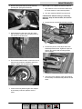
1
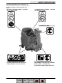
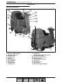
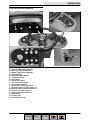
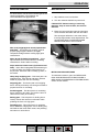
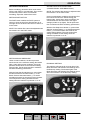
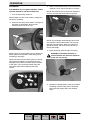
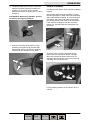
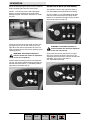
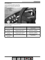
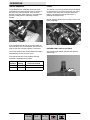
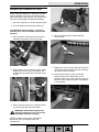
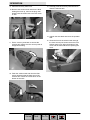
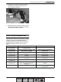
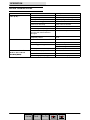
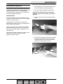
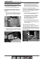
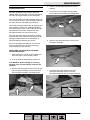
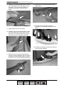
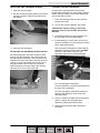
TENNANT T7
SCRUBBER DRYER
OPERATOR MANUAL
Clemas & Co. Unit 5 Ashchurch Business Centre, Alexandra Way, Tewkesbury,
Gloucestershire, GL20 8NB.
Tel: 01684 850777
Fax: 01684 850707
Email: [email protected]
Web: www.clemas.co.uk
SAFETY PRECAUTIONS
The safety labels appear on the machine in the
locations indicated. If these or any label becomes
damaged or illegible, install a new label in its
place.
BATTERY CHARGING LABEL -- LOCATED
ON THE SEAT PANEL
FLAMMABLE SPILLS LABEL -- LOCATED
ON THE SEAT PANEL
FOR SAFETY LABEL -LOCATED ON THE SEAT PANEL
FLAMMABLE MATERIALS LABEL -LOCATED UNDER THE SOLUTION FILL
PORT AND NEXT TO FOOT PEDALS
ELECTRICAL COMPONENTS, USE
GROUNDING STRAP BEFORE OPENING
PANEL LABEL -- LOCATED ON
ELECTRICAL PANEL UNDER THE SEAT
3
T7 331051 (11--04)
Home
Find... Go To..
OPERATION
OPERATION
MACHINE COMPONENTS
D
B
I
P
C
Q
E
R
S
J
A
K
G
N
H
O
M
L
F
A.
B.
C.
D.
E.
F.
G.
H.
I.
J.
Recovery tank drain hose
Recovery tank cover
Recovery tank
Operator seat
Batteries
Rear squeegee
Side squeegee
Scrub head
Steering wheel
Solution tank
K. Tool Box or
optional FaST--PAK compartment
L. Solution tank fill cap
M. Solution tank drain hose
N. Squeegee hose
O. Front solution tank cover
P. Hour meter
Q. Circuit breakers
R. 100 A Fuse
S. Battery charging connector
4
T7 331051 (11--04)
Home
Find... Go To..
OPERATION
CONTROLS AND INSTRUMENTS
F
H
E
G
A
D
C
B
R
J
L
N
P
Q
I
K
A.
B.
C.
D.
E.
F.
G.
H.
I.
J.
K.
L.
M.
N.
O.
P.
Q.
R.
M
0
Solution tank empty indicator
Recovery tank full indicator
Battery charge level indicators
Fault indicator
Emergency Stop Button
Directional switch
Horn button
On/Off key switch
One Step scrub button
FaST button (option)
Vacuum fan / squeegee button
Brush Pressure increase button (+)
Brush Pressure decrease button (--)
Solution increase button (+)
Solution decrease button (--)
Brake pedal
Propel pedal
Control panel cover
5
T7 331051 (11--04)
Home
Find... Go To..
OPERATION
FOAM SCRUBBING SYSTEM (FAST MODE)
HOW THE MACHINE WORKS
The machine solution tank, scrub brushes,
squeegee, vacuum fan, and recovery tank work
together to effectively clean dirty floors.
Water and detergent from the solution tank flow to
the floor through a solution valve. The brushes
use the detergent and water solution to scrub the
floor clean. As the machine propels forward, the
squeegee wipes the dirty solution from the floor.
The suction created by the vacuum fan then
draws the dirty solution from the squeegee into
the recovery tank.
Unlike conventional scrubbing, the optional FaST
(Foam Scrubbing Technology) system operates by
injecting the FaST--PAK concentrate agent into
the system with a small amount of water and air.
This mixture creates a large volume of expanded
wet foam.
The expanded foam mixture is then dispersed
onto the floor while the machine is scrubbing.
When the squeegee picks up the mixture, the
patented foaming agent has collapsed and is
recovered into the recovery tank.
The steering wheel controls the path of the
machine travel. The directional switch controls the
forward or reverse direction of the machine. The
propel pedal controls the speed of the machine.
The brake pedal slows and stops the machine.
The buttons on the control panel control the
machine scrubbing functions. The One Step
Scrub button turns the preset scrub functions on
and off. The FaST button controls use of the
Foam scrubbing system. The vacuum fan /
squeegee button turns the vacuum fan on/off and
raises and lowers the squeegee. The brush
pressure buttons control the scrub brush
pressure, and the solution buttons control the
solution flow.
There are two different types of scrub heads
available, cylinderical and disk. Both scrub heads
are available in two different widths. The Disk
scrub head is available in 650 mm (26 in) wide and
800 mm (32 in) wide. The Cylinderical scrub head
is available in 700 mm (28 in) wide and 800 mm
(32 in) wide.
NOTE: The amount and type of soilage play an
important role in determining the type of brushes
or pads to use. For specific recommendations,
see the BRUSH INFORMATION section of this
manual or contact a Tennant representative.
The FaST system can be used with all double
scrubbing and heavy duty scrubbing applications.
Using the FaST system improves safety and can
increase productivity by 30% by reducing your
dump/fill cycle. It will also reduce chemical usage
and storage space. One FaST--PAK of
concentrated agent can scrub up to 90,000 m2 (1
million square feet).
NOTE: Do not use the FaST system with
conventional cleaning detergents in the solution
tank. Drain, rinse and refill the solution tank with
clear cool water before operating the FaST
system. Conventional cleaning detergents may
cause failure to the FaST system.
6
T7 331051 (9--06)
Home
Find... Go To..
OPERATION
BRUSH INFORMATION
MACHINE SETUP
For best results, use the correct brush type for the
cleaning application. The following are
recommended brush applications.
ATTACHING SQUEEGEE ASSEMBLY
1. Stop machine on a level surface.
2. Turn the machine ON/OFF key switch off.
FOR SAFETY: Before leaving or servicing
machine, stop on level surface, and turn off
machine.
3. Place the rear squeegee under the squeegee
mount bracket and fasten with the two knobs.
The squeegee deflection is set at the factory.
If the squeegee blade needs adjustments, see
ADJUSTING REAR SQUEEGEE BLADE
DEFLECTION section of this manual.
Non-scuff polypropylene brush (Cylinderical
and Disk) -- This brush uses a softer, general
purpose polypropylene bristle to lift lightly
compacted soilage without scuffing high-gloss
coated floors.
Nylon brush (Cylinderical and Disk) -- Softer
nylon bristles are recommended for scrubbing
coated floors. Cleans without scuffing
Super abrasive bristle brush (Cylinderical and
Disk) -- Nylon fiber impregnated with abrasive grit
to remove stains and soilage. Strong action on
any surface. Performs well on buildup, grease, or
tire marks.
Heavy duty stripping pad -- This black pad is for
stripping floors. Cuts through old heavy finishes
easier to prepare the floor for recoating.
INSTALLING BRUSHES/PADS
To install the brushes or pad, see REPLACING
DISK SCRUB BRUSHES OR PAD DRIVER or
REPLACING CYLINDERICAL SCRUB BRUSHES
section of this manual.
Stripping pad -- This brown pad is for stripping
floors. Quickly and easily cuts through old finish to
prepare the floor for recoating.
Scrubbing pad -- This blue pad is for scrubbing
floors. Removes dirt, spills, and scuffs. Leaves a
clean surface ready for recoating.
Buffing pad -- This red pad is for buffing floors.
Quickly cleans and removes scuff marks while
polishing the floor to a high gloss.
Polishing pad -- This white pad is for polishing
floors. Maintains a high gloss. Use for buffing very
soft finishes and lower traffic areas, and polishing
soft waxes on wood floors.
7
T7 331051 (9--06)
Home
Find... Go To..
OPERATION
FILLING THE SOLUTION TANK
The machine is equipped with a fill port at the rear
of the machine.
MACHINE OPERATION
PRE--OPERATION CHECKLIST
- Check the battery fluid and charge level.
- Check the tank cover seals for damage and
wear.
- Clean the vacuum fan inlet filter.
- Check the condition of the scrubbing brushes.
Remove any string, banding, plastic wrap, or
other debris wrapped around them.
- Cylinderical brushes: Check that the debris
tray is empty and clean.
WARNING: Flammable materials can
cause an explosion or fire. Do not use
flammable materials in tank(s).
FOR CONVENTIONAL SCRUBBING: Open the
solution tank fill port and partially fill it with water
(not to exceed 60°C / 140°F). Pour the required
amount of detergent into the solution tank
according to mixing instructions on the bottle.
Then continue filling the solution tank with warm
water until the water level is just below the fill port.
FOR SAFETY: When using machine, follow
mixing and handling instructions on chemical
containers.
FOR FOAM SCRUBBING (FaST MODE) : FILL
THE TANK WITH ONLY CLEAN COOL WATER
(less than 21°C / 70°F). DO NOT use hot water or
add any conventional floor cleaning detergents or
FaST system failure may result.
NOTE: When filling the solution tank with a
bucket, make sure that the bucket is clean. Do not
use the same bucket for filling and draining the
machine.
ATTENTION: For Conventional Scrubbing,
only use recommended cleaning detergents.
Machine damage due to improper detergent
usage will void the manufacturer’s warranty.
- Check the squeegees for damage, wear and
for deflection adjustment.
- Check the vacuum hose for debris or
blockage.
- Drain and clean the recovery tank.
- Check the brakes and steering for proper
operation.
- Check the service records to determine
maintenance requirements.
- FaST Scrubbing: Check the FaST--PAK
(option) concentrate agent level. Replace
carton as needed. See the INSTALLING THE
FaST--PAK AGENT section of the manual.
- FaST Scrubbing: Ensure that all conventional
cleaning agents are drained and rinsed from
the solution tank.
- FaST Scrubbing: Ensure that the solution tank
is filled with clear cool water only.
BEFORE OPERATING
Pick up oversized debris before scrubbing. Pick
up pieces of wire, string, twine, etc., that could
become wrapped around the scrub brush.
Plan the scrubbing in advance. Try to arrange
long runs with minimum stopping and starting. Do
an entire floor or section at one time.
Pre--sweep the area to prevent streaking.
8
T7 331051 (9--06)
Home
Find... Go To..
OPERATION
SETTING SCRUB MODES
Before scrubbing, determine which scrub mode
will be used (FaST or conventional). Then set the
scrub brush pressure and if conventional
scrubbing, adjust the solution flow levels.
SETTING FaST BUTTON
The FaST button enables the FaST system to
come on when the One Step Scrub button is on.
The light next to the button will come on when it is
in this mode.
NOTE: The solution flow cannot be adjusted when
the machine is in the FaST mode.
SETTING SOLUTION FLOW LEVEL
(CONVENTIONAL SCRUBBING ONLY)
NOTE: The solution flow cannot be adjusted when
the machine is in the FaST mode.
Under normal soilage conditions the solution flow
level should be set to the lowest setting (the
bottom light). Under heavy grime conditions, the
solution flow level should be set to the higher
settings (middle or top lights). Travel speed and
floor conditions will affect scrubbing performance.
With the One Step Scrub button on, press either
Solution increase button (+) or Solution decrease
button (--) to set the solution flow level for the
surface being cleaned. The new solution flow
setting will default to this setting when the
machine is powered on or off.
SETTING BRUSH PRESSURE
Under normal conditions, the brush pressure
should be set to the minimum setting (the bottom
light). Under heavy grime conditions, the brush
pressure should be set to the maximum setting
(the top light). Travel speed and floor conditions
will affect scrubbing performance.
With the One Step Scrub button on, press either
the Brush Pressure increase button (+) or the
Brush Pressure decrease button (--) to set the
scrubbing pressure for the surface being cleaned.
The new pressure setting will default to this
setting when the machine is powered on or off.
ECONOMY SETTING
The machine will operate for a longer time if the
Brush Pressure and Solution Flow settings are in
the Economy setting. The bottom lights of the
Brush Pressure and Solution Flow settings are on
when the machine is in the Economy setting.
9
T7 331051 (11--04)
Home
Find... Go To..
OPERATION
SCRUBBING
FOR SAFETY: Do not operate machine, unless
operator manual is read and understood.
1. Turn the On/Off key switch on.
3. Place the directional switch in the direction the
machine is to be moved (forward or reverse).
NOTE: The machine can scrub in both forward or
reverse. The horn will sound when in reverse.
NOTE: Make sure the scrub modes / settings are
set before scrubbing.
2. Press the One Step Scrub button. The light on
the button is illuminated. All the preset
scrubbing functions will turn on.
NOTE: The squeegee automatically raises when
the machine is driven backwards. This prevents
damaging the squeegee. When the machine is
placed in reverse, the vacuum fan will shut off
after a short delay.
4. Press the propel pedal to begin scrubbing.
NOTE: Open the control panel cover to adjust the
Brush Pressure and Solution Flow Setting while
scrubbing if necessary.
WARNING: Flammable materials or
reactive metals can cause an explosion
or fire. Do not pick up.
NOTE: DO NOT turn the FaST system on during
conventional scrubbing. Conventional cleaning
detergents may cause the FaST injection system
to fail. Drain, rinse, and refill solution tank with
cool clean water before operating the FaST
system.
5. Release the propel pedal to stop the machine.
Scrubbing functions stop and the automatic
park brake will engage when the machine
stops.
10
T7 331051 (11--04)
Home
Find... Go To..
OPERATION
6. The Brake pedal can be used to control the
machine if quicker stopping is needed or if
operating on an incline. Do not operate
machine on inclines exceeding 7% (4_) when
scrubbing.
FOR SAFETY: When using machine, go slow
on inclines and slippery surfaces.
DOUBLE SCRUBBING
For heavily soiled areas, use the double scrubbing
method.
Disk brushes: Before double scrubbing, remove
the side squeegees to keep them from channeling
water while double scrubbing. To remove the side
squeegees, lower the scrub head, then pull the
pins on the front and rear ends of the squeegees.
If the machine is equipped with the accessory
basket, you may hang the side squeegees from
the hooks.
7. Press the One Step Scrub button to stop
scrubbing. The light next to the One Step
Scrub button will turn off and the scrubbing
functions will turn off after a short delay.
To double scrub, press the One Step Scrub
button, then the vacuum fan button. The light
above the vacuum fan button will turn off, the
squeegee will raise and the vacuum fan will stop
operating. Then scrub the area.
Let the cleaning solution set on the floor for 3--5
minutes.
11
T7 331051 (9--06)
Home
Find... Go To..
OPERATION
Place the side squeegees back on to the machine
before scrubbing the floor the second time.
NOTE: It is easier to put the side squeegees
back on to the machine with the scrub head
partially lowered. This allows clearance to install
the pins.
WATER PICKUP MODE (NO SCRUBBING)
The machine can be used to pick up water or
non--flammable liquid spills without scrubbing.
To pick up water or non--flammable liquid spills,
check to make sure that the One Step Scrub
button is not activated. The light next to the One
Step Scrub button must be off.
Press the vacuum fan button again to lower the
squeegee and to turn on the vacuum fan. The
light above the vacuum fan button will come on.
Then scrub the floor a second time picking up the
cleaning solution.
WARNING: Flammable materials or
reactive metals can cause an explosion
or fire. Do not pick up.
NOTE: When scrubbing the area a second time,
you can turn off the solution flow by pressing the
Solution decrease button (--) repeatedly until all
lights above the button are off.
WARNING: Flammable materials or
reactive metals can cause an explosion
or fire. Do not pick up.
Then press the vacuum fan button. The light
above the vacuum fan button will turn on, the
squeegee will lower and the vacuum fan will start
operating. Then pick up the water or
non--flammable liquid spill.
12
T7 331051 (11--04)
Home
Find... Go To..
OPERATION
WHILE OPERATING THE MACHINE
EMERGENCY STOP BUTTON
Drive as straight a path as possible. Avoid
bumping into posts or scraping the sides of the
machine. Overlap the scrub paths by several
centimeters (a few inches).
The Emergency Stop Button halts all power to the
machine in case of an emergency. Press the
button to halt the machine power. To restart the
machine, turn the Emergency Stop Button to the
right. Then turn the on/off switch to the off position
and then to the on position.
Avoid turning the steering wheel too sharply when
the machine is in motion. The machine is very
responsive to the movement of the steering wheel.
Avoid sudden turns, except in emergencies.
When scrubbing dead end aisles, start at the
closed end of the aisle and scrub out towards the
opening.
NOTE: This button should not be used for normal
stopping as premature wear to the parking brake
may occur.
Adjust the machine speed, brush pressure, and
solution flow as required when scrubbing. Use the
minimal brush pressure and solution flow settings
as possible. Use the FaST system for the best
results.
Keep the machine moving to prevent damaging
floor finishes.
If poor scrubbing performance is observed, stop
scrubbing and refer to MACHINE
TROUBLESHOOTING.
Conventional Scrubbing: Pour a recommended
foam control solution into the recovery tank if
excessive foam appears.
Change or rotate pads as necessary.
HOUR METER
The hour meter records the number of hours the
machine has been powered on. This information is
useful for servicing the machine. It is located
under the seat.
Observe the battery discharge indicator to ensure
there is adaquate charge for machine operation.
Observe the solution tank indicator to ensure the
solution tank is not empty. Always empty recovery
tank before refilling the solution tank.
Observe the recovery tank indicator to ensure the
recovery is not full.
Remove the key when leaving the machine
unattended.
Perform the Daily Maintenance Procedures after
scrubbing (see MACHINE MAINTENANCE).
13
T7 331051 (11--04)
Home
Find... Go To..
OPERATION
SOLUTION TANK EMPTY INDICATOR
BATTERY DISCHARGE INDICATOR
The solution tank empty indicator comes on when
the solution tank is empty. When this happens, the
scrub functions are disabled. If necessary, press
the ONE STEP Scrub button for an additional
minute of operation to pick up standing water or
solution.
The battery discharge indicator shows the charge
level of the batteries.
When the batteries are fully charged, all five lights
are lit. As the batteries discharge, the lights go out
until only the left light is blinking.
RECOVERY TANK FULL INDICATOR
The recovery tank full indicator comes on when
the recovery tank is full. When this happens, the
scrub functions are disabled. If necessary, press
the ONE STEP Scrub button for an additional
minute of operation to pick up standing water or
solution.
When the left light blinks, the scrubbing functions
will shut off to alert the operator of the battery
condition. The machine will still propel when the
light is blinking. Recharge the batteries when the
light blinks. If necessary, press the ONE STEP
Scrub button for an additional minute of operation
to pick up standing water or solution.
NOTE: Do not charge batteries more often than
necessary. Excessive charging could reduce the
life of the batteries. It is best to charge the
batteries only when the left light indicates that the
battery needs charging. See BATTERIES in the
MAINTENANCE section.
NOTE: The blinking left battery discharge light will
not reset from blinking until the batteries are fully
charged.
14
T7 331051 (11--04)
Home
Find... Go To..
OPERATION
FAULT INDICATOR
The fault indicator light (shown in upper right)
comes on when there a fault is detected in the
propelling motor, vacuum fan motor, or brush
motors.
Refer to the table below to determine the cause
for the fault or failure.
Indicator(s)
Fault Light blinks
Cause(s)
Propel motor is overloaded
Fault Light and bottom
Brush Pressure Light
both blink
Fault Light and top
Brush Pressure Light
both blink
Fault Light and
Vacuum Fan Light
both blink
Right Brush Motor is overloaded
(possibly from string or banding
wrapped around motor)
Left Brush Motor is overloaded
(possibly from string or banding
wrapped around motor)
Vacuum Fan Motor is overloaded
Remedy
Contact Tennant service
representative
Remove string / banding from Right
brush motor or Contact
Tennant service representative
Remove string / banding from Left
brush motor or Contact
Tennant service representative
Contact Tennant service
representative
15
T7 331051 (11--04)
Home
Find... Go To..
OPERATION
CIRCUIT BREAKERS
FUSES
Circuit breakers are resettable electrical circuit
protection devices that stop the flow of current in
the event of a circuit overload. Once a circuit
breaker is tripped, allow breaker to cool and then
press the reset button to manually reset the
breaker.
The fuse is a one-time protection device designed
to stop the flow of current in the event of a circuit
overload. The 100 A fuse is located inside the
battery compartment near the hourmeter. It
protects the propel circuit.
NOTE: Always replace the fuse with a fuse of the
same amperage.
If the overload that caused the circuit breaker to
trip is still there, the circuit breaker will continue to
stop current flow until the problem is corrected.
HAZARD LIGHT SWITCH (OPTION)
The circuit breakers are located inside the battery
compartment next to the hour meter.
The Hazard Light Switch operates the optional
hazard light.
The chart shows the circuit breakers and the
electrical components they protect.
Circuit
Breaker
Rating
Circuit Protected
CB1
5A
Instrument Panel -- power
CB2
15 A
Accessories
16
T7 331051 (9--06)
Home
Find... Go To..
OPERATION
DRAINING AND CLEANING THE TANKS
When cleaning is finished, or when the recovery
tank full indicator comes on, the recovery tank
should be drained and cleaned. The solution tank
then can be filled again for additional cleaning.
1. Drive the machine to a solution disposal drain.
2. Turn the machine ON/OFF key switch off.
FOR SAFETY: Before leaving or servicing
machine, stop on level surface, and turn off
machine.
3. Tilt the operator seat forward and hook the
seat latch into place to hold up the seat.
4. Remove the recovery tank drain hose. While
holding the hose up, remove the plug, then
slowly lower the drain hose to the floor drain
or sink.
6. Rinse the float sensor located inside the
recovery tank.
7. Replace the recovery tank drain hose cap and
mount the drain hose back onto the mounting
clip after the tank is drained.
8. Remove and clean the vacuum fan filter.
Clean the filter with a damp cloth or low
pressure water hose if dirty. Allow the vacuum
fan filter to dry completely before reinstalling it
in the machine.
5. Lift the recovery tank cover. Flush the inside
of the recovery tank with clean water.
WARNING: Flammable materials can
cause an explosion or fire. Do not use
flammable materials in tank(s).
NOTE: DO NOT use steam to clean tanks.
Excessive heat can damage tanks and
components.
17
T7 331051 (11--04)
Home
Find... Go To..
OPERATION
9. Close the recovery tank cover.
10.Remove the solution tank drain hose. While
holding the hose up, remove the plug, then
slowly lower the drain hose to the floor drain
or sink.
13. Carefully push the recovery tank forward to
close the solution tank.
14. Unhook the seat latch and lower the operator
seat.
11. Tilt the recovery tank back to access the
solution tank. Make sure the recovery tank is
empty before tilting.
15. Clean the front of the solution tank through
the front access port located under the front
solution tank cover. Wipe the bottom of the
cover and the tank seal before replacing the
cover.
12. Flush the solution tank and rinse the float
sensor located inside the back part of the
solution tank. Rinse the screen filter on the
bottom of the tank.
18
T7 331051 (9--06)
Home
Find... Go To..
OPERATION
16. Cylinderical scrub head: Remove and clean
the debris tray. Place the tray back in the
scrub head when finished.
17. Replace the solution tank drain hose cap and
mount the drain hose back onto the mounting
clip after after the tank is drained.
PROPEL SYSTEM TROUBLESHOOTING
The audio alarm (horn) will sound and/or warning
lights will come on when a propelling system fault
or failure is detected. The machine will stop
propelling when this happens. Refer to the table
below to determine the cause for the fault or
failure.
Indicator(s)
Horn repeatedly
beeps 2 times
Horn repeatedly
beeps 4 times
Horn repeatedly
beeps 5 times
Horn repeatedly
beeps 6 times
Horn repeatedly
beeps 7 times
Horn repeatedly
beeps 8 times
Horn repeatedly
beeps 9 times
Fault Light blinks
Cause(s)
Propel pedal depressed without
operator in seat
ON/OFF key switch is turned on while
propel pedal is engaged
Failure in the Throttle system has
occurred
Failure in the Brake system has
occurred
Failure in the Parking Brake system
has occurred
Emergency Stop Button is engaged
Remedy
Sit in seat when operating machine
ON/OFF key switch is turned on while
battery charger is plugged into
machine
Propel motor is overloaded
Unplug battery charger before starting
machine
Release the propel pedal before
turning key on
Contact Tennant service
representative
Contact Tennant service
representative
Contact Tennant service
representative
Reset Emergency Stop Button
Contact Tennant service
representative
19
T7 331051 (9--06)
Home
Find... Go To..
OPERATION
MACHINE TROUBLESHOOTING
Problem
Trailing
g water--poor
p
or no
water
t pickup
i k
Vacuum fan will not turn on
Cause
Remedy
Vacuum fan turned off
Turn vacuum fan on
Worn squeegee blades
Rotate or replace squeegee blades
Squeegee out of adjustment
Adjust squeegee
Vacuum hose clogged
Flush vacuum hoses
Vacuum fan filter dirty
Clean vacuum fan filter
Vacuum fan cover seals worn
Replace seals
Debris caught on squeegee
Remove debris
Vacuum hose to squeegee or
recovery tank disconnected or
damaged
Reconnect or replace vacuum hose
Recovery tank cover not
completely closed
Check for obstructions and close
cover
Vacuum fan switch turned off
Turn vacuum switch on
Recovery tank full
Foam filling
g recoveryy tank
Drain recovery tank
Empty recovery tank
Use less detergent
Recovery tank sensor dirty or stuck Clean or replace sensor
Little or no solution flow to
th floor
the
fl
(Conventional
(C
ti
l
Scrubbing Mode)
Solution tank empty
Fill solution tank
Solution flow turned off
Turn solution flow on
Solution supply lines plugged
Flush solution supply lines
20
T7 331051 (11--04)
Home
Find... Go To..
OPERATION
Problem
Poor scrubbing
g performance
p
FaST System does not
operate
t
Cause
Remedy
One Step Scrub button not on
Turn One Step Scrub button on
Improper detergent or brushes
used
Contact Tennant service
representative
Recovery tank full
Empty recovery tank
Solution tank empty
Fill solution tank
Debris caught on scrub brushes or
pads
Remove debris
Worn scrub brush
Replace scrub brush
Broken or loose brush drive belt
(Cylinderical models)
Replace or tighten belt
Brush pressure set too light
Increase brush pressure
Low battery charge
Charge batteries until the charger
automatically turns off
FaST switch is turned off
Turn on the FaST swiitch
Accessory circuit breaker tripped
Reset circuit breaker
Clogged FaST--PAK supply hose
and/or connector
Soak connector and hose in warm
water and clean
FaST--PAK carton is empty or not
connected
Replace FaST--PAK carton and/or
connect supply hose
FaST system is not primed
To prime, operate the FaST solution system for a few minutes
Clogged filter screen
Drain solution tank, remove and
clean filter screen
Faulty solution pump
Replace solution pump
21
T7 331051 (9--06)
Home
Find... Go To..
MAINTENANCE
MAINTENANCE
9
3
8
7
3
1
3
10
5
6
10
3
4
11
2
1
14
12
13
22
T7 331051 (9--06)
Home
Find... Go To..
MAINTENANCE
MAINTENANCE CHART
Interval
Dailyy
Key
Description
1
Side and rear squeegees
q
g
2
8
Scrub brushes / pads
Recovery tank
9
7
Vacuum fan filter
FaST--PAK supply hose
and connector (option)
Debris tray
(Cylinderical brushes)
Battery cells
(Lead acid batteries)
Disk scrub head floor skirt
Cylinderical brushes
12
4
50 Hours
11
13
3
100 Hours
14
200 Hours
4
500 Hours
9
5
6
10
Vacuum Fan and tank
seals
Cylinderical brush drive
belts
Battery terminals and
cables
Vacuum fan motor(s)
Scrub brush motors
Propelling motor
Tires
No. of
Lubricant/ Service
Fluid
Points
Procedure
Check for damage and wear
-3
Check deflection and leveling
-6
Check for damage, wear, debris
-2
Clean tank, screen filter, and float
-1
sensor
Clean
-1
Clean and connect hose to stor-1
ing plug when not in use
Clean
-1
Check electrolyte level
DW
3
Check for damage and wear
Check taper and rotate front to
rear
Check for damage and wear
---
2
2
--
3
Check tension
--
2
Check and clean
--
12
Check motor brushes
Check motor brushes
Check motor brushes
Check for damage and wear
-----
1
2
1
3
LUBRICANT/FLUID
DW . . . . Distilled water
23
T7 331051 (9--06)
Home
Find... Go To..
MAINTENANCE
BATTERIES
LEAD ACID BATTERIES
The batteries are designed to hold their power for
long periods of time. The lifetime of the batteries
is limited to number of charges the batteries
receive. To get the most life from the batteries,
recharge them immediately when the battery
discharge indicator begins to blink.
Check the electrolyte level in each battery cell
before and after charging, and after every 50
hours of operation. Never add acid to the
batteries. Add distilled water only. Always keep
the battery caps on, except when adding water or
taking hydrometer readings.
FOR SAFETY: When servicing machine, wear
protective gloves when handling batteries or
battery cables. Avoid contact with battery
acid.
Using a hydrometer, measure the specific gravity
to determine the charge level and condition of the
batteries. If one or more of the battery cells test
lower than the other battery cells (0.050 or more),
the cell is damaged, shorted, or is near failure.
Completely recharge the batteries and then retest.
After every 200 hours of use check for loose
battery connections and clean the surface of the
batteries, including terminals and cable clamps,
using a strong solution of baking soda and water.
Brush the solution sparingly over the battery tops.
Do not allow any baking soda solution to enter the
batteries. Use a wire brush to clean the terminal
posts and the cable connectors. Wipe off all
cleaning solution residue. After cleaning, apply a
coating of clear battery post protectant to the
terminals and the cable connectors. Keep the tops
of the batteries clean and dry.
Objects made of metal can potentially short circuit
the batteries. Keep all metallic objects off the
batteries. Replace any worn or damaged wires.
Replace any defective batteries. To dispose of
batteries, contact a battery dealer or your Tennant
Service representative.
04380
GEL BATTERIES
The Gel batteries are maintenance free and do
not need to have the electrolyte level checked.
24
T7 331051 (9--06)
Home
Find... Go To..
MAINTENANCE
NOTE: Do not take readings immediately after
adding distilled water. If the water and acid are not
thoroughly mixed, the readings may not be
accurate. Check the hydrometer readings against
the following chart to determine the remaining
battery charge level:
SPECIFIC GRAVITY
at 27_ C (80_F)
BATTERY
CHARGE
1.265
100% Charged
1.223
75% Charged
1.185
50% Charged
1.148
25% Charged
1.110
Discharged
NOTE: If the readings are taken when the battery
electrolyte is any temperature other than 27_ C
(80_ F), the reading must be temperature
corrected. Add or subtract to the specific gravity
reading 0.004, 4 points, for each 6_ C(10_ F)
above or below 27_C(80_ F).
CHARGING THE BATTERIES WITH
OFF--BOARD CHARGER
1. Drive the machine to a flat, dry surface.
NOTE: Make sure the area is well ventilated.
4. Lead acid batteries: Check the water level in
all battery cells. If the level is low, add just
enough distilled water to cover the plates. DO
NOT OVERFILL. The batteries can overflow
during charging due to expansion.
NOTE: Make sure the battery caps are in place
while charging.
FOR SAFETY: When servicing machine, wear
protective gloves when handling batteries or
battery cables. Avoid contact with battery
acid.
5. Plug the charger connector into the machine
battery charging connector.
2. Turn the machine ON/OFF key switch off.
FOR SAFETY: Before leaving or servicing
machine, stop on level surface, and turn off
machine.
WARNING: Batteries emit hydrogen gas.
Explosion or fire can result. Keep
sparks and open flame away. Keep
covers open when charging.
3. Tilt the operator seat forward and hook the
seat latch into place to hold up the seat
25
T7 331051 (9--06)
Home
Find... Go To..
MAINTENANCE
6. Plug the battery charger into the wall outlet.
NOTE: If the red “ABNORMAL CYCLE” lamp
lights when the TENNANT charger is plugged into
a wall outlet, the charger cannot charge the
battery and there is something wrong with the
battery.
ELECTRIC MOTORS
The carbon brushes on the vacuum fan motor, the
propelling motor, and the scrub brush motors
should be inspected after the initial 500 hours of
machine operation and then every 100 hours after
the initial 500 hours.
BELTS (Cylinderical Models)
07224
7. The TENNANT charger will start
automatically. When the batteries are fully
charged, the TENNANT charger will
automatically turn off.
The two brush drive belts are located on the
cylindrical brush scrub head. The belts drive the
cylindrical brushes. Proper belt tension is a 6 mm
(0.25 in) deflection from a force of 2.3 to 2.5 kg
(5.0 to 5.4 lb) at the belt midpoint.
Check and adjust the belt tension every 100 hours
of operation.
NOTE: Do not disconnect he charger’s DC cord
from the machine’s battery charging connector
when the charger is operating. Arcing may result.
If the charger must be interrupted during charging,
disconnect the AC power supply cord first.
8. After the charger has turned off, unplug the
charger from the machine battery charging
connector.
9. Lead acid batteries: Check the electrolyte
level in each battery cell after charging. If
needed, add distilled water to raise the
electrolyte level to about 12 mm (0.4 in) below
the bottom of the sight tubes.
10. Unhook the seat latch and lower the operator
seat.
26
T7 331051 (07--07)
Home
Find... Go To..
MAINTENANCE
REPLACING DISK BRUSHES OR PAD DRIVER
SCRUB BRUSHES AND PADS
The machine can be equipped with either disk or
cylindrical scrub brushes, or cleaning pads. Check
scrub brushes daily for wire or string tangled
around the brush or brush drive hub. Also check
for brushes damage and wear.
DISK BRUSHES
The scrub brushes should be replaced if a large
number of bristles are missing or if bristle length is
less than 10 mm (0.38 in).
1. Stop machine on a level surface. Make sure
the scrub head is in the raised position.
2. Turn the machine ON/OFF key switch off.
FOR SAFETY: Before leaving or servicing
machine, stop on level surface, and turn off
machine.
3. Pull the pin from the side squeegee retainer
pivot.
Cleaning pads must be placed on pad drives
before they are ready to use. The cleaning pad is
held in place by a pad holder.
Cleaning pads need to be cleaned immediately
after use with soap and water. Do not wash the
pads with a pressure washer. Hang pads, or lie
pads flat to dry.
NOTE: Always replace brushes and pads in sets.
Otherwise one brush or pad will be more
aggressive than the other.
4. Open the side squeegee retainer pivot toward
the front of the machine, then pull the side
squeegee toward the rear of the machine to
access the scrub brushes or pads.
27
T7 331051 (9--06)
Home
Find... Go To..
MAINTENANCE
5. Pull the scrub brush/pad driver downward to
remove it from the drive hub.
REPLACING DISK PADS
1. Remove the pad driver from the machine.
2. Squeeze the spring clip together to remove
the center disk.
6. Place the new scrub brush/pad driver onto the
drive hub. Ensure that it is securely mounted
onto the brush drive hub.
3. Flip or replace the scrub pad, center the scrub
pad on the pad driver. Then reinstall the
center disk to secure the pad in place on the
pad driver.
7. Close the side squeegee and the retainer
pivot, then insert the pin.
NOTE: Be sure the pin is inserted completely
through the bottom.
4. Reinsert the pad driver into the machine.
28
T7 331051 (9--06)
Home
Find... Go To..
MAINTENANCE
CYLINDERICAL BRUSHES
Check the brush taper and rotate the brushes
from front-to-rear every 50 hours of machine
operation for maximum brush life and best
scrubbing performance.
4. Remove idler plate from the scrub head by
pressing the spring tab downward.
The cylindrical brushes should be replaced if large
amounts of bristles are missing, or if the
remaining bristle length is less than 15 mm
(0.62 in).
NOTE: Replace worn brushes in pairs. Scrubbing
with brushes of unequal bristle length will result in
diminished scrubbing performance.
REPLACING OR ROTATING CYLINDERICAL
BRUSHES
1. Stop machine on a level surface. Make sure
the scrub head is in the raised position.
2. Turn the machine ON/OFF key switch off.
5. Pull the old brush out of the scrub head.
6. Attach the idler plate to the new or rotated
brush on the end that has the double row of
bristles. Install the brush.
FOR SAFETY: Before leaving or servicing
machine, stop on level surface, and turn off
machine.
3. Remove the cotter pin that holds the side
squeegee in place. Swing the squeegee away
from the scrub head.
7. Push down on the door to catch the door in
the scrub head, then pull up on the door to
latch it into the spring.
8. Repeat for the other brush on the other side
of the scrub head
NOTE: Each side of the scrub head is stamped
with a letter. The idler door of that side of the
scrub head is stamped with the same letter. Make
sure the letter on the door matches the letter on
the scrub head when replacing the doors.
29
T7 331051 (9--06)
Home
Find... Go To..
MAINTENANCE
CHECKING CYLINDERICAL BRUSH PATTERN
1. Apply chalk, or a similar marking material, to a
smooth and level section of the floor.
8. If the width of the brushes is not the same,
see ADJUSTING CYLINDERICAL BRUSH
WIDTH section of this manual.
NOTE: If chalk or other material is not available,
allow the brush to spin on the floor for two
minutes. A polish mark will remain on the floor.
2. Raise the scrub head, then position the
brushes over the chalked area.
3. Block the front or rear wheels to prevent the
machine from moving.
4. Lower the scrub head in the chalked area.
Slowly press down on the directional pedal
until the brushes begin to sweep. Allow the
machine to sweep in the same place for 15 to
20 seconds.
5. Raise the scrub head and drive the machine
away from the chalked area.
FOR SAFETY: Before leaving or servicing
machine, stop on level surface, and turn off
machine.
6. Observe the brush patterns. If the brush
pattern is the same width across the entire
length of each brush and both brushes are the
same width, no adjustment is necessary.
10653
ADJUSTING CYLINDERICAL BRUSH TAPER
FOR SAFETY: Before leaving or servicing
machine, stop on level surface, and turn off
machine.
1. Stop machine on a level surface. Make sure
the scrub head is in the raised position.
2. Turn the machine ON/OFF key switch off.
FOR SAFETY: Before leaving or servicing
machine, stop on level surface, and turn off
machine.
3. Remove the cotter pin that holds the side
squeegee in place. Swing the squeegee away
from the scrub head.
10355
7. If the brush patterns are tapered, see
ADJUSTING CYLINDERICAL BRUSH
TAPER section of this manual.
10652
30
T7 331051 (07--07)
Home
Find... Go To..
MAINTENANCE
4. Remove idler plate from the scrub head by
pressing the spring tab downward.
ADJUSTING CYLINDERICAL BRUSH WIDTH
1. Stop machine on a level surface. Make sure
the scrub head is in the lowered position.
2. Turn the machine ON/OFF key switch off.
FOR SAFETY: Before leaving or servicing
machine, stop on level surface, and turn off
machine.
3. Loosen the two scrub head mounting screws.
5. While holding the flat end of the idler shaft
with a wrench, loosen the mounting screw on
the outside of the idler door.
4. Loosen the jam nut, then adjust the brush
width adjustment screw. Tighten the jam nut
and the two scrub head mounting screws
when finished.
6. Turn the idler shaft to raise or lower the end of
the brush as needed to straighten the brush
pattern. Tighten the mounting screw.
5. Check the brush patterns again and readjust
as necessary until both brush patterns are the
same.
7. Check the brush patterns again and readjust
as necessary until both patterns are the
same.
31
T7 331051 (9--06)
Home
Find... Go To..
MAINTENANCE
REPLACING THE FaST--PAK (FaST Model)
1. Stop machine on a level surface.
2. Turn off the machine ON/OFF key switch.
FOR SAFETY: Before leaving or servicing
machine, stop on level surface, and turn off
machine.
3. Open the FaST--PAK compartment door and
slide the empty FaST--PAK approximately half
way out from the FaST--PAK compartment
door.
5. Remove the perforated knock outs from the
new FaST--PAK carton. Do Not remove the
bag from the carton. Pull out the hose
connector located on the bottom of the bag
and remove the hose cap from the connector.
NOTE: The FaST--PAK Floor Cleaning
Concentrate is specially designed for use with the
FaST system scrubbing application. NEVER use a
substitute. Other cleaning solutions may cause
FaST system failure.
6. Insert the new FaST--PAK approximately half
way into the FaST--PAK compartment.
7. Connect the FaST--PAK hose connector to
the FaST supply hose connector, slide the
FaST--PAK the rest of the way into the
FaST--PAK compartment, and close the
FaST--PAK compartment door.
8. When replacing an empty FaST--PAK carton,
you must scrub with the FaST system for a
few minutes before the detergent will reach its
maximum foaming.
FaST SUPPLY HOSE CONNECTOR
4. Squeeze the button on the FaST supply hose
connector, then pull the empty FaST--PAK out
from the compartment.
The FaST supply hose connector is located below
the FaST--PAK holder. Soak the connector in
warm water if detergent buildup is visible. When a
FaST--PAK carton is not installed, store the supply
hose connector on the storing plug to prevent the
hose from clogging.
32
T7 331051 (9--06)
Home
Find... Go To..
MAINTENANCE
4. Pull the rear squeegee assembly from the
machine.
SQUEEGEE BLADES
The side squeegees control water spray and
channel water into the path of the rear squeegee.
The side squeegee blades are not adjustable.
5. Loosen the rear squeegee retaining band
tension latch and remove the retaining band.
The rear squeegee assembly channels water into
the vacuum fan suction. The front blade channels
the water and the rear blade wipes the floor.
Check the squeegee blades daily for damage and
wear. Rotate or replace the squeegee blades if
the leading edge is torn or worn half-way through
the thickness of the blade. Replace the side
squeegee deflectors if they become worn.
The rear squeegee can be adjusted for leveling
and deflection. The deflection and leveling of the
squeegee blades should be checked daily, or
when scrubbing a different type of floor.
The rear squeegee assembly can be removed
from the squeegee pivot to prevent damage
during transport of the machine.
6. Remove rear squeegee blade from the rear
squeegee assembly.
REPLACING (OR ROTATING) THE REAR
SQUEEGEE BLADES
1. Stop machine on a level surface. Make sure
the scrub head is in the raised position.
2. Turn the machine ON/OFF key switch off.
FOR SAFETY: Before leaving or servicing
machine, stop on level surface, and turn off
machine.
3. Remove the squeegee suction hose from the
rear squeegee assembly. Then loosen both
rear squeegee assembly mounting knobs.
7. Loosen the two outer knobs on the rear
squeegee assembly. Remove the front
squeegee blade from the squeegee assembly.
33
T7 331051 (11--04)
Home
Find... Go To..
MAINTENANCE
8. Install the new front squeegee blade or rotate
the existing blade to the new edge. Be sure
the holes in the front squeegee blade are
hooked onto the tabs on the front blade
clamp.
9. Lightly tighten the two outer knobs.
12. Tighten the rear squeegee retaining band
tension latch.
13.Reinstall the rear squeegee under the
squeegee mount bracket and tighten all four
knobs.
10. Install the new rear squeegee blade or rotate
the existing blade to the new edge. Be sure
the holes in the squeegee blade are hooked
onto the tabs on the squeegee assembly.
14. Reinstall the squeegee suction hose onto the
rear squeegee assembly.
11. Reinstall the rear squeegee retaining band
onto the squeegee assembly. Be sure each of
the flanges on the retaining band are seated
in the cut outs in the rear squeegee assembly.
34
T7 331051 (11--04)
Home
Find... Go To..
MAINTENANCE
REPLACING SIDE SQUEEGEE BLADES
1. Open the side squeegee.
2. Pull the old side squeegee blade from the side
squeegee retainer. Slide the new blade onto
the retainer.
LEVELING THE REAR SQUEEGEE
Leveling of the squeegee assures the entire
length of the squeegee is in even contact with the
surface being scrubbed. Perform this adjustment
on an even and level floor.
1. Lower the squeegee and drive the machine
forward a few feet.
2. Turn off the machine ON/OFF key switch.
FOR SAFETY: Before leaving or servicing
machine, stop on level surface, and turn off
machine.
3. Look at the deflection of the squeegee over
the full length of the squeegee blade.
4. If the deflection is not the same over the full
length of the blade, turn the squeegee leveling
bolt to make adjustments.
The squeegee leveling bolt is located directly
behind the squeegee suction hose. DO NOT
disconnect the suction hose from the
squeegee frame when leveling squeegee.
3. Close the side squeegee.
ADJUSTING THE SQUEEGEE GUIDE ROLLER
The squeegee guide rollers are located on both
ends of the rear squeegee. The rollers guide the
squeegee blade end along a wall. Loosen the nut
located at the top of the guide roller and move the
roller in or out to adjust how close the end of the
squeegee blade is to the wall. The squeegee
blade end should be further away from the wall
when the floor curves up into the wall.
Turn the squeegee leveling bolt
counter-clockwise to increase the deflection at
the ends of the squeegee.
Turn the squeegee leveling bolt clockwise to
decrease the deflection at the ends of the
squeegee blade.
5. Drive the machine forward with the squeegee
down to recheck the squeegee blade
deflection if adjustments were made.
6. Readjust the squeegee blade deflection if
necessary.
35
T7 331051 (9--06)
Home
Find... Go To..
MAINTENANCE
ADJUSTING REAR SQUEEGEE BLADE
DEFLECTION
Deflection is the amount of curl the overall
squeegee blade has when the machine moves
forward. The best deflection is when the
squeegee wipes the floor dry with a minimal
amount of deflection.
4. If the overall squeegee blade deflection needs
to be adjusted, loosen the jam nuts on the
squeegee casters and adjust the height.
1. Lower the squeegee and drive the machine
forward a few meters (feet).
2. Turn off the machine ON/OFF key switch.
FOR SAFETY: Before leaving or servicing
machine, stop on level surface, and turn off
machine.
3. Look at the amount of deflection or “curl” of
the squeegee blade. The correct amount of
deflection is 12 mm (0.50 in) for scrubbing
smooth floors and 15 mm (0.62 in) for rough
floors.
5. Drive the machine forward again to recheck
the squeegee blade deflection after
adjustments are made.
6. Readjust the squeegee blade deflection if
necessary.
12 mm
(0.50 in)
03719
36
T7 331051 (11--04)
Home
Find... Go To..
MAINTENANCE
SOLUTION TANK SEALS
SKIRTS AND SEALS
DISK SCRUB HEAD FLOOR SKIRT
There are two solution tank seals. Check the seal
for damage and wear after every 100 hours of
operation.
The skirt is located in front of the disc brush scrub
heads. Check the skirt for damage and wear after
every 50 hours of operation.
A front seal is located on the bottom of the
solution tank cover. A rear seal is located on the
bottom of the recovery tank.
The skirts should clear the floor by 0 to 6 mm
(0 to .25 in) when the scrub brushes are new and
the scrub head is down.
TIRES
RECOVERY TANK SEAL
The recovery tank seal is located on the bottom of
the recovery tank cover. Check the seal for
damage and wear after every 100 hours of
operation.
The machine has three solid rubber tires: one tire
is front and two are in the rear. Check the tires for
damage and wear after every 500 hours of
operation.
37
T7 331051 (9--06)
Home
Find... Go To..
MAINTENANCE
PUSHING, TOWING, AND TRANSPORTING
THE MACHINE
PUSHING OR TOWING THE MACHINE
If the machine becomes disabled, it can be
pushed from the front or rear, but only tow it from
the front.
FOR SAFETY: When servicing machine, do
not push or tow the machine on inclines with
the brake disabled.
Before attempting to push or tow the machine,
disconnect the propel motor harness and
disengage the brake.
ATTENTION! Do not push or tow machine
with the motor harness connected or the
control board may fail.
FOR SAFETY: Do not operate machine with
the brake disabled.
TRANSPORTING THE MACHINE
When transporting the machine by trailer or truck,
be certain to follow the tie--down procedure below:
1. Raise the squeegee and scrub head.
2. Load the machine using a recommended
loading ramp.
FOR SAFETY: When transporting machine,
use a recommended ramp when loading/
unloading into/off truck or trailer.
3. Position the front of machine against the front
of the trailer or truck.
4. Lower the scrub head and squeegee after the
machine is positioned on the trailer or truck.
5. Place a block behind each wheel to prevent
the machine from rolling.
6. Route the front tie--down straps through the
stabilizer arms and then secure the tie--downs
to the trailer or truck to prevent the machine
from tipping.
To disengage the brake, insert the tip of a small
screw driver between the electronic brake lever
and the hub.
NOTE: It may be necessary to install tie-down
brackets to the floor of the trailer or truck.
FOR SAFETY: When transporting machine,
use tie--down straps to secure machine to
truck or trailer.
7. Route the rear tie--down straps through the
opening at the center part of the rear axle.
Only push or tow the machine on a level surface.
Do not exceed 3.2 kp/h (2 mph). It is NOT
intended to be pushed or towed at a high speed.
Immediately after pushing the machine, remove
the screw driver to enable the parking brake and
reconnect the propel motor harness. Never
operate the machine with the brake disabled.
38
T7 331051 (9--05)
Home
Find... Go To..
MAINTENANCE
MACHINE JACKING
STORAGE INFORMATION
Empty the recovery and solution tanks before
jacking the machine. Jack up the machine for
service at the designated locations. Use a hoist or
jack capable of supporting the weight of the
machine. Always stop the machine on a flat, level
surface and block the tires before jacking up the
machine.
The following steps should be taken when storing
the machine for extended periods of time.
Front jacking locations are located on both sides
of the machine.
1. Drain and clean the solution and recovery
tanks. Open the recovery tank cover to
promote air circulation.
2. Park the machine in a cool, dry area. Do not
expose the machine to rain. Store indoors.
3. Remove the batteries, or charge them every
three months.
FREEZE PROTECTION
1. Be sure the solution tank is empty.
2. Pour 3.8 L (1 gal) of pre-mixed
automotive-type windshield washer solution
into the solution tank.
3. FaST models: Remove the FaST--PAK and
store in temperatures above freezing.
4. Turn the machine power on.
Rear jacking locations are located on both sides of
the machine at the axles.
5. Run the solution flow for about 15 seconds in
the conventional mode and about 30 seconds
in the FaST mode.
FOR SAFETY: Before leaving or servicing
machine, stop on level surface.
6. The washer solution does not need to be
drained from the solution tank.
FOR SAFETY: When servicing machine, block
machine tires before jacking machine up. Use
a hoist or jack that will support the weight of
the machine. Jack machine up at designated
locations only. Block machine up with jack
stands.
39
T7 331051 (11--04)
Home
Find... Go To..