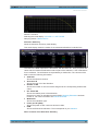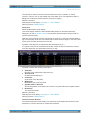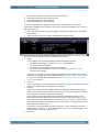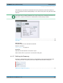
1
R&S®VSE-K10x (LTE Downlink) LTE Downlink Measurements User Manual (;ÚçÞ2) User Manual Test & Measurement 1176.8980.02 ─ 01 This manual applies to the R&S®VSE base software (1320.7500.02) version 1.10 and higher. This manual describes functionality of the following R&S®VSE options: ● R&S®VSE-K100 LTE FDD Measurement Application (1320.7545K02) ● R&S®VSE-K104 LTE FDD Measurement Application (1320.7568K02) The firmware of the instrument makes use of several valuable open source software packages. For information, see the "Open Source Acknowledgement" on the user documentation CD-ROM (included in delivery). Rohde & Schwarz would like to thank the open source community for their valuable contribution to embedded computing. © 2015 Rohde & Schwarz GmbH & Co. KG Mühldorfstr. 15, 81671 München, Germany Phone: +49 89 41 29 - 0 Fax: +49 89 41 29 12 164 E-mail: [email protected] Internet: www.rohde-schwarz.com Subject to change – Data without tolerance limits is not binding. R&S® is a registered trademark of Rohde & Schwarz GmbH & Co. KG. Trade names are trademarks of the owners. The following abbreviations are used throughout this manual: R&S®VSE is abbreviated as R&S VSE. R&S®VSE-K10x (LTE Downlink) Contents Contents 1 Preface.................................................................................................... 7 1.1 About this Manual......................................................................................................... 7 1.2 Documentation Overview............................................................................................. 7 1.3 Typographical Conventions.........................................................................................8 2 Welcome to the LTE Measurement Application................................ 10 2.1 Starting the LTE Measurement Application..............................................................10 2.2 Understanding the Display Information....................................................................10 3 Measurements and Result Displays...................................................13 3.1 Selecting Measurements............................................................................................ 13 3.2 Selecting Result Displays.......................................................................................... 13 3.3 Performing Measurements.........................................................................................14 3.4 I/Q Measurements....................................................................................................... 14 3.5 3GPP Test Scenarios.................................................................................................. 31 4 Configuration........................................................................................33 4.1 Configuring I/Q Measurements..................................................................................33 4.1.1 Configuration Overview.................................................................................................34 4.1.2 Defining Signal Characteristics..................................................................................... 35 4.1.3 Configuring MIMO Setups.............................................................................................40 4.1.4 Demodulating the PDSCH............................................................................................ 40 4.1.5 Configuring PDSCH Subframes....................................................................................42 4.1.6 Configuring the Synchronization Signal........................................................................ 48 4.1.7 Configuring the Reference Signal................................................................................. 49 4.1.8 Configuring the Positioning Reference Signal...............................................................49 4.1.9 Defining the PDSCH Resource Block Symbol Offset....................................................50 4.1.10 Configuring the PBCH...................................................................................................51 4.1.11 Configuring the PCFICH............................................................................................... 52 4.1.12 Configuring the PHICH..................................................................................................53 4.1.13 Configuring the PDCCH................................................................................................ 55 4.1.14 Configuring the EPDCCH..............................................................................................56 4.1.15 Configuring Shared Channels....................................................................................... 58 User Manual 1176.8980.02 ─ 01 3 R&S®VSE-K10x (LTE Downlink) Contents 4.1.16 Selecting the Input and Output Source......................................................................... 59 4.1.17 Defining the Frequency................................................................................................. 60 4.1.18 Defining Level Characteristics.......................................................................................61 4.1.19 Configuring the Data Capture....................................................................................... 63 4.1.20 Triggering Measurements............................................................................................. 65 4.1.21 Estimating Parameters..................................................................................................65 4.1.22 Compensating Measurement Errors............................................................................. 66 4.1.23 Configuring Demodulation Parameters......................................................................... 67 5 Analysis................................................................................................ 70 5.1 Configuring Tables / Numerical Results................................................................... 70 5.2 Evaluation Range........................................................................................................ 70 5.3 Scale.............................................................................................................................72 5.4 Result Settings............................................................................................................ 73 5.5 Markers........................................................................................................................ 74 6 Remote Control.................................................................................... 76 6.1 Overview of Remote Command Suffixes.................................................................. 76 6.2 Introduction................................................................................................................. 77 6.2.1 Conventions used in Descriptions.................................................................................77 6.2.2 Long and Short Form.................................................................................................... 78 6.2.3 Numeric Suffixes........................................................................................................... 78 6.2.4 Optional Keywords........................................................................................................ 79 6.2.5 Alternative Keywords.................................................................................................... 79 6.2.6 SCPI Parameters.......................................................................................................... 79 6.3 Remote Commands to Select the LTE Application..................................................82 6.4 Configuring the Screen Layout..................................................................................82 6.4.1 General Layout..............................................................................................................82 6.4.2 Configuring the Layout over all Channels..................................................................... 82 6.4.3 Configuring the Layout of a Channel.............................................................................87 6.5 Remote Commands to Read Trace Data...................................................................92 6.5.1 Using the TRACe[:DATA] Command............................................................................ 92 6.5.2 Remote Commands to Read Measurement Results...................................................104 6.6 Remote Commands to Read Numeric Results.......................................................105 6.6.1 Frame Results.............................................................................................................105 User Manual 1176.8980.02 ─ 01 4 R&S®VSE-K10x (LTE Downlink) Contents 6.6.2 Result for Selection..................................................................................................... 106 6.6.3 Marker Table............................................................................................................... 113 6.7 Remote Commands to Read Limit Check Results.................................................114 6.7.1 Checking Limits for Numerical Result Display............................................................ 114 6.8 Remote Commands to Configure the Application................................................. 119 6.8.1 General Configuration................................................................................................. 120 6.8.2 Configuring I/Q Measurements................................................................................... 120 6.9 Analysis..................................................................................................................... 158 6.9.1 Evaluation Range........................................................................................................158 6.9.2 Y-Axis Scale................................................................................................................161 6.9.3 Result Settings............................................................................................................ 162 A Annex: Reference...............................................................................164 A.1 Common R&S VSE Menus....................................................................................... 164 A.1.1 File Menu.................................................................................................................... 164 A.1.2 Window Menu............................................................................................................. 165 A.1.3 Help Menu...................................................................................................................166 A.2 LTE Measurement Menus.........................................................................................166 A.2.1 Input & Output Menu................................................................................................... 166 A.2.2 Meas Setup Menu....................................................................................................... 167 A.2.3 Trace Menu................................................................................................................. 167 A.2.4 Marker Menu............................................................................................................... 167 A.2.5 Limits Menu.................................................................................................................168 List of Commands..............................................................................169 Index....................................................................................................174 User Manual 1176.8980.02 ─ 01 5 R&S®VSE-K10x (LTE Downlink) User Manual 1176.8980.02 ─ 01 Contents 6 R&S®VSE-K10x (LTE Downlink) Preface About this Manual 1 Preface 1.1 About this Manual This User Manual describes information specific to measurements in the LTE measurement application. All other applications are described in the corresponding application manuals. The main focus in this manual is on the measurement results and the tasks required to obtain them. The following topics are included: ● Welcome to the R&S VSE Introduction to and getting familiar with the software ● Measurements and Results Descriptions of the measurement types available in the R&S VSE software ● Controlling Instruments and Capturing I/Q Data Methods of data acquisition and description of basic instrument control functions ● LTE Measurements Description of the settings and functions provided to analyze results with the software and the corresponding remote control commands ● Remote Commands for LTE Measurements Remote commands required to configure and perform measurements in a remote environment, sorted by tasks Remote commands required to set up the environment and to perform common tasks in the software, sorted by tasks Programming examples demonstrate the use of many commands and can usually be executed directly for test purposes ● List of Commands Alpahabetical list of all remote commands described in the manual ● Index 1.2 Documentation Overview The user documentation for the R&S VSE consists of the following parts: ● "Getting Started" printed manual ● Online Help system in the software ● CD-ROM including the following documentation: – Getting Started – User Manuals for base software and options – Service Manual – Release Notes – Data sheet and product brochures User Manual 1176.8980.02 ─ 01 7 R&S®VSE-K10x (LTE Downlink) Preface Typographical Conventions Online Help The Online Help is embedded in the software. It offers quick, context-sensitive access to the complete information needed for operation and programming. Online help is available using the icon on the toolbar of the R&S VSE. Getting Started This manual is delivered with the software in printed form and in PDF format on the CD. It provides the information needed to set up and start working with the software. Basic operations and handling are described. Safety information is also included. User Manuals User manuals are provided for the base software and each additional (software) option. The user manuals are available in PDF format - in printable form - on the CD-ROM delivered with the software. In the user manuals, all software functions are described in detail. Furthermore, they provide a complete description of the remote control commands with programming examples. The user manual for the base software provides basic information on operating the R&S VSE in general, and the I/Q Analyzer application in particular. Furthermore, the software functions that enhance the basic functionality for various applications are described here. An introduction to remote control is provided, as well as information on troubleshooting. In the individual application manuals, the specific software functions of the application are described in detail. For additional information on default settings and parameters, refer to the data sheets. Basic information on operating the R&S VSE is not included in the application manuals. Release Notes The release notes describe the installation of the software, new and modified functions, eliminated problems, and last minute changes to the documentation. The corresponding software version is indicated on the title page of the release notes. 1.3 Typographical Conventions The following text markers are used throughout this documentation: Convention Description "Graphical user interface elements" All names of graphical user interface elements on the screen, such as dialog boxes, menus, options, buttons, and softkeys are enclosed by quotation marks. KEYS Key names are written in capital letters. File names, commands, program code File names, commands, coding samples and screen output are distinguished by their font. User Manual 1176.8980.02 ─ 01 8 R&S®VSE-K10x (LTE Downlink) Preface Typographical Conventions Convention Description Input Input to be entered by the user is displayed in italics. Links Links that you can click are displayed in blue font. "References" References to other parts of the documentation are enclosed by quotation marks. User Manual 1176.8980.02 ─ 01 9 R&S®VSE-K10x (LTE Downlink) Welcome to the LTE Measurement Application Starting the LTE Measurement Application 2 Welcome to the LTE Measurement Application The R&S VSE-K100 and -K104 are firmware applications that add functionality to perform measurements on LTE signals according to the 3GPP standard to the R&S VSE. This user manual contains a description of the functionality that the application provides, including remote control operation. Functions that are not discussed in this manual are the same as in the Spectrum application and are described in the R&S VSE User Manual. The latest versions of the manuals are available for download at the product homepage. ● ● Starting the LTE Measurement Application.............................................................10 Understanding the Display Information................................................................... 10 2.1 Starting the LTE Measurement Application The LTE measurement application adds a new application to the R&S VSE. To activate the LTE application 1. Select the "Add Channel" function in the Sequence tool window. A dialog box opens that contains all operating modes and applications currently available in your R&S VSE. 2. Select the "LTE" item. The R&S VSE opens a new measurement channel for the LTE application. The application is started with the default settings. It can be configured in the "Overview" dialog box, which is displayed when you select the "Overview" softkey from the "Meas Setup" menu. For more information see chapter 4, "Configuration", on page 33. 2.2 Understanding the Display Information The following figure shows a measurement diagram during analyzer operation. All different information areas are labeled. They are explained in more detail in the following sections. User Manual 1176.8980.02 ─ 01 10 R&S®VSE-K10x (LTE Downlink) Welcome to the LTE Measurement Application Understanding the Display Information 1 1 2 3 4 5 = = = = = 2 3 4 5 Window title bar with information about the diagram and its traces Channel bar with measurement settings Diagram area Diagram footer with information about the contents of the diagram Color code for windows of the same channel (here: red) Channel bar information In the LTE measurement application, the R&S VSE shows the following settings: Table 2-1: Information displayed in the channel bar in the LTE measurement application Ref Level Reference level Att Mechanical and electronic RF attenuation Freq Frequency Mode LTE standard MIMO Number of Tx and Rx antennas in the measurement setup Capture Time Signal length that has been captured Frame Count Number of frames that have been captured Selected Subframe Subframe considered in the signal analysis In addition, the channel bar also displays information on instrument settings that affect the measurement results even though this is not immediately apparent from the display of the measured values (e.g. transducer or trigger settings). This information is displayed only when applicable for the current measurement. For details see the R&S VSE Getting Started manual. User Manual 1176.8980.02 ─ 01 11 R&S®VSE-K10x (LTE Downlink) Welcome to the LTE Measurement Application Understanding the Display Information Window title bar information The information in the window title bar depends on the result display. The "Constellation Diagram", for example, shows the number of points that have been measured. Status bar information Global instrument settings, the instrument status and any irregularities are indicated in the status bar beneath the diagram. Furthermore, the progress of the current operation is displayed in the status bar. Regarding the synchronization state, the application shows the following labels. ● Sync OK The synchronization was successful. The status bar is green. ● Sync Failed The synchronization was not successful. The status bar is red. There can be three different synchronization errors. – Sync Failed (Cyclic Prefix): The cyclic prefix correlation failed. – Sync Failed (P-SYNC): The P-SYNC correlation failed. – Sync Failed (S-SYNC): The S-SYNC correlation failed. User Manual 1176.8980.02 ─ 01 12 R&S®VSE-K10x (LTE Downlink) Measurements and Result Displays Selecting Measurements 3 Measurements and Result Displays The LTE measurement application measures and analyzes various aspects of an LTE signal. It features several measurements and result displays. Measurements represent different ways of processing the captured data during the digital signal processing. Result displays are different representations of the measurement results. They may be diagrams that show the results as a graph or tables that show the results as numbers. ● ● ● ● ● Selecting Measurements.........................................................................................13 Selecting Result Displays........................................................................................13 Performing Measurements......................................................................................14 I/Q Measurements...................................................................................................14 3GPP Test Scenarios..............................................................................................31 3.1 Selecting Measurements ► Select the "Select Meas" menu item from the "Meas Setup" menu. The application opens a dialog box that contains several buttons. Each button represents a set of result displays that thematically belong together and that have a particular display configuration. If these predefined display configurations do not suit your requirements you can add or remove result displays as you like. For more information about selecting result displays see chapter 3.2, "Selecting Result Displays", on page 13. Depending on the button you select, the application changes the way the R&S VSE captures and processes the raw signal data. ● When you select "EVM", the application processes the I/Q data of the signal. For more information on available I/Q result displays see chapter 3, "Measurements and Result Displays", on page 13. When you select one of the result displays available for I/Q measurements, you can combine the result displays available for I/Q measurements in any way. Remote command: CONFigure[:LTE]:MEASurement on page 120 3.2 Selecting Result Displays ► Select the "New Window" menu item from the "Window" menu or select a new winicon in the toolbar. Depending on the number of LTE channel you dow with the User Manual 1176.8980.02 ─ 01 13 R&S®VSE-K10x (LTE Downlink) Measurements and Result Displays Performing Measurements are currently using, there is a submenu that contains all available result displays for each LTE channel. In the default state of the application, it shows several conventional result displays. ● Capture Buffer ● EVM vs Carrier ● Power Spectrum ● Result Summary ● Constellation Diagram From that predefined state, add and remove result displays to the channels as you like from the "Window" menu. Remote command: LAYout:ADD[:WINDow]? on page 87 Note that you can customize the contents of some numerical result displays. For more information see chapter 5.1, "Configuring Tables / Numerical Results", on page 70. 3.3 Performing Measurements By default, the application measures the signal continuously. In "Continuous Sweep" mode, the application captures and analyzes the data again and again. The amount of data depends on the capture time (I/Q measurements) or the sweep time (frequency sweep measurements). In "Single Sweep" mode, the application stops measuring after it has captured the data once. The amount of data again depends on the capture time or the sweep time. You can also repeat a measurement based on the data that has already been captured with the "Refresh" function. This is useful if you want to apply different modulation settings to the same I/Q data, for example. For more information see the documentation of the R&S VSE. 3.4 I/Q Measurements You can select the result displays from the evaluation bar and arrange them as you like with the SmartGrid functionality. Capture Buffer...............................................................................................................15 EVM vs Carrier..............................................................................................................16 EVM vs Symbol.............................................................................................................17 EVM vs RB....................................................................................................................18 EVM vs Subframe......................................................................................................... 19 Frequency Error vs Symbol...........................................................................................19 Power Spectrum............................................................................................................20 Power vs Resource Block PDSCH................................................................................20 User Manual 1176.8980.02 ─ 01 14 R&S®VSE-K10x (LTE Downlink) Measurements and Result Displays I/Q Measurements Power vs Resource Block RS....................................................................................... 21 Channel Flatness.......................................................................................................... 21 Channel Group Delay....................................................................................................22 Channel Flatness Difference.........................................................................................22 Constellation Diagram...................................................................................................23 CCDF............................................................................................................................ 23 Allocation Summary...................................................................................................... 24 Bit Stream..................................................................................................................... 25 Channel Decoder Results............................................................................................. 25 EVM vs Sym x Carr.......................................................................................................27 Power vs Symbol x Carrier............................................................................................28 Allocation ID vs Symbol x Carrier..................................................................................28 Result Summary............................................................................................................29 Marker Table................................................................................................................. 31 Capture Buffer The Capture Buffer result display shows the complete range of captured data for the last data capture. The x-axis represents time. The maximum value of the x-axis is equal to the Capture Time. The y-axis represents the amplitude of the captured I/Q data in dBm (for RF input). The bar at the bottom of the diagram represents the frame that is currently analyzed. Different colors indicate the OFDM symbol type. ● ● ● ● Indicates the data stream. Indicates the reference signal and data. Indicates the P-SYNC and data. Indicates the S-SYNC and data. A green vertical line at the beginning of the green bar in the Capture Buffer display marks the subframe start. Additionally, the diagram contains the "Start Offset" value. This value is the time difference between the subframe start and capture buffer start. When you zoom into the diagram, you will see that the bar may be interrupted at certain positions. Each small bar indicates the useful parts of the OFDM symbol. User Manual 1176.8980.02 ─ 01 15 R&S®VSE-K10x (LTE Downlink) Measurements and Result Displays I/Q Measurements Remote command: Selecting the result display: LAY:ADD ? '1',LEFT,CBUF Querying results: TRACe:DATA? Querying the subframe start offset: FETCh:SUMMary:TFRame? on page 112 EVM vs Carrier Starts the EVM vs Carrier result display. This result display shows the Error Vector Magnitude (EVM) of the subcarriers. With the help of a marker, you can use it as a debugging technique to identify any subcarriers whose EVM is too high. The results are based on an average EVM that is calculated over the resource elements for each subcarrier. This average subcarrier EVM is determined for each analyzed subframe in the capture buffer. If you analyze all subframes, the result display contains three traces. ● Average EVM This trace shows the subcarrier EVM averaged over all subframes. ● Minimum EVM This trace shows the lowest (average) subcarrier EVM that has been found over the analyzed subframes. ● Maximum EVM This trace shows the highest (average) subcarrier EVM that has been found over the analyzed subframes. If you select and analyze one subframe only, the result display contains one trace that shows the subcarrier EVM for that subframe only. Average, minimum and maximum values in that case are the same. For more information see "Subframe Selection" on page 70 The x-axis represents the center frequencies of the subcarriers. On the y-axis, the EVM is plotted either in % or in dB, depending on the EVM Unit. User Manual 1176.8980.02 ─ 01 16 R&S®VSE-K10x (LTE Downlink) Measurements and Result Displays I/Q Measurements Remote command: Selecting the result display: LAY:ADD ? '1',LEFT,EVCA Querying results: TRACe:DATA? EVM vs Symbol Starts the EVM vs Symbol result display. This result display shows the Error Vector Magnitude (EVM) of the OFDM symbols. You can use it as a debugging technique to identify any symbols whose EVM is too high. The results are based on an average EVM that is calculated over all subcarriers that are part of a particular OFDM symbol. This average OFDM symbol EVM is determined for all OFDM symbols in each analyzed subframe. If you analyze all subframes, the result display contains three traces. ● Average EVM This trace shows the OFDM symbol EVM averaged over all subframes. ● Minimum EVM This trace shows the lowest (average) OFDM symbol EVM that has been found over the analyzed subframes. ● Maximum EVM This trace shows the highest (average) OFDM symbol EVM that has been found over the analyzed subframes. If you select and analyze one subframe only, the result display contains one trace that shows the OFDM symbol EVM for that subframe only. Average, minimum and maximum values in that case are the same. For more information see "Subframe Selection" on page 70 The x-axis represents the OFDM symbols, with each symbol represented by a dot on the line. The number of displayed symbols depends on the Subframe Selection and the length of the cyclic prefix. Any missing connections from one dot to another mean that the R&S VSE could not determine the EVM for that symbol. In case of TDD signals, the result display does not show OFDM symbols that are not part of the measured link direction. On the y-axis, the EVM is plotted either in % or in dB, depending on the EVM Unit. User Manual 1176.8980.02 ─ 01 17 R&S®VSE-K10x (LTE Downlink) Measurements and Result Displays I/Q Measurements Remote command: Selecting the result display: LAY:ADD ? '1',LEFT,EVSY Querying results: TRACe:DATA? EVM vs RB Starts the EVM vs RB result display. This result display shows the Error Vector Magnitude (EVM) for all resource blocks that can be occupied by the PDSCH. The results are based on an average EVM that is calculated over all resource elements in the resource block. This average resource block EVM is determined for each analyzed subframe. If you analyze all subframes, the result display contains three traces. ● Average EVM This trace shows the resource block EVM averaged over all subframes. ● Minimum EVM This trace shows the lowest (average) resource block EVM that has been found over the analyzed subframes. ● Maximum EVM This trace shows the highest (average) resource block EVM that has been found over the analyzed subframes. If you select and analyze one subframe only, the result display contains one trace that shows the resource block EVM for that subframe only. Average, minimum and maximum values in that case are the same. For more information see "Subframe Selection" on page 70 The x-axis represents the PDSCH resource blocks. On the y-axis, the EVM is plotted either in % or in dB, depending on the EVM Unit. Remote command: Selecting the result display: LAY:ADD ? '1',LEFT,EVRP Querying results: TRACe:DATA? User Manual 1176.8980.02 ─ 01 18 R&S®VSE-K10x (LTE Downlink) Measurements and Result Displays I/Q Measurements EVM vs Subframe Starts the EVM vs Subframe result display. This result display shows the Error Vector Magnitude (EVM) for each subframe. You can use it as a debugging technique to identify a subframe whose EVM is too high. The result is an average over all subcarriers and symbols of a specific subframe. The x-axis represents the subframes, with the number of displayed subframes being 10. On the y-axis, the EVM is plotted either in % or in dB, depending on the EVM Unit. Remote command: Selecting the result display: LAY:ADD ? '1',LEFT,EVSU Querying results: TRACe:DATA? Frequency Error vs Symbol Starts the Frequency Error vs Symbol result display. This result display shows the Frequency Error on symbol level. You can use it as a debugging technique to identify any frequency errors within symbols. The result is an average over all subcarriers. The x-axis represents the OFDM symbols, with each symbol represented by a dot on the line. The number of displayed symbols depends on the Subframe Selection and the length of the cyclic prefix. Any missing connections from one dot to another mean that the R&S VSE could not determine the frequency error for that symbol. On the y-axis, the frequency error is plotted in Hz. Note that the variance of the measurement results in this result display may be much higher compared to the frequency error display in the Result Summary, depending on the PDSCH and control channel configuration. The potential difference is caused by the number of available resource elements for the measurement on symbol level. User Manual 1176.8980.02 ─ 01 19 R&S®VSE-K10x (LTE Downlink) Measurements and Result Displays I/Q Measurements Remote command: Selecting the result display: LAY:ADD ? '1',LEFT,FEVS Querying results: TRACe:DATA? Power Spectrum Starts the Power Spectrum result display. This result display shows the power density of the complete capture buffer in dBm/Hz. The displayed bandwidth depends on bandwidth or number of resource blocks you have set. For more information see "Channel Bandwidth / Number of Resource Blocks" on page 37. The x-axis represents the frequency. On the y-axis the power level is plotted. Remote command: Selecting the result display: LAY:ADD ? '1',LEFT,PSPE Querying results: TRACe:DATA? Power vs Resource Block PDSCH Starts the Power vs Resource Block PDSCH result display. This result display shows the power of the physical downlink shared channel per resource element averaged over one resource block. By default, three traces are shown. One trace shows the average power. The second and the third trace show the minimum and maximum powers respectively. You can select to display the power for a specific subframe in the Subframe Selection dialog box. In that case, the application shows the powers of that subframe only. The x-axis represents the resource blocks. The displayed number of resource blocks depends on the channel bandwidth or number of resource blocks you have set. On the y-axis, the power is plotted in dBm. User Manual 1176.8980.02 ─ 01 20 R&S®VSE-K10x (LTE Downlink) Measurements and Result Displays I/Q Measurements Remote command: Selecting the result display: LAY:ADD ? '1',LEFT,PVRP Querying results: TRACe:DATA? Power vs Resource Block RS Starts the Power vs Resource Block RS result display. This result display shows the power of the reference signal per resource element averaged over one resource block. By default, three traces are shown. One trace shows the average power. The second and the third trace show the minimum and maximum powers respectively. You can select to display the power for a specific subframe in the Subframe Selection dialog box. In that case, the application shows the power of that subframe only. The x-axis represents the resource blocks. The displayed number of resource blocks depends on the channel bandwidth or number of resource blocks you have set. On the y-axis, the power is plotted in dBm. Remote command: Selecting the result display: LAY:ADD ? '1',LEFT,PVRR Querying results: TRACe:DATA? Channel Flatness Starts the Channel Flatness result display. This result display shows the relative power offset caused by the transmit channel. The currently selected subframe depends on your selection. The x-axis represents the frequency. On the y-axis, the channel flatness is plotted in dB. User Manual 1176.8980.02 ─ 01 21 R&S®VSE-K10x (LTE Downlink) Measurements and Result Displays I/Q Measurements Remote command: Selecting the result display: LAY:ADD ? '1',LEFT,FLAT Querying results: TRACe:DATA? Channel Group Delay Starts the Channel Group Delay result display. This result display shows the group delay of each subcarrier. The currently selected subframe depends on your selection. The x-axis represents the frequency. On the y-axis, the group delay is plotted in ns. Remote command: Selecting the result display: LAY:ADD ? '1',LEFT,GDEL Querying results: TRACe:DATA? Channel Flatness Difference Starts the Channel Flatness Difference result display. This result display shows the level difference in the spectrum flatness result between two adjacent physical subcarriers. The currently selected subframe depends on your selection. The x-axis represents the frequency. On the y-axis, the power is plotted in dB. User Manual 1176.8980.02 ─ 01 22 R&S®VSE-K10x (LTE Downlink) Measurements and Result Displays I/Q Measurements Remote command: Selecting the result display: LAY:ADD ? '1',LEFT,FDIF Querying results: TRACe:DATA? Constellation Diagram Starts the Constellation Diagram result display. This result display shows the inphase and quadrature phase results and is an indicator of the quality of the modulation of the signal. In the default state, the result display evaluates the full range of the measured input data. You can filter the results by changing the evaluation range. The constellation diagram also contains information about the current evaluation range. In addition, it shows the number of points that are displayed in the diagram. Remote command: Selecting the result display: LAY:ADD ? '1',LEFT,CONS Querying results: TRACe:DATA? CCDF Starts the Complementary Cumulative Distribution Function (CCDF) result display. This result display shows the probability of an amplitude exceeding the mean power. For the measurement, the complete capture buffer is used. The x-axis represents the power relative to the measured mean power. On the y-axis, the probability is plotted in %. User Manual 1176.8980.02 ─ 01 23 R&S®VSE-K10x (LTE Downlink) Measurements and Result Displays I/Q Measurements Remote command: Selecting the result display: LAY:ADD ? '1',LEFT,CCDF Querying results: TRACe:DATA? Allocation Summary Starts the Allocation Summary result display. This result display shows the results of the measured allocations in tabular form. The rows in the table represent the allocations, with allocation ALL being a special allocation that summarizes all allocations that are part of the subframe. A set of allocations form a subframe. The subframes are separated by a dashed line. The columns of the table contain the following information: ● ● ● ● ● ● ● Subframe Shows the subframe number. Allocation ID Shows the type / ID of the allocation. Number of RB Shows the number of resource blocks assigned to the corresponding PDSCH allocation. Rel. Power/dB Shows the relative power of the allocation. Note that no power is calculated for the PHICH if Boosting Estimation has been turned on. For more information see PHICH Rel Power. Modulation Shows the modulation type. Power per RE [dBm] Shows the power of each resource element in dBm. EVM Shows the EVM of the allocation. The unit depends on your selection. Note: Contents of the Allocation Summary User Manual 1176.8980.02 ─ 01 24 R&S®VSE-K10x (LTE Downlink) Measurements and Result Displays I/Q Measurements The number of columns shown in the Allocation Summary is variable. To add or remove a column, click on the header row of the table once. The application opens a dialog box to select the columns which you'd like to display. Remote command: Selecting the result display: LAY:ADD ? '1',LEFT,ASUM Querying results: TRACe:DATA? Bit Stream Starts the Bit Stream result display. This result display shows the demodulated data stream for each data allocation. Depending on the Bit Stream Format, the numbers represent either bits (bit order) or symbols (symbol order). Selecting symbol format shows the bit stream as symbols. In that case the bits belonging to one symbol are shown as hexadecimal numbers with two digits. In the case of bit format, each number represents one raw bit. Symbols or bits that are not transmitted are represented by a "-". If a symbol could not be decoded because the number of layers exceeds the number of receive antennas, the application shows a "#" sign. The table contains the following information: ● ● ● ● ● ● Subframe Number of the subframe the bits belong to. Allocation ID Channel the bits belong to. Codeword Code word of the allocation. Modulation Modulation type of the channels. Symbol Index or Bit Index Shows the position of the table row's first bit or symbol within the complete stream. Bit Stream The actual bit stream. Remote command: Selecting the result display: LAY:ADD ? '1',LEFT,BSTR Querying results: TRACe:DATA? Channel Decoder Results The Channel Decoder result display is a numerical result display that shows the characteristics of various channels for a particular subframe. User Manual 1176.8980.02 ─ 01 25 R&S®VSE-K10x (LTE Downlink) Measurements and Result Displays I/Q Measurements ● ● ● ● Protocol information of the PBCH, PCFICH and PHICH. Information about the DCIs in the PDCCH. Decoded bitstream for each PDCCH. Decoded bitstream for each PDSCH. The size of the table thus depends on the number of subframes in the signal. Note that a complete set of results for the control channels is available only under certain circumstances. ● ● The corresponding control channel (PBCH, PCFICH or PHICH) has to be present and enabled. Each channel must have a certain configuration (see list below). For each channel, the table shows a different set of values. ● PBCH For the PBCH, the Channel Decoder provides the following results. – the MIMO configuration of the DUT (1, 2 or 4 TX antennas) – the Transmission bandwidth – the Duration of the PHICH (normal or extended) – the PHICH resource which is the same as PHICH Ng (1/6, 1/2, 1 or 2) – System frame number ● ● ● If the CRC is not valid, a corresponding message is shown instead of the results. Results for the PBCH can only be determined if the PHICH Duration or the PHICH N_g are automatically determined ("Auto") or if automatic decoding of all control channels is turned on. PCFICH For the PCFICH, the Channel Decoder provides the number of OFDM symbols that are used for PDCCH at the beginning of a subframe. PHICH The PHICH carries the hybrid-ARQ ACK/NACK. Multiple PHICHs mapped to the same set of resource elements are a PHICH group. The PHICHs within one group are separated by different orthogonal sequences. For the PHICH, the Channel Decoder provides the ACK/NACK pattern for the PHICH group and the relative power for each PHICH in the PHICH group. Each line in the result table represents one PHICH group. The columns on the left show the ACK/NACK pattern of the PHICH group. The columns on the right show the relative powers for each PHICH. If a PHICH is not transmitted, the table contains a "-" sign. Otherwise, the ACK/ NACK pattern is either a "1" (acknowledgement) or a "0" (not acknowledged). The relative power is a numeric value in dB. PDCCH User Manual 1176.8980.02 ─ 01 26 R&S®VSE-K10x (LTE Downlink) Measurements and Result Displays I/Q Measurements For each PDCCH that has been detected, the Channel Decoder shows several results. Each line in the table represents one PDCCH. – RNTI – DCI Format Shows the Downlink Control Information (DCI) format. The DCI contains information about the resource assignment for the UEs. The following DCI formats are supported: 0, 1, 1A, 1B, 1C, 2, 2A, 2C, 2D, 3, 3A. The DCI format is determined by the length of the DCI. Because they have the same length, the Channel Decoder is not able to distinguish formats 0, 3 and 3A. Note that a DCI that consist of only zero bits cannot be decoded. – PDCCH format used to transmit the DCI – CCE Offset The CCE Offset represents the position of the current DCI in the PDCCH bit stream. – Rel. Power Relative power ofthe corresponding PDCCH. ● Results for the PDCCH can only be determined if the PDSCH subframe configuration is detected by the "PDCCH Protocol" or if automatic decoding of all control channels is turned on. PDSCH For each decoded PDSCH allocation there is a PDCCH DCI. The DCI contains parameters that are required for the decoding process. If the channel could be decoded successfully, the result display shows the bit stream for each codeword. If the Cyclic Redundancy Check (CRC) fails, the result display shows an error message instead. Results for the PDSCH can only be determined if the PDSCH subframe configuration is detected by the "PDCCH Protocol" or if automatic decoding of all control channels is turned on. Remote command: Selecting the result display: LAY:ADD ? '1',LEFT,CDEC Querying results: TRACe:DATA? EVM vs Sym x Carr The EVM vs Symbol x Carrier shows the EVM for each carrier in each symbol. The horizontal axis represents the symbols. The vertical axis represents the carriers. Different colors in the diagram area represent the EVM. The color map for the power levels is provided above the diagram area. User Manual 1176.8980.02 ─ 01 27 R&S®VSE-K10x (LTE Downlink) Measurements and Result Displays I/Q Measurements Remote command: Selecting the result display: LAY:ADD ? '1',LEFT,EVSC Querying results: TRACe:DATA? Power vs Symbol x Carrier The Power vs Symbol x Carrier shows the power for each carrier in each symbol. The horizontal axis represents the symbols. The vertical axis represents the carriers. Different colors in the diagram area represent the power. The color map for the power levels is provided above the diagram area. Remote command: Selecting the result display: LAY:ADD ? '1',LEFT,PVSC Querying results: TRACe:DATA? Allocation ID vs Symbol x Carrier The Allocation ID vs. Symbol X Carrier display shows the allocation ID of each carrier in each symbol of the received signal. Each type of allocation is represented by a different color. Use a marker to get more information about the type of allocation. User Manual 1176.8980.02 ─ 01 28 R&S®VSE-K10x (LTE Downlink) Measurements and Result Displays I/Q Measurements Remote command: Selecting the result display: LAY:ADD ? '1',LEFT,AISC Querying results: TRACe:DATA? Result Summary The Result Summary shows all relevant measurement results in numerical form, combined in one table. Remote command: LAY:ADD ? '1',LEFT,RSUM Contents of the result summary The table is split in two parts. The first part shows results that refer to the complete frame. For each result, the minimum, mean and maximum values are displayed. It also indicates limit check results where available. The font of 'Pass' results is green and that of 'Fail' results is red. In addition to the red font, the application also puts a red star ( failed results. User Manual 1176.8980.02 ─ 01 ) in front of 29 R&S®VSE-K10x (LTE Downlink) Measurements and Result Displays I/Q Measurements EVM PDSCH QPSK Shows the EVM for all QPSK-modulated resource elements of the PDSCH channel in the analyzed frame. FETCh[:CC<cci>]:SUMMary:EVM:DSQP[:AVERage]? on page 105 EVM PDSCH 16QAM Shows the EVM for all 16QAM-modulated resource elements of the PDSCH channel in the analyzed frame. FETCh[:CC<cci>]:SUMMary:EVM:DSST[:AVERage]? on page 105 EVM PDSCH 64QAM Shows the EVM for all 64QAM-modulated resource elements of the PDSCH channel in the analyzed frame. FETCh[:CC<cci>]:SUMMary:EVM:DSSF[:AVERage]? on page 106 By default, all EVM results are in %. To view the EVM results in dB, change the EVM Unit. The second part of the table shows results that refer to a specifc selection of the frame. The statistic is always evaluated over the subframes. The header row of the table contains information about the selection you have made (like the subframe). EVM All Shows the EVM for all resource elements in the analyzed frame. FETCh[:CC<cci>]:SUMMary:EVM[:ALL][:AVERage]? on page 107 EVM Phys Channel Shows the EVM for all physical channel resource elements in the analyzed frame. A physical channel corresponds to a set of resource elements carrying information from higher layers. PDSCH, PBCH or PDCCH, for example, are physical channels. For more information see 3GPP 36.211. FETCh[:CC<cci>]:SUMMary:EVM:PCHannel[:AVERage]? on page 108 EVM Phys Signal Shows the EVM for all physical signal resource elements in the analyzed frame. The reference signal, for example, is a physical signal. For more information see 3GPP 36.211. FETCh[:CC<cci>]:SUMMary:EVM:PSIGnal[:AVERage]? on page 108 Frequency Error Shows the difference in the measured center frequency and the reference center frequency. FETCh[:CC<cci>]:SUMMary:FERRor[:AVERage]? on page 109 Sampling Error Shows the difference in measured symbol clock and reference symbol clock relative to the system sampling rate. FETCh[:CC<cci>]:SUMMary:SERRor[:AVERage]? on page 112 I/Q Offset Shows the power at spectral line 0 normalized to the total transmitted power. FETCh[:CC<cci>]:SUMMary:IQOFfset[:AVERage]? on page 109 I/Q Gain Imbalance Shows the logarithm of the gain ratio of the Q-channel to the I-channel. FETCh[:CC<cci>]:SUMMary:GIMBalance[:AVERage]? on page 109 I/Q Quadrature Error Shows the measure of the phase angle between Q-channel and I-channel deviating from the ideal 90 degrees. FETCh[:CC<cci>]:SUMMary:QUADerror[:AVERage]? on page 111 User Manual 1176.8980.02 ─ 01 30 R&S®VSE-K10x (LTE Downlink) Measurements and Result Displays 3GPP Test Scenarios RSTP Shows the reference signal transmit power as defined in 3GPP TS 36.141. It is required for the "DL RS Power" test. It is an average power and accumulates the powers of the reference symbols within a subframe divided by the number of reference symbols within a subframe. FETCh[:CC<cci>]:SUMMary:RSTP[:AVERage]? on page 111 OSTP Shows the OFDM symbol transmit power as defined in 3GPP TS 36.141. It accumulates all subcarrier powers of the 4th OFDM symbol. The 4th (out of 14 OFDM symbols within a subframe (in case of frame type 1, normal CP length)) contains exclusively PDSCH. FETCh[:CC<cci>]:SUMMary:OSTP[:AVERage]? on page 110 Power Shows the average time domain power of the analyzed signal. FETCh[:CC<cci>]:SUMMary:POWer[:AVERage]? on page 110 Crest Factor Shows the peak-to-average power ratio of captured signal. FETCh[:CC<cci>]:SUMMary:CRESt[:AVERage]? on page 107 Marker Table Displays a table with the current marker values for the active markers. Remote command: LAY:ADD? '1',RIGH, MTAB, see LAYout:ADD[:WINDow]? on page 87 Results: CALCulate<n>:MARKer<m>:X on page 113 CALCulate<n>:MARKer<m>:Y? on page 114 3.5 3GPP Test Scenarios 3GPP defines several test scenarios for measuring base stations. These test scenarios are described in detail in 3GPP TS 36.141. The following table provides an overview which measurements available in the LTE application are suited to use for the test scenarios in the 3GPP documents. Table 3-1: Test scenarios for E-TMs as defined by 3GPP (3GPP TS 36.141) Test Model Test scenario Test described in Measurement E-TM1.1 Base station output power chapter 6.2 Power (➙ Result Summary) Transmit On/Off power chapter 6.4 On/Off Power DL RS power chapter 6.5.4 RSTP (➙ Result Summary) Time alignment chapter 6.5.3 Time Alignment Error User Manual 1176.8980.02 ─ 01 31 R&S®VSE-K10x (LTE Downlink) Measurements and Result Displays 3GPP Test Scenarios Test Model E-TM1.2 E-TM2 E-TM3.1 E-TM3.2 E-TM3.3 Test scenario Test described in Measurement Transmitter intermodulation chapter 6.7 ACLR Occupied bandwidth chapter 6.6.1 Occupied Bandwidth1 ACLR chapter 6.6.2 ACLR Operating band unwanted emissions chapter 6.6.3 Spectrum Emission Mask Transmitter spurious emissions chapter 6.6.4 Spurious Emissions1 ACLR chapter 6.6.2 ACLR Operating band unwanted emissions chapter 6.6.2 Spectrum Emission Mask RE power control dynamic range chapter 6.3.1 Power results Frequency error chapter 6.5.1 Frequency Error (➙ Result Summary) Total power dynamic range chapter 6.3.2 OSTP (➙ Result Summary) Error Vector Magnitude chapter 6.5.2 EVM results RE power control dynamic range chapter 6.3.1 Power results Total power dynamic range chapter 6.3.2 OSTP (➙ Result Summary) Frequency error chapter 6.5.1 Frequency Error (➙ Result Summary) Error Vector Magnitude chapter 6.5.2 EVM results RE power control dynamic range chapter 6.3.1 Power results Frequency error chapter 6.5.1 Frequency Error (➙ Result Summary) Error Vector Magnitude chapter 6.5.2 EVM results RE power control dynamic range chapter 6.3.1 Power results Frequency error chapter 6.5.1 Frequency Error (➙ Result Summary) Error Vector Magnitude chapter 6.5.2 EVM results 1these measurements are available in the Spectrum application of the Rohde & Schwarz signal and spectrum analyzers (for example the R&S FSW) User Manual 1176.8980.02 ─ 01 32 R&S®VSE-K10x (LTE Downlink) Configuration Configuring I/Q Measurements 4 Configuration LTE measurements require a special application on the R&S VSE, which you activate using the MODE key on the front panel. When you start the LTE application, the R&S VSE starts to measure the input signal with the default configuration or the configuration of the last measurement (when you haven't performed a preset since then). Automatic refresh of preview and visualization in dialog boxes after configuration changes The R&S VSE supports you in finding the correct measurement settings quickly and easily - after each change in settings in dialog boxes, the preview and visualization areas are updated immediately and automatically to reflect the changes. Thus, you can see if the setting is appropriate or not before accepting the changes. Unavailable menus Note that the "Limits" and "Trace" menus have no contents and no function in the LTE application. ● Configuring I/Q Measurements............................................................................... 33 4.1 Configuring I/Q Measurements ● ● ● ● ● ● ● ● ● ● ● ● ● ● ● ● ● ● ● ● Configuration Overview...........................................................................................34 Defining Signal Characteristics............................................................................... 35 Configuring MIMO Setups.......................................................................................40 Demodulating the PDSCH...................................................................................... 40 Configuring PDSCH Subframes..............................................................................42 Configuring the Synchronization Signal.................................................................. 48 Configuring the Reference Signal........................................................................... 49 Configuring the Positioning Reference Signal.........................................................49 Defining the PDSCH Resource Block Symbol Offset..............................................50 Configuring the PBCH.............................................................................................51 Configuring the PCFICH......................................................................................... 52 Configuring the PHICH............................................................................................53 Configuring the PDCCH.......................................................................................... 55 Configuring the EPDCCH........................................................................................56 Configuring Shared Channels.................................................................................58 Selecting the Input and Output Source................................................................... 59 Defining the Frequency........................................................................................... 60 Defining Level Characteristics.................................................................................61 Configuring the Data Capture................................................................................. 63 Triggering Measurements....................................................................................... 65 User Manual 1176.8980.02 ─ 01 33 R&S®VSE-K10x (LTE Downlink) Configuration Configuring I/Q Measurements ● ● ● Estimating Parameters............................................................................................65 Compensating Measurement Errors....................................................................... 66 Configuring Demodulation Parameters................................................................... 67 4.1.1 Configuration Overview Throughout the measurement channel configuration, an overview of the most important currently defined settings is provided in the "Overview". The "Overview" is displayed when you select the "Overview" menu item from the "Meas Setup" menu. In addition to the main measurement settings, the "Overview" provides quick access to the main settings dialog boxes. The individual configuration steps are displayed in the order of the data flow. Thus, you can easily configure an entire measurement channel from input over processing to output and analysis by stepping through the dialog boxes as indicated in the "Overview". In particular, the "Overview" provides quick access to the following configuration dialog boxes (listed in the recommended order of processing): 1. Signal Description See chapter 4.1.2, "Defining Signal Characteristics", on page 35. 2. Input / Frontend See chapter 4.1.16, "Selecting the Input and Output Source", on page 59. 3. Trigger / Signal Capture See chapter 4.1.20, "Triggering Measurements", on page 65. See chapter 4.1.19, "Configuring the Data Capture", on page 63 4. Estimation / Tracking See chapter 4.1.22, "Compensating Measurement Errors", on page 66. 5. Demodulation See chapter 4.1.23, "Configuring Demodulation Parameters", on page 67. 6. Evaluation Range See chapter 5.2, "Evaluation Range", on page 70. 7. Analysis See chapter 5, "Analysis", on page 70. User Manual 1176.8980.02 ─ 01 34 R&S®VSE-K10x (LTE Downlink) Configuration Configuring I/Q Measurements 8. Display Configuration See chapter 3, "Measurements and Result Displays", on page 13. In addition, the dialog box provides the "Select Measurement" button that serves as a shortcut to select the measurement type. To configure settings ► Select any button in the "Overview" to open the corresponding dialog box. Select a setting in the channel bar (at the top of the measurement channel tab) to change a specific setting. Preset Channel Select the "Preset Channel" button in the lower lefthand corner of the "Overview" to restore all measurement settings in the current channel to their default values. Remote command: SYSTem:PRESet:CHANnel[:EXECute] on page 120 Select Measurement Opens a dialog box to select the type of measurement. Using this button has the same effect as selecting the "Select Measurement" menu item in the "Meas Setup" menu. For more information see chapter 3.1, "Selecting Measurements", on page 13. Remote command: CONFigure[:LTE]:MEASurement on page 120 Specifics for The measurement channel may contain several windows for different results. Thus, the settings indicated in the "Overview" and configured in the dialog boxes vary depending on the selected window. Select an active window from the "Specifics for" selection list that is displayed in the "Overview" and in all window-specific configuration dialog boxes. The "Overview" and dialog boxes are updated to indicate the settings for the selected window. 4.1.2 Defining Signal Characteristics The general signal characteristics contain settings to describe the general physical attributes of the signal. They are part of the "Signal Description" tab of the "Signal Description" dialog box. To define signal characteristics Signal characteristics settings can be defined in the "Signal Description" dialog box. 1. Select "Signal Description" from the "Overview" dialog box. 2. Press the MEAS CONFIG key and select the "Signal Description" softkey. User Manual 1176.8980.02 ─ 01 35 R&S®VSE-K10x (LTE Downlink) Configuration Configuring I/Q Measurements Selecting the LTE Mode................................................................................................36 Using Test Models........................................................................................................ 36 Channel Bandwidth / Number of Resource Blocks....................................................... 37 Cyclic Prefix.................................................................................................................. 37 Configuring TDD Frames.............................................................................................. 38 └ TDD UL/DL Allocations................................................................................... 38 └ Conf. of Special Subframe.............................................................................. 38 Configuring the Physical Layer Cell Identity..................................................................39 Selecting the LTE Mode The standard defines the LTE mode you are testing. The choices you have depend on the set of options you have installed. ● ● Option xxx-K100 enables testing of 3GPP LTE FDD signals on both uplink and downlink Option xxx-K104 enables testing of 3GPP LTE MIMO signals on both uplink and downlink FDD and TDD are duplexing methods. ● FDD mode uses different frequencies for the uplink and the downlink. ● TDD mode uses the same frequency for the uplink and the downlink. Downlink (DL) and Uplink (UL) describe the transmission path. ● Downlink is the transmission path from the base station to the user equipment. The physical layer mode for the downlink is always OFDMA. ● Uplink is the transmission path from the user equipment to the base station. The physical layer mode for the uplink is always SC-FDMA. Remote command: Link direction: CONFigure[:LTE]:LDIRection on page 124 Duplexing mode: CONFigure[:LTE]:DUPLexing on page 121 Using Test Models Test models are descriptions of LTE signals that you can use for particular test scenarios. The "Test Models" dialog box contains functionality to select, manage and create test models. ● "Specification" The "Specification" tab contains predefined test models as defined by 3GPP. Predefined test models are supported in downlink mode. ● "User Defined" The "User Defined" tab contains functionality to manage custom test models. Custom test models are supported in downlink and uplink mode. User Manual 1176.8980.02 ─ 01 36 R&S®VSE-K10x (LTE Downlink) Configuration Configuring I/Q Measurements To create a custom test model, describe a signal as required and then save it via the "Test Models" dialog box. Here, you can also restore custom test models and delete ones you do not need anymore. Predefined test models (E-TM) In case of downlink signals, the 3GPP standard (TS 36.141) already defines several EUTRA test models (E-TM) for specific test scenarios. These test models are split into three main groups (E-TM1, E-TM2 and E-TM3) and are defined by the following characteristics. ● single antenna port, single code word, single layer and no precoding ● duration of one frame ● normal cyclic prefix ● localized virtual resource blocks, no intra-subframe hopping for PDSCH ● UE-specific reference signal not used The data content of the physical channels and signals are defined in the 3GPP standard. Each E-TM is defined for for all bandwidths defined in the standard (1.4 MHz / 3 MHz / 5 MHz / 10 MHz / 15 MHz / 20 MHz). More information. Remote command: MMEMory:LOAD:TMOD:DL on page 125 Channel Bandwidth / Number of Resource Blocks Specifies the channel bandwidth and number of resource blocks (RB). The channel bandwidth and number of resource blocks (RB) are interdependent. Currently, the LTE standard recommends six bandwidths (see table below). The application also calculates the FFT size, sampling rate, occupied bandwidth and occupied carriers from the channel bandwidth. Those are read only. Channel Bandwidth [MHz] 1.4 3 5 10 15 20 Number of Resource Blocks 6 15 25 50 75 100 Sample Rate [MHz] 1.92 3.84 7.68 15.36 30.72 30.72 FFT Size 128 256 512 1024 2048 2048 The application shows the currently selected LTE mode (including the bandwidth) in the channel bar. Remote command: CONFigure[:LTE]:DL[:CC<cci>]:BW on page 122 Cyclic Prefix The cyclic prefix serves as a guard interval between OFDM symbols to avoid interferences. The standard specifies two cyclic prefix modes with a different length each. The cyclic prefix mode defines the number of OFDM symbols in a slot. ● Normal User Manual 1176.8980.02 ─ 01 37 R&S®VSE-K10x (LTE Downlink) Configuration Configuring I/Q Measurements ● ● A slot contains 7 OFDM symbols. Extended A slot contains 6 OFDM symbols. The extended cyclic prefix is able to cover larger cell sizes with higher delay spread of the radio channel. Auto The application automatically detects the cyclic prefix mode in use. Remote command: CONFigure[:LTE]:DL[:CC<cci>]:CYCPrefix on page 122 Configuring TDD Frames TDD frames contain both uplink and downlink information separated in time with every subframe being responsible for either uplink or downlink transmission. The standard specifies several subframe configurations or resource allocations for TDD systems. TDD UL/DL Allocations ← Configuring TDD Frames Selects the configuration of the subframes in a radio frame in TDD systems. The UL/DL configuration (or allocation) defines the way each subframe is used: for uplink, downlink or if it is a special subframe. The standard specifies seven different configurations. Configuration Subframe Number and Usage 0 1 2 3 4 5 6 7 8 9 0 D S U U U D S U U U 1 D S U U D D S U U D 2 D S U D D D S U D D 3 D S U U U D D D D D 4 D S U U D D D D D D 5 D S U D D D D D D D 6 D S U U U D S U U D U = uplink D = downlink S = special subframe Remote command: Subframe: CONFigure[:LTE]:DL[:CC<cci>]:TDD:UDConf on page 124 Conf. of Special Subframe ← Configuring TDD Frames In combination with the cyclic prefix, the special subframes serve as guard periods for switches from uplink to downlink. They contain three parts or fields. ● DwPTS The DwPTS is the downlink part of the special subframe. It is used to transmit downlink data. ● GP The guard period makes sure that there are no overlaps of up- and downlink signals during a switch. ● UpPTS The UpPTS is the uplink part of the special subframe. It is used to transmit uplink data. User Manual 1176.8980.02 ─ 01 38 R&S®VSE-K10x (LTE Downlink) Configuration Configuring I/Q Measurements The length of the three fields is variable. This results in several possible configurations of the special subframe. The LTE standard defines 10 different configurations for the special subframe. However, configurations 8 and 9 only work for a normal cyclic prefix. If you select configurations 8 or 9 using an extended cyclic prefix or automatic detection of the cyclic prefix, the application will show an error message. Remote command: Special subframe: CONFigure[:LTE]:DL[:CC<cci>]:TDD:SPSC on page 123 Configuring the Physical Layer Cell Identity The cell ID, cell identity group and physical layer identity are interdependent parameters. In combination they are responsible for synchronization between network and user equipment. The physical layer cell ID identifies a particular radio cell in the LTE network. The cell identities are divided into 168 unique cell identity groups. Each group consists of 3 physical layer identities. According to cell (1) ( 2) N ID 3 N ID N ID N(1) = cell identity group, {0...167} N(2) = physical layer identity, {0...2} there is a total of 504 different cell IDs. If you change one of these three parameters, the application automatically updates the other two. For automatic detection of the cell ID, turn the "Auto" function on. Before it can establish a connection, the user equipment must synchronize to the radio cell it is in. For this purpose, two synchronization signals are transmitted on the downlink. These two signals are reference signals whose content is defined by the "Physical Layer Identity" and the "Cell Identity Group". The first signal is one of 3 possible Zadoff-Chu sequences. The sequence that is used is defined by the physical layer identity. It is part of the P-SYNC. The second signal is one of 168 unique sequences. The sequence is defined by the cell identity group. This sequence is part of the S-SYNC. In addition to the synchronization information, the cell ID also determines ● ● the cyclic shifts for PCFICH, PHICH and PDCCH mapping, the frequency shifts of the reference signal. Remote command: Cell ID: CONFigure[:LTE]:DL[:CC<cci>]:PLC:CID on page 122 Cell Identity Group (setting): CONFigure[:LTE]:DL[:CC<cci>]:PLC:CIDGroup on page 123 Cell Identity Group (query): FETCh[:CC<cci>]:PLC:CIDGroup? on page 124 Identity (setting): CONFigure[:LTE]:DL[:CC<cci>]:PLC:PLID on page 123 Identity (query): FETCh[:CC<cci>]:PLC:PLID? on page 124 User Manual 1176.8980.02 ─ 01 39 R&S®VSE-K10x (LTE Downlink) Configuration Configuring I/Q Measurements 4.1.3 Configuring MIMO Setups MIMO Configuration...................................................................................................... 40 MIMO Configuration Selects the antenna configuration and test conditions for a MIMO system. The MIMO configuration selects the number of transmit antennas in the system. 1-, 2-, and 4-antenna configurations are possible. In setups with multiple antennas, antenna selection defines the antenna you'd like to test. You can select the antenna to test manually ("Antenna 1...4"menu items) or let the application decide which antenna to test ("Auto" menu item). The source of the data is either live data recorded with an instrument or previously recorded data stored in a file. Antenna 1 Tests antenna 1 only. Antenna 2 Tests antenna 2 only. Antenna 3 Tests antenna 3 only. Antenna 4 Tests antenna 4 only. Auto Analyzes the reference signal to select the correct antenna. Remote command: MIMO configuration: CONFigure[:LTE]:DL[:CC<cci>]:MIMO:CONFig on page 126 Antenna selection: CONFigure[:LTE]:DL[:CC<cci>]:MIMO:ASELection on page 126 4.1.4 Demodulating the PDSCH The Physical Layer Shared Channel (PDSCH) carries user data, broadcast system information and paging messages. It is always present in a downlink transmission. The application allows you to automatically demodulate the PDSCH and detect the subframe configuration of the signal you are testing. For more information on manual PDSCH configuration see chapter 4.1.5, "Configuring PDSCH Subframes", on page 42. The PDSCH demodulation settings are part of the "PDSCH Settings" tab of the "Signal Description" dialog box. User Manual 1176.8980.02 ─ 01 40 R&S®VSE-K10x (LTE Downlink) Configuration Configuring I/Q Measurements PDSCH Subframe Configuration Detection.................................................................. 41 Auto PDSCH Demodulation.......................................................................................... 41 PDSCH Subframe Configuration Detection Selects the method of identifying the PDSCH resource allocation. ● ● ● Off Uses the user configuration to demodulate the PDSCH subframe. If the user configuration does not match the frame that was measured, a bad EVM will result. PDCCH protocol Sets the PDSCH configuration according to the data in the protocol of the PDCCH DCIs. When you use this method, the application measures the boosting for each PDCCH it has detected. The result is displayed in the Channel Decoder Results. Physical detection The physical detection is based on power and modulation detection. Physical detection makes measurements on TDD E-TMs without a 20 ms trigger signal possible. More information. Remote command: [SENSe][:LTE]:DL:FORMat:PSCD on page 127 Auto PDSCH Demodulation Turns automatic demodulation of the PDSCH on and off. When you turn this feature on, the application automatically detects the PDSCH resource allocation. This is possible by analyzing the protocol information in the PDCCH or by analyzing the physical signal. The application then writes the results into the PDSCH Configuration Table. You can set the way the application identifies the PDSCH resource allocation with PDSCH Subframe Configuration Detection. User Manual 1176.8980.02 ─ 01 41 R&S®VSE-K10x (LTE Downlink) Configuration Configuring I/Q Measurements When you turn off automatic demodulation of the PDSCH, you have to configure the PDSCH manually. In that case, the application compares the demodulated LTE frame to the customized configuration. If the "PDSCH Subframe Configuration Detection" is not turned off, the application analyzes the frame only if both configurations are the same. Remote command: [SENSe][:LTE]:DL:DEMod:AUTO on page 127 4.1.5 Configuring PDSCH Subframes The application allows you to configure individual subframes that are used to carry the information of the PDSCH. The PDSCH (Physical Downlink Shared Channel) primarily carries all general user data. It therefore takes up most of the space in a radio frame. When you turn "Auto Demodulation" on, the application automatically determines the subframe configuration for the PDSCH. In the default state, automatic configuration is on (➙ More information). Every LTE frame (FDD and TDD) contains 10 subframes. (In TDD systems, some subframes are used by the uplink, however.) Each downlink subframe consists of one or more (resource) allocations. The application shows the contents for each subframe in the configuration table. In the configuration table, each row corresponds to one allocation. If there are any errors or conflicts between allocations in one or more subframes, the application shows the corrupt subframe in the "Error in Subframes" field, which appears below the table and is highlighted red if an error occurs. In addition, it shows the conflicting rows of the configuration table. It does not show the kind of error. Before you start to work on the contents of each subframe, you should define the number of subframes you want to customize with the "Configurable Subframes" parameter. The application supports the configuration of up to 40 subframes. Then you can select a particular subframe that you want to customize in the "Selected Subframe" field. Enter the number of the subframe (starting with 0). The application updates the contents of the configuration table to the selected subframe. Remote command: User Manual 1176.8980.02 ─ 01 42 R&S®VSE-K10x (LTE Downlink) Configuration Configuring I/Q Measurements Number of subframes: CONFigure[:LTE]:DL:CSUBframes on page 127 Number of allocations: CONFigure[:LTE]:DL:SUBFrame<subframe>:ALCount on page 128 ● ● 4.1.5.1 PDSCH Allocations................................................................................................. 43 Enhanced Settings..................................................................................................45 PDSCH Allocations In the default state, each subframe contains one allocation. Add allocations with the "Used Allocations" parameter. The application expands the configuration table accordingly with one row representing one allocation. You can define a different number of allocations for each subframe you want to configure and configure up to 110 allocations in every subframe. The configuration table contains the settings to configure the allocations. ID/N_RNTI.....................................................................................................................43 Code Word.................................................................................................................... 43 Modulation.....................................................................................................................43 Enhanced Settings........................................................................................................ 44 VRB Gap....................................................................................................................... 44 Number of RB............................................................................................................... 44 Offset RB.......................................................................................................................44 Power............................................................................................................................ 45 Conflict.......................................................................................................................... 45 ID/N_RNTI Selects the allocation's ID. The ID corresponds to the N_RNTI. By default, the application assigns consecutive numbers starting with 0. The ID, or N_RNTI, is the user equipment identifier for the corresponding allocation and is a number in the range from 0 to 65535. The order of the numbers is irrelevant. You can combine allocations by assigning the same number more than once. Combining allocations assigns those allocations to the same user. Allocations with the same N_RNTI share the same modulation scheme and power settings. Remote command: CONFigure[:LTE]:DL:SUBFrame<subframe>:ALLoc<allocation>:UEID on page 131 Code Word Shows the code word of the allocation. The code word is made up out of two numbers. The first number is the number of the code word in the allocation. The second number is the total number of code words that the allocation contains. Thus, a table entry of "1/2" would mean that the row corresponds to code word 1 out of 2 code words in the allocation. Modulation Selects the modulation scheme for the corresponding allocation. User Manual 1176.8980.02 ─ 01 43 R&S®VSE-K10x (LTE Downlink) Configuration Configuring I/Q Measurements The modulation scheme for the PDSCH is either QPSK, 16QAM, 64QAM or 256QAM. Remote command: CONFigure[:LTE]:DL:SUBFrame<subframe>:ALLoc<allocation>[: CW<Cwnum>]:MODulation on page 132 Enhanced Settings Opens a dialog box to configure MIMO functionality. For more information see chapter 4.1.5.2, "Enhanced Settings", on page 45. VRB Gap Turns the use of virtual resource blocks (VRB) on and off. The standard defines two types of VRBs. Localized VRBs and distributed VRBs. While localized VRBs have a direct mapping to the PRBs, distributed VRBs result in a better frequency diversity. Three values of VRB gap are allowed. ● 0 = Localized VRBs are used. ● 1 = Distributed VRBs are used and the first gap is applied. ● 2 = Distributed VRBs are used and the second gap is applied (for channel bandwidths > 50 resource blocks). The second gap has a smaller size compared to the first gap. If on, the VRB Gap determines the distribution and mapping of the VRB pairs to the physical resource blocks (PRB) pairs. The distribution of the VRBs is performed in a way that consecutive VRBs are spread over the frequencies and are not mapped to PRBs whose frequencies are next to each other. Each VRB pair is split into two parts which results in a frequency gap between the two VRB parts. This method corresponds to frequency hopping on a slot basis. The information whether localized or distributed VRBs are applied is carried in the PDCCH. The DCI formats 1A, 1B and 1D provide a special 1-bit flag for this purpose ("Localized / Distributed VRB Assignment"). Another bit in the DCI formats controls whether the first or second bit is applied. Remote command: CONFigure[:LTE]:DL:SUBFrame<subframe>:ALLoc<allocation>:GAP on page 128 Number of RB Defines the number of resource blocks the allocation covers. The number of resource blocks defines the size or bandwidth of the allocation. If you allocate too many resource blocks compared to the bandwidth you have set, the application will show an error message in the "Conflicts" column and the "Error in Subframes" field. Remote command: CONFigure[:LTE]:DL:SUBFrame<subframe>:ALLoc<allocation>:RBCount on page 131 Offset RB Sets the resource block at which the allocation begins. User Manual 1176.8980.02 ─ 01 44 R&S®VSE-K10x (LTE Downlink) Configuration Configuring I/Q Measurements A wrong offset for any allocation would lead to an overlap of allocations. In that case the application will show an error message. Remote command: CONFigure[:LTE]:DL:SUBFrame<subframe>:ALLoc<allocation>:RBOFfset on page 131 Power Sets the boosting of the allocation. Boosting is the allocation's power relative to the reference signal power. Remote command: CONFigure[:LTE]:DL:SUBFrame<subframe>:ALLoc<allocation>:POWer on page 128 Conflict In case of a conflict, the application shows the type of conflict and the ID of the allocations that are affected. Possible conflicts are: ● bandwidth error (">BW") A bandwidth error occurs when the number of resource blocks in the subframe exceeds the bandwidth you have set. Number of Allocations = 6 ID=5 ID 4 ID 3 ID 2 ID 1 ID 0 Subframe Bandwidth = 3 MHz or 15 Resource Blocks ● RB overlap errors An RB overlap error occurs if one or more allocations overlap. In that case, check if the length and offset values of the allocations are correct. Number of Allocations = 6 5 ID 4 ID 3 ID 2 ID 1 ID 0 Subframe Bandwidth = 3 MHz or 15 Resource Blocks 4.1.5.2 Enhanced Settings The "Enhanced Settings" contain mostly functionality to configure the precoding scheme of a physical channel. The application supports several precoding schemes that you can select from a dropdown menu. In addition, you can configure PDSCH allocations that use carrier aggregation. User Manual 1176.8980.02 ─ 01 45 R&S®VSE-K10x (LTE Downlink) Configuration Configuring I/Q Measurements None..............................................................................................................................46 Transmit Diversity......................................................................................................... 46 Spatial Multiplexing....................................................................................................... 46 Beamforming (UE Spec RS)......................................................................................... 47 Carrier Aggregation.......................................................................................................47 None Turns off precoding. Remote command: CONFigure[:LTE]:DL:SUBFrame<subframe>:ALLoc<allocation>: PRECoding[:SCHeme] on page 130 Transmit Diversity Turns on precoding for transmit diversity according to 3GPP TS 36.211. Remote command: CONFigure[:LTE]:DL:SUBFrame<subframe>:ALLoc<allocation>: PRECoding[:SCHeme] on page 130 Spatial Multiplexing Turns on precoding for spatial multiplexing according to 3GPP TS 36.211. If you are using spatial multiplexing, you can also define the number of layers for any allocation and the codebook index. The number of layers of an allocation in combination with the number of code words determines the layer mapping. The available number of layers depends on the number of transmission antennas. Thus, the maximum number of layers you can select is eight. User Manual 1176.8980.02 ─ 01 46 R&S®VSE-K10x (LTE Downlink) Configuration Configuring I/Q Measurements The codebook index determines the precoding matrix. The available number of indices depends on the number of transmission antennas in use. The range is from 0 to 15. The application automatically selects the codebook index if you turn the "Cyclic Delay Diversity" (CDD) on. Remote command: CONFigure[:LTE]:DL:SUBFrame<subframe>:ALLoc<allocation>: PRECoding[:SCHeme] on page 130 CONFigure[:LTE]:DL:SUBFrame<subframe>:ALLoc<allocation>: PRECoding:CLMapping on page 129 CONFigure[:LTE]:DL:SUBFrame<subframe>:ALLoc<allocation>: PRECoding:CBINdex on page 129 CONFigure[:LTE]:DL:SUBFrame<subframe>:ALLoc<allocation>: PRECoding:CDD on page 129 Beamforming (UE Spec RS) Turns on the precoding for beamforming. If you are using beamforming, you can also define the number of layers and codewords (see Spatial Multiplexing), the scrambling identity and the single layer antenna port. The mapping of antenna port to the physical antenna is fixed: ● Port 5 and 7: Antenna 1 ● Port 8: Antenna 2 ● Port 9: Antenna 3 ● Port 10: Antenna 4 The scrambling identity (nSCID) is available for antenna ports 7 and 8. It is used to initialize the sequence that generates UE specific reference signals according to 36.211 (section 6.10.3.1). The single layer antenna port selects the preconfigured antenna port in single layer beamforming scenarios. Available if the codeword to layer mapping is "1/1". Remote command: CONFigure[:LTE]:DL:SUBFrame<subframe>:ALLoc<allocation>: PRECoding[:SCHeme] on page 130 CONFigure[:LTE]:DL:SUBFrame<subframe>:ALLoc<allocation>: PRECoding:CLMapping on page 129 CONFigure[:LTE]:DL:SUBFrame<subframe>:ALLoc<allocation>: PRECoding:SCID on page 130 CONFigure[:LTE]:DL:SUBFrame<subframe>:ALLoc<allocation>: PRECoding:AP on page 129 Carrier Aggregation Defines the PDSCH start offset for the selected PDSCH allocation in a system that uses carrier aggregation. User Manual 1176.8980.02 ─ 01 47 R&S®VSE-K10x (LTE Downlink) Configuration Configuring I/Q Measurements For cross-scheduled UEs, the PDSCH start offset for the secondary carrier is usually not defined for each subframe individually but is constant over several subframes. In case the control channel region of the secondary component carrier is longer than the PDSCH start offset you have defined for the primary carrier, PDSCH resource elements might be overwritten by the resource elements of the control channel. Note that the bit stream result displays labels these resource element with a "#" sign. Remote command: CONFigure[:LTE]:DL:SUBFrame<subframe>:ALLoc<allocation>:PSOFfset on page 131 4.1.6 Configuring the Synchronization Signal The synchronization signal settings contain settings to describe the physical attributes and structure of the synchronization signal. The synchronization signal settings are part of the "Advanced Settings" tab of the "Signal Description" dialog box. P-/S-SYNC Tx Antenna.................................................................................................48 P-SYNC Relative Power............................................................................................... 48 S-SYNC Relative Power............................................................................................... 48 P-/S-SYNC Tx Antenna Selects the antenna that transmits the synchronization signal (P-SYNC or S-SYNC). When selecting the antenna, you implicitly select the synchronization method. If the selected antenna transmits no synchronization signal, the application uses the reference signal to synchronize. Note that automatic cell ID detection is not available if synchronization is based on the reference signal. Remote command: CONFigure[:LTE]:DL[:CC<cci>]:SYNC:ANTenna on page 132 P-SYNC Relative Power Defines the power of the primary synchronization signal (P-SYNC) relative to the reference signal. Remote command: CONFigure[:LTE]:DL:SYNC:PPOWer on page 133 S-SYNC Relative Power Defines the power of the secondary synchronization signal (S-SYNC) relative to the reference signal. Remote command: CONFigure[:LTE]:DL:SYNC:SPOWer on page 133 User Manual 1176.8980.02 ─ 01 48 R&S®VSE-K10x (LTE Downlink) Configuration Configuring I/Q Measurements 4.1.7 Configuring the Reference Signal The reference signal settings contain settings to describe the physical attributes and structure of the reference signal. The reference signal settings are part of the "Advanced Settings" tab of the "Signal Description" dialog box. Rel Power (Reference Signal).......................................................................................49 Rel Power (Reference Signal) Defines the relative power of the reference signal compared to all the other physical signals and physical channels. Note that this setting gives you an offset to all other relative power settings. Remote command: CONFigure[:LTE]:DL:REFSig:POWer on page 133 4.1.8 Configuring the Positioning Reference Signal The positioning reference signal settings contain settings to describe the physical attributes and structure of the positioning reference signal. The positioning reference signal settings are part of the "Advanced Settings" tab of the "Signal Description" dialog box. Present..........................................................................................................................49 Bandwidth..................................................................................................................... 49 Configuration Index....................................................................................................... 50 Num. Subframes (N_PRS)............................................................................................50 Relative Power (Positioning Reference Signal)............................................................ 50 Frame Number Offset................................................................................................... 50 Present Turns the positioning reference signal on and off. Remote command: CONFigure[:LTE]:DL:PRSS:STATe on page 135 Bandwidth Defines the bandwidth and thus the number of resource blocks the positioning reference signal occupies. User Manual 1176.8980.02 ─ 01 49 R&S®VSE-K10x (LTE Downlink) Configuration Configuring I/Q Measurements Note that the PRS bandwidth has to be smaller than the channel bandwidth. Remote command: CONFigure[:LTE]:DL:PRSS:BW on page 134 Configuration Index Defines the PRS Configuration Index IPRS as defined in 3GPP TS 36.211, table 6.10.4.3-1. Remote command: CONFigure[:LTE]:DL:PRSS:CI on page 134 Num. Subframes (N_PRS) Defines the number of consecutive DL subframes in that PRS are transmitted. Remote command: CONFigure[:LTE]:DL:PRSS:NPRS on page 134 Relative Power (Positioning Reference Signal) Defines the power of a PRS resource element in relation to the power of a common reference signal resource element. Remote command: CONFigure[:LTE]:DL:PRSS:POWer on page 134 Frame Number Offset Defines the system frame number of the current frame that you want to analyze. Because the positioning reference signal and the CSI reference signal usually have a periodicity of several frames, for some reference signal configurations is it necessary to change the expected system frame number of the frame to be analyzed. Note that if you define the frame number offset for either reference signal, it is automatically defined for both reference signals. Remote command: CONFigure[:LTE]:DL:SFNO on page 135 4.1.9 Defining the PDSCH Resource Block Symbol Offset The PDSCH resource block symbol offset is part of the "Advanced Settings" tab of the "Signal Description" dialog box. User Manual 1176.8980.02 ─ 01 50 R&S®VSE-K10x (LTE Downlink) Configuration Configuring I/Q Measurements PRB Symbol Offset....................................................................................................... 51 PRB Symbol Offset PRB Symbol Offset specifies the symbol offset of the PDSCH allocations relative to the subframe start. This setting applies to all subframes in a frame. With this settings, the number of OFDM symbols used for control channels is defined, too. For example, if this parameter is set to 2 and the PDCCH is enabled, the number of OFDM symbols actually used by the PDCCH is 2. Special control channels like the PCFICH or PHICH require a minimum number of control channel OFDM symbols at the beginning of each subframe. If PRB Symbol Offset is lower than the required value, the control channel data overwrites some resource elements of the PDSCH. If Auto is selected, the Control Region for PDCCH (PRB Symbol Offset) value is detected from the PCFICH. For correct Demodulation of a 3GPP conform PCFICH signal, the Scrambling of Coded Bits has to be enabled. Remote command: CONFigure[:LTE]:DL:PSOFfset on page 142 4.1.10 Configuring the PBCH The physical broadcast channel (PBCH) carries system information for the user equipment. You can include or exclude the PBCH in the test setup and define the relative power of this channel. The PBCH is part of the control channel. The control channel settings are part of the "Advanced Settings" tab of the "Signal Description" dialog box. User Manual 1176.8980.02 ─ 01 51 R&S®VSE-K10x (LTE Downlink) Configuration Configuring I/Q Measurements PBCH Present...............................................................................................................52 PBCH Relative Power................................................................................................... 52 PBCH Present Includes or excludes the PBCH from the test setup. Remote command: CONFigure[:LTE]:DL:PBCH:STAT on page 138 PBCH Relative Power Defines the power of the PBCH relative to the reference signal. Remote command: CONFigure[:LTE]:DL:PBCH:POWer on page 138 4.1.11 Configuring the PCFICH The physical control format indicator channel (PCFICH) carries information about the format of the PDCCH. You can include or exclude the PCFICH in the test setup and define the relative power of this channel. The PCFICH is part of the control channel. The control channel settings are part of the "Advanced Settings" tab of the "Signal Description" dialog box. User Manual 1176.8980.02 ─ 01 52 R&S®VSE-K10x (LTE Downlink) Configuration Configuring I/Q Measurements PCFICH Present........................................................................................................... 53 PCFICH Relative Power................................................................................................53 PCFICH Present Includes or excludes the PCFICH from the test setup. Remote command: CONFigure[:LTE]:DL:PCFich:STAT on page 139 PCFICH Relative Power Defines the power of the PCFICH relative to the reference signal. Remote command: CONFigure[:LTE]:DL:PCFich:POWer on page 139 4.1.12 Configuring the PHICH The physical hybrid ARQ indicator channel (PHICH) contains the hybrid ARQ indicator. The hybrid ARQ indicator contains the acknowledgement / negative acknowledgments for uplink blocks. You can set several specific parameters for the PHICH. The PHICH is part of the control channel. The control channel settings are part of the "Advanced Settings" tab of the "Signal Description" dialog box. Turning off the PHICH If you set the value of the PHICH Ng to Custom and at the same time define "0" PHICH groups, the PHICH is excluded from the signal. User Manual 1176.8980.02 ─ 01 53 R&S®VSE-K10x (LTE Downlink) Configuration Configuring I/Q Measurements PHICH Duration............................................................................................................ 54 PHICH TDD m_i=1 (E-TM)............................................................................................54 PHICH N_g................................................................................................................... 55 PHICH Number of Groups............................................................................................ 55 PHICH Rel Power......................................................................................................... 55 PHICH Duration Selects the duration of the PHICH. Normal and extended duration are supported. With a normal duration, all resource element groups of the PHICH are allocated on the first OFDM symbol. With an extended duration, the resource element groups of the PHICH are distributed over three OFDM symbols for a normal subframe or over two symbols within a special subframe. If you select Auto, the duration of PHICH is automatically determined and based on the PBCH decoding results. Note that you have to turn on the PBCH for an automatic detetemination of the PHICH duration. Remote command: CONFigure[:LTE]:DL:PHICh:DURation on page 140 PHICH TDD m_i=1 (E-TM) Turns the special setting of the PHICH for the enhanced test models on and off. The special setting is defined in 36.141 V9.0.0, 6.1.2.6: "For frame structure type 2 the factor m_i shall not be set as per TS36.211, Table 6.9-1, but instead shall be set to m_i=1 for all transmitted subframes." The parameter is available if you have selected TDD. Remote command: CONFigure[:LTE]:DL:PHICh:MITM on page 140 User Manual 1176.8980.02 ─ 01 54 R&S®VSE-K10x (LTE Downlink) Configuration Configuring I/Q Measurements PHICH N_g Sets the variable Ng. Ng in combination with the number of resource blocks defines the number of PHICH groups in a downlink subframe. The standard specifies several values for Ng that you can select from the dropdown menu. If you need a customized configuration, you can set the number of PHICH groups in a subframe by selecting the "Custom" menu item and set a number of PHICH groups directly with PHICH Number of Groups. Remote command: CONFigure[:LTE]:DL:PHICh:NGParameter on page 141 PHICH Number of Groups Sets the number of PHICH groups contained in a subframe. To select a number of groups, you have to set the PHICH N_g to "Custom". Remote command: CONFigure[:LTE]:DL:PHICh:NOGRoups on page 141 PHICH Rel Power Defines the power of all PHICHs in a PHICH group relative to the reference signal. The application measures a separate relative power for each PHICH if Boosting Estimation is on. In that case, the "Rel. Power / dB" result in the Allocation Summary stays empty, because it refers to the common relative power for all PHICHs. The relative powers for each PHICH in the group are displayed in the Channel Decoder Results. Note that the PHICH power results are quantized to 1 dB steps based on the PHICH relative power, because only a few PHICH symbols are available for boosting estimation. Example: The "PHICH Rel Power" is -3.01 dB. In that case, possible PHICH boostings are -4.01 dB, -3.01 dB, -2.01 dB, etc. Remote command: CONFigure[:LTE]:DL:PHICh:POWer on page 141 4.1.13 Configuring the PDCCH The physical downlink control channel (PDCCH) carries the downlink control information (for example the information about the PDSCH resource allocation). You can define several specific parameters for the PDCCH. The PDCCH is part of the control channel. The control channel settings are part of the "Advanced Settings" tab of the "Signal Description" dialog box. User Manual 1176.8980.02 ─ 01 55 R&S®VSE-K10x (LTE Downlink) Configuration Configuring I/Q Measurements PDCCH Format............................................................................................................. 56 Number of PDCCHs......................................................................................................56 PDCCH Rel Power........................................................................................................56 PDCCH Format Defines the format of the PDCCH (physical downlink control channel). Note that PDCCH format "-1" is not defined in the standard. This format corresponds to the transmission of one PDCCH on all available resource element groups. As a special case for this PDCCH format, the center of the constellation diagram is treated as a valid constellation point. Remote command: CONFigure[:LTE]:DL:PDCCh:FORMat on page 139 Number of PDCCHs Sets the number of physical downlink control channels. This parameter is available if the PDCCH format is -1. Remote command: CONFigure[:LTE]:DL:PDCCh:NOPD on page 139 PDCCH Rel Power Defines the power of the PDCCH relative to the reference signal. Remote command: CONFigure[:LTE]:DL:PDCCh:POWer on page 140 4.1.14 Configuring the EPDCCH The enhanced physical downlink control channel (EPDCCH) carries the downlink control information. Compared to the PDCCH, the EPDCCH uses resource blocks normally reserved for the PDSCH. User Manual 1176.8980.02 ─ 01 56 R&S®VSE-K10x (LTE Downlink) Configuration Configuring I/Q Measurements Shared resource blocks of PDSCH and EPDCCH PDSCH allocations overwrite the EPDCCH if they occupy the same resource blocks. The EPDCCH is always transmitted in an EPDCCH-PRB set. For each cell and user, you can define one or two EPDCCH-PRB sets. A EPDCCH-PRB set is made up out of two or more resource blocks that are combined logically. Note that you have to measure one EPDCCH-PRB set at a time. If you have to measure a signal with more than one EPDCCH-PRB set, you have to configure each set separately and refresh the I/Q data for each set. You can define several parameters for the EPDCCH. EPDCCH PRB Pairs..................................................................................................... 57 EPDCCH Set ID............................................................................................................ 57 EPDCCH Rel Power..................................................................................................... 58 EPDCCH RB Assignment............................................................................................. 58 EPDCCH Localized.......................................................................................................58 EPDCCH PRB Pairs Selects the number of resource blocks used in an EPDCCH-PRB set. If you select the "Disabled" item, the EPDCCH is turned off. For more information see 3GPP TS 36.213 (numberPRBPairs-r11). Remote command: CONFigure[:LTE]:DL:EPDCch:NPRB on page 137 EPDCCH Set ID Defines the EPDCCH set ID. User Manual 1176.8980.02 ─ 01 57 R&S®VSE-K10x (LTE Downlink) Configuration Configuring I/Q Measurements The set ID controls the generation of reference symbols for the EPDCCH. For more information see TS36.211, 6.10.3A.1. Remote command: CONFigure[:LTE]:DL:EPDCch:SID on page 138 EPDCCH Rel Power Defines the power of the EPDCCH relative to the reference signal. Remote command: CONFigure[:LTE]:DL:EPDCch:POWer on page 137 EPDCCH RB Assignment Defines the location of the resource blocks that the EPDCCH is transmitted in. For more information see 3GPP TS 36.213 (resourceBlockAssignment-r11). Remote command: CONFigure[:LTE]:DL:EPDCch:RBASsign on page 138 EPDCCH Localized Turns localized transmission of the EPDCCH on and off. Localized transmission is useful for known channel conditions. In that case, the scheduling and MIMO precoding can be optimized. If the channel conditions are unknown, distributed transmission is used. Distributed transmission utilizes the frequency diversity in that the information is distributed over the selected frequency range. Remote command: CONFigure[:LTE]:DL:EPDCch:LOCalized on page 137 4.1.15 Configuring Shared Channels The shared channel characteristics are part of the "Advanced Settings" tab of the "Signal Description" dialog box. PDSCH Power Ratio..................................................................................................... 58 PDSCH Power Ratio Selects the PDSCH P_B parameter that defines the cell-specific ratio of rho_B to rho_A according to 3GPP TS 36.213, table 5.2-1. The table below shows the resulting values as a function of the number of antennas. PDSCH P_B 1 Tx antenna 2 and 4 Tx antennas 0 0.000 dB 0.969 dB 1 -0.969 dB 0.000 dB 2 -2.218 dB -1.249 dB 3 -3.979 dB -3.010 dB User Manual 1176.8980.02 ─ 01 58 R&S®VSE-K10x (LTE Downlink) Configuration Configuring I/Q Measurements If you select "p_B/p_A=1", the ratio is always 1, regardless of the number of antennas. Remote command: CONFigure[:LTE]:DL:PDSCh:PB on page 142 4.1.16 Selecting the Input and Output Source The application supports several input sources and outputs. For a comprehensive description of the supported inputs and outputs, please refer to the documentation of the connected instrument. ● ● 4.1.16.1 RF Input.................................................................................................................. 59 I/Q File Input............................................................................................................59 RF Input Functions to configure the RF input described elsewhere: ● "Input Coupling" on page 63 ● "Impedance" on page 63 Note that the actual functions to configure the RF input depend on the configuration of the connected instrument. High-Pass Filter 1...3 GHz............................................................................................ 59 YIG-Preselector.............................................................................................................59 High-Pass Filter 1...3 GHz Activates an additional internal high-pass filter for RF input signals from 1 GHz to 3 GHz. This filter is used to remove the harmonics of the analyzer in order to measure the harmonics for a DUT, for example. This function may require an additional hardware option on the connected instrument. Remote command: INPut:FILTer:HPASs[:STATe] on page 151 YIG-Preselector Activates or deactivates the YIG-preselector, if available on the connected instrument. An internal YIG-preselector at the input of the connected instrument ensures that image frequencies are rejected. However, this is only possible for a restricted bandwidth. In order to use the maximum bandwidth for signal analysis you can deactivate the YIG-preselector at the input of the connected instrument, which may lead to imagefrequency display. Remote command: INPut:FILTer:YIG[:STATe] on page 151 4.1.16.2 I/Q File Input Alternatively to "live" data input from a connected instrument, measurement data to be analyzed by the R&S VSE software can also be provided "offline" by a stored data file. User Manual 1176.8980.02 ─ 01 59 R&S®VSE-K10x (LTE Downlink) Configuration Configuring I/Q Measurements This allows you to perform a measurement on any instrument, store the results to a file, and analyze the stored data partially or as a whole at any time using the R&S VSE software. The "Input Source" settings defined in the "Input" dialog box are identical to those configured for a specific channel in the "Measurement Group Setup" window. I/Q File State................................................................................................................. 60 Input File....................................................................................................................... 60 I/Q File State Activates input from the selected I/Q data file. Remote command: INPut:SELect on page 151 Input File Specifies the I/Q data file to be used for input. Select "Select File" to open the "Load I/Q File" dialog box. 4.1.17 Defining the Frequency Frequency settings define the frequency characteristics of the signal at the RF input. They are part of the "Frequency" tab of the "Signal Characteristics" dialog box. Defining the Signal Frequency...................................................................................... 61 User Manual 1176.8980.02 ─ 01 60 R&S®VSE-K10x (LTE Downlink) Configuration Configuring I/Q Measurements Defining the Signal Frequency For measurements with an RF input source, you have to match the center frequency of the analyzer to the frequency of the signal. The available frequency range depends on the hardware configuration of the analyzer you are using. In addition to the frequency itself, you can also define a frequency stepsize. The frequency stepsize defines the extent of a frequency change if you change it for example with the rotary knob. Define the stepsize in two ways. ● ● = Center One frequency step corresponds to the current center frequency. Manual Define a any stepsize you need. Remote command: Center frequency: [SENSe]:FREQuency:CENTer[:CC<cci>] on page 152 Frequency stepsize: [SENSe:]FREQuency:CENTer:STEP on page 153 Frequency offset: [SENSe]:FREQuency:CENTer[:CC<cci>]:OFFSet on page 152 4.1.18 Defining Level Characteristics Amplitude settings define the expected level characteristics of the signal at the RF input. Level characteristics are available when you capture data with an instrument. In addition, the functions that are available depend on the configuration of the connected instrument. Defining a Reference Level...........................................................................................61 Attenuating the Signal................................................................................................... 62 Input Coupling............................................................................................................... 63 Impedance.................................................................................................................... 63 Defining a Reference Level The reference level is the power level the analyzer expects at the RF input. Keep in mind that the power level at the RF input is the peak envelope power in case of signals with a high crest factor like LTE. User Manual 1176.8980.02 ─ 01 61 R&S®VSE-K10x (LTE Downlink) Configuration Configuring I/Q Measurements To get the best dynamic range, you have to set the reference level as low as possible. At the same time, make sure that the maximum signal level does not exceed the reference level. If it does, it will overload the A/D converter, regardless of the signal power. Measurement results may deteriorate (e.g. EVM). This applies especially for measurements with more than one active channel near the one you are trying to measure (± 6 MHz). Note that the signal level at the A/D converter may be stronger than the level the application displays, depending on the current resolution bandwidth. This is because the resolution bandwidths are implemented digitally after the A/D converter. You can specify the reference level in several units and define an arithmetic level offset. A level offset is useful if the signal is attenuated or amplified before it is fed into the analyzer. All displayed power level results will be shifted by this value. Note however, that the reference value ignores the level offset. Thus, it is still mandatory to define the actual power level that the analyzer has to handle as the reference level. You can also use automatic detection of the reference level with the "Auto Level" function. If active, the application measures and sets the reference level to its ideal value. Automatic level detection also optimizes RF attenuation. Remote command: Manual: DISPlay[:WINDow<n>]:TRACe<t>:Y[:SCALe]:RLEVel on page 154 Automatic: [SENSe:]ADJust:LEVel on page 158 Offset: DISPlay[:WINDow<n>]:TRACe<t>:Y[:SCALe]:RLEVel:OFFSet on page 155 Unit: CALCulate<n>:UNIT:POWer on page 154 Attenuating the Signal Attenuation of the signal may become necessary if you have to reduce the power of the signal that you have applied. Power reduction is necessary, for example, to prevent an overload of the input mixer. The LTE measurement application provides several attenuation modes. ● ● Mechanical (or RF) attenuation is always available. The mechanical attenuator controls attenuation at the RF input. Electronic attenuation is available when the connected instrument is equipped with the corresponding option. Note that the frequency range may not exceed the specification of the electronic attenuator for it to work. For both methods, the application provides automatic detection of the ideal attenuation level. Alternatively, you can define the attenuation level manually. The range is from 0 dB to 79 dB (RF attenuation) or 30 dB (electronic attenuation) in 1 dB steps. For more information on attenuating the signal see the manual of the connected instrument. Remote command: RF attenuation: INPut:ATTenuation on page 155 Electronic attenuation: INPut<n>:EATT:STATe on page 157 Electronic attenuation: INPut<n>:EATT:AUTO on page 157 Electronic attenuation: INPut<n>:EATT on page 157 User Manual 1176.8980.02 ─ 01 62 R&S®VSE-K10x (LTE Downlink) Configuration Configuring I/Q Measurements Input Coupling The RF input of the connected instrument can be coupled by alternating current (AC) or direct current (DC). AC coupling blocks any DC voltage from the input signal. This is the default setting to prevent damage to the instrument. Very low frequencies in the input signal may be distorted. However, some specifications require DC coupling. In this case, you must protect the instrument from damaging DC input voltages manually. For details, refer to the data sheet. Remote command: INPut:COUPling on page 156 Impedance For some measurements, the reference impedance for the measured levels of the connected instrument can be set to 50 Ω or 75 Ω. 75 Ω should be selected if the 50 Ω input impedance is transformed to a higher impedance using a 75 Ω adapter of the RAZ type (= 25 Ω in series to the input impedance of the instrument). The correction value in this case is 1.76 dB = 10 log (75Ω/50Ω). This value also affects the unit conversion. Remote command: INPut:IMPedance on page 157 4.1.19 Configuring the Data Capture The data capture settings contain settings that control the data capture. The data capture settings are part of the "Signal Capture" tab of the "Trigger/Signal Capture" dialog box. Capture Time................................................................................................................ 63 Swap I/Q....................................................................................................................... 64 Overall Frame Count.....................................................................................................64 Auto According to Standard.......................................................................................... 64 Number of Frames to Analyze...................................................................................... 64 Maximum Number of Subframes per Frame to Analyze............................................... 65 Capture Time Defines the capture time. User Manual 1176.8980.02 ─ 01 63 R&S®VSE-K10x (LTE Downlink) Configuration Configuring I/Q Measurements The capture time corresponds to the time of one measurement. Hence, it defines the amount of data the application captures during a single measurement (or sweep). By default, the application captures 20.1 ms of data to make sure that at least one complete LTE frame is captured in the measurement. Remote command: [SENSe]:SWEep:TIME on page 144 Swap I/Q Swaps the real (I branch) and the imaginary (Q branch) parts of the signal. Remote command: [SENSe]:SWAPiq on page 144 Overall Frame Count Turns the manual selection of the number of frames to capture (and analyze) on and off. If the overall frame count is active, you can define a particular number of frames to capture and analyze. The measurement runs until all required frames have been analyzed, even if it takes more than one sweep. The results are an average of the captured frames. If the overall frame count is inactive, the application analyzes all complete LTE frames currently in the capture buffer. Remote command: [SENSe][:LTE]:FRAMe:COUNt:STATe on page 143 Auto According to Standard Turns automatic selection of the number of frames to capture and analyze on and off. If active, the application evaluates the number of frames as defined for EVM tests in the LTE standard. If inactive, you can set the number of frames you want to analyze. This parameter is not available if the overall frame count is inactive. Remote command: [SENSe][:LTE]:FRAMe:COUNt:AUTO on page 143 Number of Frames to Analyze Sets the number of frames that you want to capture and analyze. If the number of frames you have set last longer than a single measurement, the application continues the measurement until all frames have been captured. The parameter is read only if ● ● the overall frame count is inactive, the data is captured according to the standard. Remote command: [SENSe][:LTE]:FRAMe:COUNt on page 143 User Manual 1176.8980.02 ─ 01 64 R&S®VSE-K10x (LTE Downlink) Configuration Configuring I/Q Measurements Maximum Number of Subframes per Frame to Analyze Selects the maximum number of subframes that the application analyzes and therefore improves measurement speed. Reducing the number of analyzed subframes may become necessary if you define a capture time of less than 20.1 ms. For successful synchronization, all subframes that you want to analyze must be in the capture buffer. You can make sure that this is the case by using, for example, an external frame trigger signal. For maximum measurement speed, the application turns off Auto According to Standard and sets the Number of Frames to Analyze to 1. These settings prevent the application from capturing more than once for a single run measurement. Remote command: [SENSe][:LTE]:FRAMe:SCOunt on page 144 4.1.20 Triggering Measurements The trigger functionality of the LTE measurement application is similar as that of the connected instrument. The available features depend on the number of data streams that are captured in the measurement. For a comprehensive description of the available trigger settings not described here, please refer to the documentation of the connected instrument. 4.1.20.1 Triggering Single Data Streams The trigger functionality to capture single data streams is the same as that of the Spectrum application of the instrument you are using. For more information about trigger functionality, please refer to the documentation of the connected instrument. Note that the trigger functionality may be different depending on the features that the instrument you are using supports. The trigger settings are part of the "Trigger" tab of the "Trigger/Signal Capture" dialog box. 4.1.21 Estimating Parameters The parameter estimation settings contain settings that estimate various parameters during the measurement. They increase the quality of measurement results. User Manual 1176.8980.02 ─ 01 65 R&S®VSE-K10x (LTE Downlink) Configuration Configuring I/Q Measurements The parameter estimation settings are part of the "Parameter Estimation / Tracking" dialog box. Boosting Estimation...................................................................................................... 66 Channel Estimation....................................................................................................... 66 Boosting Estimation Turns boosting estimation on and off. When you turn this eature on, the application automatically sets the relative power settings of all physical channels and the P-/S-SYNC by analyzing the signal. Remote command: [SENSe][:LTE]:DL:DEMod:BESTimation on page 149 Channel Estimation Selects the method of channel estimation. ● ● ● EVM 3GPP Definition Channel estimation according to 3GPP TS 36.141. This method is based on averaging in frequency direction and linear interpolation. Examines the reference signal only. Optimal, Pilot only Optimal channel estimation method. Examines the reference signal only. Optimal, Pilot and Payload Optimal channel estimation method. Examines both the reference signal and the payload resource elements. Remote command: [SENSe][:LTE]:DL:DEMod:CESTimation on page 149 4.1.22 Compensating Measurement Errors The tracking settings contain settings that compensate for various common measurement errors that may occur. The tracking settings are part of the "Parameter Estimation / Tracking" dialog box. Phase............................................................................................................................ 66 Timing........................................................................................................................... 67 Phase Specifies whether or not the measurement results should be compensated for common phase error. When phase compensation is used, the measurement results will be compensated for phase error on a per-symbol basis. "Off" Phase tracking is not applied. "Pilot Only" Only the reference signal is used for the estimation of the phase error. "Pilot and Payload" Both reference signal and payload resource elements are used for the estimation of the phase error. Remote command: [SENSe][:LTE]:DL:TRACking:PHASe on page 150 User Manual 1176.8980.02 ─ 01 66 R&S®VSE-K10x (LTE Downlink) Configuration Configuring I/Q Measurements Timing Specifies whether or not the measurement results should be compensated for timing error. When timing compensation is used, the measurement results will be compensated for timing error on a per-symbol basis. Remote command: [SENSe][:LTE]:DL:TRACking:TIME on page 150 4.1.23 Configuring Demodulation Parameters Demodulation settings contain settings that describe signal processing and the way the signal is measured. Multicarrier Filter........................................................................................................... 67 Compensate Crosstalk..................................................................................................67 Scrambling of Coded Bits..............................................................................................67 Decode All Channels.....................................................................................................68 EVM Calculation Method...............................................................................................68 PDSCH Reference Data............................................................................................... 68 Multicarrier Filter Turns the suppression of interference of neighboring carriers for tests on multiradio base stations on and off (e.g. LTE, WCDMA, GSM etc). Remote command: [SENSe][:LTE]:DL:DEMod:MCFilter on page 147 Compensate Crosstalk Turns compensation of crosstalk produced by one of the components in the test setup on and off. Turn this feature on, if you expect crosstalk from the DUT or another component in the test setup. This may be necessary, for example, for over-the-air measurements. If you connect the DUT to the analyzer by cable, turn off crosstalk compensation. In that case, the only crosstalk results from the DUT itself and contributes as distortion to the measurement results. Remote command: CONFigure[:LTE]:DL:MIMO:CROSstalk on page 148 Scrambling of Coded Bits Turns the scrambling of coded bits for all physical channels like PDSCH or PHICH on and off. User Manual 1176.8980.02 ─ 01 67 R&S®VSE-K10x (LTE Downlink) Configuration Configuring I/Q Measurements The scrambling of coded bits affects the bitstream results. Source of bitstream results when 'Scrambling of coded bits' is =ON (unscrambled bits) =OFF (scrambled bits) codewords layers Scrambling Modulation mapper Scrambling Modulation mapper [...] Layer mapper [...] Fig. 4-1: Source for bitstream results if scrambling for coded bits is on and off Remote command: [SENSe][:LTE]:DL:DEMod:CBSCrambling on page 148 Decode All Channels Turns the decoding of all physical channels on and off. When you turn this feature on, the application shows the decoding results in the "Channel Decoder Results" result display. In addition, the application only measures the EPDCCH resource block that are actually used. When you turn the feature off, ● the PBCH is decoded only if the PHICH Duration or the PHICH N_g are automatically determined ● the PDCCH is decoded only if the PDSCH Subframe Configuration Detection is set to PDCCH protocol. If decoding of all control channels is off, measurement speed will increase. Remote command: [SENSe][:LTE]:DL:DEMod:DACHannels on page 148 EVM Calculation Method Selects the method to calculate the EVM. ● ● EVM 3GPP Definition Calculation of the EVM according to 3GPP TS 36.141. Evaluates the EVM at two trial timing positions and then uses the maximum EVM of the two. At Optimal Timing Position Calculates the EVM using the optimal timing position. Remote command: [SENSe][:LTE]:DL:DEMod:EVMCalc on page 148 PDSCH Reference Data Selects the type of reference data to calculate the EVM for the PDSCH. ● ● Auto detect Automatically identifies the reference data for the PDSCH by analyzing the signal. All 0 (E-TM) User Manual 1176.8980.02 ─ 01 68 R&S®VSE-K10x (LTE Downlink) Configuration Configuring I/Q Measurements Sets the PDSCH reference data to a fixed value of 0. This value is according to the test model definition. To get valid results, you have to use a DUT that transmits an all-zero data vector. This setting is a good way if you are expecting signals with a high EVM because the automatic detection will not be reliable in that case. Remote command: [SENSe][:LTE]:DL:DEMod:PRData on page 149 User Manual 1176.8980.02 ─ 01 69 R&S®VSE-K10x (LTE Downlink) Analysis Configuring Tables / Numerical Results 5 Analysis The application provides several tool for detailed analysis of the captured and measured data. ● ● ● ● ● Configuring Tables / Numerical Results..................................................................70 Evaluation Range....................................................................................................70 Scale....................................................................................................................... 72 Result Settings........................................................................................................73 Markers................................................................................................................... 74 5.1 Configuring Tables / Numerical Results The application allows you to customize the number of columns for some numeric result displays, for example the Allocation Summary. ► Click somewhere in the header row of the table. The application opens a dialog box to add or remove columns. 5.2 Evaluation Range The evaluation range defines the signal parts that are considered during signal analysis. Subframe Selection.......................................................................................................70 Evaluation Range for the Constellation Diagram.......................................................... 71 Subframe Selection Selects a particular subframe whose results the application displays. You can select a particular subframe for the following measurements. ● Result Summary ● EVM vs Carrier / EVM vs Symbol / EVM vs Symbol X Carrier ● Channel Flatness / Channel Flatness Difference ● Group Delay User Manual 1176.8980.02 ─ 01 70 R&S®VSE-K10x (LTE Downlink) Analysis Evaluation Range ● ● ● ● Power vs Symbol X Carrier Constellation Diagram Allocation Summary Bit Stream Selecting "All" either displays the results over all subframes or calculates a statistic over all subframes that have been analyzed. Example: Subframe selection If you select all subframes ("All"), the application shows three traces. One trace shows the subframe with the minimum level characteristics, the second trace shows the subframe with the maximum level characteristics and the third subframe shows the averaged level characteristics of all subframes. ● ● ● PK: peak value AV: average value MI: minimum value If you select a specific subframe, the application shows one trace. This trace contains the results for that subframe only. Remote command: [SENSe][:LTE]:SUBFrame:SELect on page 160 Evaluation Range for the Constellation Diagram The "Evaluation Range" dialog box defines the type of constellation points that are displayed in the Constellation Diagram. By default the application displays all constellation points of the data that have been evaluated. However, you can filter the results by several aspects. ● ● ● ● ● Modulation Filters the results to include only the selected type of modulation. Allocation Filters the results to include only a particular type of allocation. Symbol Filters the results to include only a particular OFDM symbol. Filtering by OFDM symbols is available for constellations created before MIMO decoding. Carrier Filters the results to include only a particular subcarrier. Filtering by carrier is available for constellations created before MIMO decoding. Symbol Filters the results to include only a particular codeword symbol. User Manual 1176.8980.02 ─ 01 71 R&S®VSE-K10x (LTE Downlink) Analysis Scale ● ● Filtering by codeword symbols is available for constellations created after MIMO decoding. Codeword Filters the results to include only a particular codeword. Filtering by codeword is available for constellations created after MIMO decoding. Location Selects the point in the signal processing at which the constellation diagram is created, before or after the MIMO encoding. Note that the PHICH is CDMA encoded. Thus, the constellation points for the PHICH are either created before or after CDMA encoding. If you have selected "After MIMO/CDMA Decoder", filtering by "Symbol" and "Carrier" is not available. Instead, you can filter by "Symbol" and "Codeword". The result display is updated as soon as you make the changes. Note that the constellation selection is applied to all windows in split screen mode if the windows contain constellation diagrams. Remote command: Modulation: [SENSe][:LTE]:MODulation:SELect on page 160 Allocation: [SENSe][:LTE]:ALLocation:SELect on page 159 Symbol: [SENSe][:LTE]:SYMBol:SELect on page 161 Carrier: [SENSe][:LTE]:CARRier:SELect on page 159 Location: [SENSe][:LTE]:LOCation:SELect on page 160 5.3 Scale Y-Axis Scale..................................................................................................................72 Y-Axis Scale The y-axis scaling determines the vertical resolution of the measurement results. The scaling you select always applies to the currently active screen and the corresponding result display. Usually, the best way to view the results is if they fit ideally in the diagram area in order to view the complete trace. This is the way the application scales the y-axis if you are using the automatic scale function. But it may become necessary to see a more detailed version of the results. In that case, turn on fixed scaling for the y-axis by defining the minimum and maximum values displayed on the vertical axis. Possible values and units depend on the result display you want to adjust the scale of. You can restore the default scale at any time with "Restore Scale". Tip: User Manual 1176.8980.02 ─ 01 72 R&S®VSE-K10x (LTE Downlink) Analysis Result Settings Alternatively, you can scale the windows in the "Auto Set" menu. In addition to scaling the window currently in focus ("Auto Scale Window"), there you can scale all windows at the same time ("Auto Scale All"). Remote command: DISPlay[:WINDow<n>]:TRACe<t>:Y[:SCALe]:AUTO ONCE on page 161 DISPlay[:WINDow<n>]:TRACe<t>:Y[:SCALe]:MAXimum on page 161 DISPlay[:WINDow<n>]:TRACe<t>:Y[:SCALe]:MINimum on page 162 5.4 Result Settings Result settings define the way certain measurement results are displayed. EVM Unit....................................................................................................................... 73 Bit Stream Format......................................................................................................... 73 Carrier Axes.................................................................................................................. 74 Subwindow Coupling.....................................................................................................74 Marker Coupling............................................................................................................74 EVM Unit Selects the unit for graphic and numerical EVM measurement results. Possible units are dB and %. Remote command: UNIT:EVM on page 163 Bit Stream Format Selects the way the bit stream is displayed. The bit stream is either a stream of raw bits or of symbols. In case of the symbol format, the bits that belong to a symbol are shown as hexadecimal numbers with two digits. Examples: Fig. 5-1: Bit stream display in downlink application if the bit stream format is set to "symbols" Fig. 5-2: Bit stream display in downlink application if the bit stream format is set to "bits" Remote command: UNIT:BSTR on page 162 User Manual 1176.8980.02 ─ 01 73 R&S®VSE-K10x (LTE Downlink) Analysis Markers Carrier Axes Selects the scale of the x-axis for result displays that show results of OFDM subcarriers. ● X-axis shows the frequency of the subcarrier ● X-axis shows the number of the subcarrier Remote command: UNIT:CAXes on page 163 Subwindow Coupling Couples or decouples result display tabs (subwindows). If the coupling is on and you select another tab in a result display, the application automatically selects the same tab for all result displays Subwindow coupling is available for measurements with multiple data streams (MIMO). Marker Coupling Couples or decouples markers that are active in multiple result displays. When you turn this feature on, the application moves the marker to its new position in all active result displays. When you turn it off, you can move the markers in different result displays independent from each other. Remote command: CALCulate:MARKer:COUPling on page 162 5.5 Markers Markers are available for most of the I/Q measurement result displays. The functionality (setting and positioning) is the same as in the base software. User Manual 1176.8980.02 ─ 01 74 R&S®VSE-K10x (LTE Downlink) Analysis Markers Markers in result displays with a third aspect In result displays that have a third dimension (EVM vs Symbol x Carrier etc.), you can position a marker on a particular symbol in a particular carrier. When you activate a marker, you can select the symbol and carrier you want to position the marker on. Alternatively, you can define the marker position in the "Marker Configuration" dialog box, which is expanded accordingly. Fig. 5-3: Marker Configuration dialog, the "Carrier" field is only available for result displays with a third dimension. For a comprehensive description of the marker functionality see the corresponding chapters in the documentation of the connected instrument. User Manual 1176.8980.02 ─ 01 75 R&S®VSE-K10x (LTE Downlink) Remote Control Overview of Remote Command Suffixes 6 Remote Control The following remote control commands are required to configure and perform noise figure measurements in a remote environment. The R&S VSE must already be set up for remote operation in a network as described in the base unit manual. Universal functionality Note that basic tasks that are also performed in the base unit in the same way are not described here. For a description of such tasks, see the R&S VSE User Manual. In particular, this includes: ● Managing Settings and Results, i.e. storing and loading settings and result data. ● Basic instrument configuration, e.g. checking the system configuration, customizing the screen layout, or configuring networks and remote operation. ● Using the common status registers (specific status registers for Pulse measurements are not used). ● ● ● ● ● ● ● ● ● Overview of Remote Command Suffixes................................................................ 76 Introduction............................................................................................................. 77 Remote Commands to Select the LTE Application................................................. 82 Configuring the Screen Layout................................................................................82 Remote Commands to Read Trace Data................................................................92 Remote Commands to Read Numeric Results..................................................... 105 Remote Commands to Read Limit Check Results................................................114 Remote Commands to Configure the Application................................................. 119 Analysis.................................................................................................................158 6.1 Overview of Remote Command Suffixes The remote commands for the LTE Measurement application support the following suffixes. Suffix Description <allocation> Selects an allocation. <analyzer> No effect. <antenna> Selects an antenna for MIMO measurements. <cluster> Selects a cluster (uplink only). <cwnum> Selects a codeword. <k> Selects a limit line. Irrelevant for the LTE application. <m> Selects a marker. <n> Selects a measurement window. User Manual 1176.8980.02 ─ 01 76 R&S®VSE-K10x (LTE Downlink) Remote Control Introduction Suffix Description <subframe> Selects a subframe. <t> Selects a trace. Irrelevant for the LTE application. 6.2 Introduction Commands are program messages that a controller (e.g. a PC) sends to the instrument or software. They operate its functions ('setting commands' or 'events') and request information ('query commands'). Some commands can only be used in one way, others work in two ways (setting and query). If not indicated otherwise, the commands can be used for settings and queries. The syntax of a SCPI command consists of a header and, in most cases, one or more parameters. To use a command as a query, you have to append a question mark after the last header element, even if the command contains a parameter. A header contains one or more keywords, separated by a colon. Header and parameters are separated by a "white space" (ASCII code 0 to 9, 11 to 32 decimal, e.g. blank). If there is more than one parameter for a command, these are separated by a comma from one another. Only the most important characteristics that you need to know when working with SCPI commands are described here. For a more complete description, refer to the User Manual of the R&S VSE. Remote command examples Note that some remote command examples mentioned in this general introduction may not be supported by this particular application. 6.2.1 Conventions used in Descriptions Note the following conventions used in the remote command descriptions: ● Command usage If not specified otherwise, commands can be used both for setting and for querying parameters. If a command can be used for setting or querying only, or if it initiates an event, the usage is stated explicitely. ● Parameter usage If not specified otherwise, a parameter can be used to set a value and it is the result of a query. Parameters required only for setting are indicated as Setting parameters. Parameters required only to refine a query are indicated as Query parameters. Parameters that are only returned as the result of a query are indicated as Return values. User Manual 1176.8980.02 ─ 01 77 R&S®VSE-K10x (LTE Downlink) Remote Control Introduction ● Conformity Commands that are taken from the SCPI standard are indicated as SCPI confirmed. All commands used by the R&S VSE follow the SCPI syntax rules. ● Asynchronous commands A command which does not automatically finish executing before the next command starts executing (overlapping command) is indicated as an Asynchronous command. ● Reset values (*RST) Default parameter values that are used directly after resetting the instrument (*RST command) are indicated as *RST values, if available. ● Default unit This is the unit used for numeric values if no other unit is provided with the parameter. ● Manual operation If the result of a remote command can also be achieved in manual operation, a link to the description is inserted. 6.2.2 Long and Short Form The keywords have a long and a short form. You can use either the long or the short form, but no other abbreviations of the keywords. The short form is emphasized in upper case letters. Note however, that this emphasis only serves the purpose to distinguish the short from the long form in the manual. For the instrument, the case does not matter. Example: SENSe:FREQuency:CENTer is the same as SENS:FREQ:CENT. 6.2.3 Numeric Suffixes Some keywords have a numeric suffix if the command can be applied to multiple instances of an object. In that case, the suffix selects a particular instance (e.g. a measurement window). Numeric suffixes are indicated by angular brackets (<n>) next to the keyword. If you don't quote a suffix for keywords that support one, a 1 is assumed. Example: DISPlay[:WINDow<1...4>]:ZOOM:STATe enables the zoom in a particular measurement window, selected by the suffix at WINDow. DISPlay:WINDow4:ZOOM:STATe ON refers to window 4. User Manual 1176.8980.02 ─ 01 78 R&S®VSE-K10x (LTE Downlink) Remote Control Introduction 6.2.4 Optional Keywords Some keywords are optional and are only part of the syntax because of SCPI compliance. You can include them in the header or not. Note that if an optional keyword has a numeric suffix and you need to use the suffix, you have to include the optional keyword. Otherwise, the suffix of the missing keyword is assumed to be the value 1. Optional keywords are emphasized with square brackets. Example: Without a numeric suffix in the optional keyword: [SENSe:]FREQuency:CENTer is the same as FREQuency:CENTer With a numeric suffix in the optional keyword: DISPlay[:WINDow<1...4>]:ZOOM:STATe DISPlay:ZOOM:STATe ON enables the zoom in window 1 (no suffix). DISPlay:WINDow4:ZOOM:STATe ON enables the zoom in window 4. 6.2.5 Alternative Keywords A vertical stroke indicates alternatives for a specific keyword. You can use both keywords to the same effect. Example: [SENSe:]BANDwidth|BWIDth[:RESolution] In the short form without optional keywords, BAND 1MHZ would have the same effect as BWID 1MHZ. 6.2.6 SCPI Parameters Many commands feature one or more parameters. If a command supports more than one parameter, these are separated by a comma. Example: LAYout:ADD:WINDow Spectrum,LEFT,MTABle Parameters may have different forms of values. ● ● ● ● ● Numeric Values.......................................................................................................80 Boolean...................................................................................................................80 Character Data........................................................................................................81 Character Strings.................................................................................................... 81 Block Data...............................................................................................................81 User Manual 1176.8980.02 ─ 01 79 R&S®VSE-K10x (LTE Downlink) Remote Control Introduction 6.2.6.1 Numeric Values Numeric values can be entered in any form, i.e. with sign, decimal point or exponent. In case of physical quantities, you can also add the unit. If the unit is missing, the command uses the basic unit. Example: with unit: SENSe:FREQuency:CENTer 1GHZ without unit: SENSe:FREQuency:CENTer 1E9 would also set a frequency of 1 GHz. Values exceeding the resolution of the instrument are rounded up or down. If the number you have entered is not supported (e.g. in case of discrete steps), the command returns an error. Instead of a number, you can also set numeric values with a text parameter in special cases. ● MIN/MAX Defines the minimum or maximum numeric value that is supported. ● DEF Defines the default value. ● UP/DOWN Increases or decreases the numeric value by one step. The step size depends on the setting. In some cases you can customize the step size with a corresponding command. Querying numeric values When you query numeric values, the system returns a number. In case of physical quantities, it applies the basic unit (e.g. Hz in case of frequencies). The number of digits after the decimal point depends on the type of numeric value. Example: Setting: SENSe:FREQuency:CENTer 1GHZ Query: SENSe:FREQuency:CENTer? would return 1E9 In some cases, numeric values may be returned as text. 6.2.6.2 ● INF/NINF Infinity or negative infinity. Represents the numeric values 9.9E37 or -9.9E37. ● NAN Not a number. Represents the numeric value 9.91E37. NAN is returned in case of errors. Boolean Boolean parameters represent two states. The "ON" state (logically true) is represented by "ON" or a numeric value 1. The "OFF" state (logically untrue) is represented by "OFF" or the numeric value 0. User Manual 1176.8980.02 ─ 01 80 R&S®VSE-K10x (LTE Downlink) Remote Control Introduction Querying boolean parameters When you query boolean parameters, the system returns either the value 1 ("ON") or the value 0 ("OFF"). Example: Setting: DISPlay:WINDow:ZOOM:STATe ON Query: DISPlay:WINDow:ZOOM:STATe? would return 1 6.2.6.3 Character Data Character data follows the syntactic rules of keywords. You can enter text using a short or a long form. For more information see chapter 6.2.2, "Long and Short Form", on page 78. Querying text parameters When you query text parameters, the system returns its short form. Example: Setting: SENSe:BANDwidth:RESolution:TYPE NORMal Query: SENSe:BANDwidth:RESolution:TYPE? would return NORM 6.2.6.4 Character Strings Strings are alphanumeric characters. They have to be in straight quotation marks. You can use a single quotation mark ( ' ) or a double quotation mark ( " ). Example: INSTRument:DELete 'Spectrum' 6.2.6.5 Block Data Block data is a format which is suitable for the transmission of large amounts of data. The ASCII character # introduces the data block. The next number indicates how many of the following digits describe the length of the data block. In the example the 4 following digits indicate the length to be 5168 bytes. The data bytes follow. During the transmission of these data bytes all end or other control signs are ignored until all bytes are transmitted. #0 specifies a data block of indefinite length. The use of the indefinite format requires a NL^END message to terminate the data block. This format is useful when the length of the transmission is not known or if speed or other considerations prevent segmentation of the data into blocks of definite length. User Manual 1176.8980.02 ─ 01 81 R&S®VSE-K10x (LTE Downlink) Remote Control Remote Commands to Select the LTE Application 6.3 Remote Commands to Select the LTE Application INSTrument[:SELect]........................................................................................................82 INSTrument[:SELect] <ChannelType> This command selects a new measurement channel with the defined channel type. Parameters: <ChannelType> Example: LTE LTE measurement channel (R&S VSE-K10x) INST LTE Selects the LTE application. 6.4 Configuring the Screen Layout ● ● ● General Layout........................................................................................................82 Configuring the Layout over all Channels............................................................... 82 Configuring the Layout of a Channel.......................................................................87 6.4.1 General Layout The following commands are required to configure general window layout, independent of the application. Note that the suffix <n> always refers to the window in the currently selected measurement channel. DISPlay[:WINDow<n>]:SELect.......................................................................................... 82 DISPlay[:WINDow<n>]:SELect This command sets the focus on the selected result display window. This window is then the active window. Example: DISP:WIND1:SEL Sets the window 1 active. Usage: Setting only 6.4.2 Configuring the Layout over all Channels The following commands are required to change the evaluation type and rearrange the screen layout across measurement channels as you do in manual operation. User Manual 1176.8980.02 ─ 01 82 R&S®VSE-K10x (LTE Downlink) Remote Control Configuring the Screen Layout For compatibility with other Rohde & Schwarz Signal and Spectrum Analyzers, the layout commands described in chapter 6.4.3, "Configuring the Layout of a Channel", on page 87 are also supported. Note, however, that the commands described there only allow you to configure the layout within the active measurement channel. LAYout:GLOBal:ADD[:WINDow]?...................................................................................... 83 LAYout:GLOBal:CATalog[:WINDow]?................................................................................ 84 LAYout:GLOBal:IDENtify[:WINDow]?................................................................................. 85 LAYout:GLOBal:REMove[:WINDow].................................................................................. 86 LAYout:GLOBal:REPLace[:WINDow]................................................................................. 86 LAYout:GLOBal:ADD[:WINDow]? <ExChanName>,<ExWinName>,<Direction>,<NewChanName>,<NewWinType> This command adds a window to the display next to an existing window. The new window may belong to a different channel than the existing window. To replace an existing window, use the LAYout:GLOBal:REPLace[:WINDow] command. Parameters: <ExChanName> string Name of an existing channel <ExWinName> string Name of the existing window within the <ExChanName> channel the new window is inserted next to. By default, the name of a window is the same as its index. To determine the name and index of all active windows use the LAYout:GLOBal:IDENtify[:WINDow]? query. <Direction> LEFT | RIGHt | ABOVe | BELow | TAB Direction the new window is added relative to the existing window. TAB The new window is added as a new tab in the specified existing window. <NewChanName> string Name of the channel for which a new window is to be added. <NewWinType> string Type of result display (evaluation method) you want to add. See the table below for available parameter values. Return values: <NewWindowName> When adding a new window, the command returns its name (by default the same as its number) as a result. User Manual 1176.8980.02 ─ 01 83 R&S®VSE-K10x (LTE Downlink) Remote Control Configuring the Screen Layout Example: LAYout:GLOBal:ADD:WINDow? 'IQ Analyzer','1',RIGH,'IQ Analyzer2','FREQ' Adds a new window named 'Spectrum' with a Spectrum display to the right of window 1 in the channel 'IQ Analyzer'. Usage: Query only Table 6-1: <WindowType> parameter values for LTE Downlink Measurement application Parameter value Window type AISC Allocation ID vs Symbol X Carrier ASUM Allocation Summary BSTR Bitstream CBUF Capture Buffer CCDF CCDF CDEC Channel Decoder Results FLAT Channel Flatness CONS Constellation Diagram EVCA EVM vs Carrier EVRP EVM vs RB EVSC EVM vs Symbol X Carrier EVSU EVM vs Subframe EVSY EVM vs Symbol FEVS Frequency Error vs Symbol GDEL Group Delay MTAB Marker Table PSPE Power Spectrum PVRP Power vs RB PDSCH PVRR Power vs RB RS PVSC Power vs Symbol X Carrier RSUM Result Summary TAL Time Alignment Error URWM UE Specific RS Weights Magnitude LAYout:GLOBal:CATalog[:WINDow]? This command queries the name and index of all active windows from top left to bottom right for each active channel. The result is a comma-separated list of values for each window, with the syntax: User Manual 1176.8980.02 ─ 01 84 R&S®VSE-K10x (LTE Downlink) Remote Control Configuring the Screen Layout <ChannelName_1>: <WindowName_1>,<WindowIndex_1>..<WindowName_n>,<WindowIndex_n> .. <ChannelName_m>: <WindowName_1>,<WindowIndex_1>..<WindowName_n>,<WindowIndex_n> Return values: <ChannelName> <WindowName> String containing the name of the channel. The channel name is displayed as the tab label for the measurement channel. string Name of the window. In the default state, the name of the window is its index. <WindowIndex> numeric value Index of the window. Example: LAY:GLOB:CAT? Result: IQ Analyzer: '1',1,'2',2 Analog Demod: '1',1,'4',4 For the I/Q Analyzer channel, two windows are displayed, named '2' (at the top or left), and '1' (at the bottom or right). For the Analog Demodulation channel, two windows are displayed, named '1' (at the top or left), and '4' (at the bottom or right). Usage: Query only LAYout:GLOBal:IDENtify[:WINDow]? <ChannelName>,<WindowName> This command queries the index of a particular display window in the specified channel. Note: to query the name of a particular window, use the LAYout:WINDow<n>: IDENtify? query. Parameters: <ChannelName> String containing the name of the channel. The channel name is displayed as the tab label for the measurement channel. Query parameters: <WindowName> String containing the name of a window. Return values: <WindowIndex> Index number of the window. Example: User Manual 1176.8980.02 ─ 01 LAYout:GLOBal:ADD:WINDow? IQ,'1',RIGH, 'Spectrum',FREQ Adds a new window named 'Spectrum' with a Spectrum display to the right of window 1. 85 R&S®VSE-K10x (LTE Downlink) Remote Control Configuring the Screen Layout Example: LAYout:GLOBal:IDENtify? 'IQ Analyzer', 'Spectrum' Result: 2 Window index is: 2. Usage: Query only LAYout:GLOBal:REMove[:WINDow] <ChannelName>,<WindowName> This command removes a window from the display. Parameters: <ChannelName> String containing the name of the channel. <WindowName> String containing the name of the window. Usage: Event LAYout:GLOBal:REPLace[:WINDow] <ExChannelName>,<WindowName>,<NewChannelName>,<WindowType> This command replaces the window type (for example from "Diagram" to "Result Summary") of an already existing window while keeping its position, index and window name. To add a new window, use the LAYout:GLOBal:ADD[:WINDow]? command. Parameters: <ExChannelName> <WindowName> String containing the name of the channel in which a window is to be replaced. The channel name is displayed as the tab label for the measurement channel. String containing the name of the existing window. To determine the name and index of all active windows, use the LAYout:GLOBal:CATalog[:WINDow]? query. <NewChannelName> String containing the name of the channel for which a new window will be created. <WindowType> Type of result display you want to use in the existing window. Note that the window type must be valid for the specified channel (<NewChannelName>). See LAYout:ADD[:WINDow]? on page 87 for a list of available window types. Example: LAY:GLOB:REPL:WIND 'IQ Analyzer','1', 'AnalogDemod',MTAB Replaces the I/Q Analyzer result display in window 1 by a marker table for the AnalogDemod channel. User Manual 1176.8980.02 ─ 01 86 R&S®VSE-K10x (LTE Downlink) Remote Control Configuring the Screen Layout 6.4.3 Configuring the Layout of a Channel The following commands are required to change the evaluation type and rearrange the screen layout for a measurement channel as you do using the SmartGrid in manual operation. Since the available evaluation types depend on the selected application, some parameters for the following commands also depend on the selected measurement channel. Note that the suffix <n> always refers to the window in the currently selected measurement channel. LAYout:ADD[:WINDow]?...................................................................................................87 LAYout:CATalog[:WINDow]?.............................................................................................89 LAYout:IDENtify[:WINDow]?..............................................................................................89 LAYout:REMove[:WINDow]...............................................................................................90 LAYout:REPLace[:WINDow]..............................................................................................90 LAYout:WINDow<n>:ADD?...............................................................................................91 LAYout:WINDow<n>:IDENtify?..........................................................................................91 LAYout:WINDow<n>:REMove........................................................................................... 92 LAYout:WINDow<n>:REPLace..........................................................................................92 LAYout:ADD[:WINDow]? <WindowName>,<Direction>,<WindowType> This command adds a window to the display in the active measurement channel. This command is always used as a query so that you immediately obtain the name of the new window as a result. To replace an existing window, use the LAYout:REPLace[:WINDow] command. Note: Use this command to select a result display instead of CALCulate:FEED (still supported for compatibilty reasons, but deprecated). Parameters: <WindowName> <Direction> String containing the name of the existing window the new window is inserted next to. By default, the name of a window is the same as its index. To determine the name and index of all active windows, use the LAYout:CATalog[:WINDow]? query. LEFT | RIGHt | ABOVe | BELow Direction the new window is added relative to the existing window. <WindowType> text value Type of result display (evaluation method) you want to add. See the table below for available parameter values. Note that the window type must be valid for the active measurement channel. To create a window for a different measurement channel use the LAYout:GLOBal:REPLace[:WINDow] command. User Manual 1176.8980.02 ─ 01 87 R&S®VSE-K10x (LTE Downlink) Remote Control Configuring the Screen Layout Return values: <NewWindowName> When adding a new window, the command returns its name (by default the same as its number) as a result. Example: LAY:ADD? '1',LEFT,MTAB Result: '2' Adds a new window named '2' with a marker table to the left of window 1. Usage: Query only Manual operation: See "Capture Buffer" on page 15 See "EVM vs Carrier" on page 16 See "EVM vs Symbol" on page 17 See "EVM vs RB" on page 18 See "EVM vs Subframe" on page 19 See "Frequency Error vs Symbol" on page 19 See "Power Spectrum" on page 20 See "Power vs Resource Block PDSCH" on page 20 See "Power vs Resource Block RS" on page 21 See "Channel Flatness" on page 21 See "Channel Group Delay" on page 22 See "Channel Flatness Difference" on page 22 See "Constellation Diagram" on page 23 See "CCDF" on page 23 See "Allocation Summary" on page 24 See "Bit Stream" on page 25 See "Channel Decoder Results" on page 25 See "EVM vs Sym x Carr" on page 27 See "Power vs Symbol x Carrier" on page 28 See "Allocation ID vs Symbol x Carrier" on page 28 See "Result Summary" on page 29 See "Marker Table" on page 31 Table 6-2: <WindowType> parameter values for LTE Downlink Measurement application Parameter value Window type AISC Allocation ID vs Symbol X Carrier ASUM Allocation Summary BSTR Bitstream CBUF Capture Buffer CCDF CCDF CDEC Channel Decoder Results FLAT Channel Flatness CONS Constellation Diagram EVCA EVM vs Carrier EVRP EVM vs RB User Manual 1176.8980.02 ─ 01 88 R&S®VSE-K10x (LTE Downlink) Remote Control Configuring the Screen Layout Parameter value Window type EVSC EVM vs Symbol X Carrier EVSU EVM vs Subframe EVSY EVM vs Symbol FEVS Frequency Error vs Symbol GDEL Group Delay MTAB Marker Table PSPE Power Spectrum PVRP Power vs RB PDSCH PVRR Power vs RB RS PVSC Power vs Symbol X Carrier RSUM Result Summary LAYout:CATalog[:WINDow]? This command queries the name and index of all active windows in the active measurement channel from top left to bottom right. The result is a comma-separated list of values for each window, with the syntax: <WindowName_1>,<WindowIndex_1>..<WindowName_n>,<WindowIndex_n> To query the name and index of all windows in all measurement channels use the LAYout:GLOBal:CATalog[:WINDow]? command. Return values: <WindowName> string Name of the window. In the default state, the name of the window is its index. <WindowIndex> numeric value Index of the window. Example: LAY:CAT? Result: '2',2,'1',1 Two windows are displayed, named '2' (at the top or left), and '1' (at the bottom or right). Usage: Query only LAYout:IDENtify[:WINDow]? <WindowName> This command queries the index of a particular display window in the active measurement channel. Note: to query the name of a particular window, use the LAYout:WINDow<n>: IDENtify? query. User Manual 1176.8980.02 ─ 01 89 R&S®VSE-K10x (LTE Downlink) Remote Control Configuring the Screen Layout To query the index of a window in a different measurement channel use the LAYout: GLOBal:IDENtify[:WINDow]? command. Query parameters: <WindowName> String containing the name of a window. Return values: <WindowIndex> Index number of the window. Example: LAY:WIND:IDEN? '2' Queries the index of the result display named '2'. Response: 2 Usage: Query only LAYout:REMove[:WINDow] <WindowName> This command removes a window from the display in the active measurement channel. To remove a window for a different measurement channel use the LAYout:GLOBal: REMove[:WINDow] command. Parameters: <WindowName> String containing the name of the window. In the default state, the name of the window is its index. Example: LAY:REM '2' Removes the result display in the window named '2'. Usage: Event LAYout:REPLace[:WINDow] <WindowName>,<WindowType> This command replaces the window type (for example from "Diagram" to "Result Summary") of an already existing window in the active measurement channel while keeping its position, index and window name. To add a new window, use the LAYout:ADD[:WINDow]? command. Parameters: <WindowName> <WindowType> User Manual 1176.8980.02 ─ 01 String containing the name of the existing window. By default, the name of a window is the same as its index. To determine the name and index of all active windows in the active measurement channel, use the LAYout:CATalog[:WINDow]? query. Type of result display you want to use in the existing window. See LAYout:ADD[:WINDow]? on page 87 for a list of available window types. Note that the window type must be valid for the active measurement channel. To create a window for a different measurement channel use the LAYout:GLOBal:REPLace[:WINDow] command. 90 R&S®VSE-K10x (LTE Downlink) Remote Control Configuring the Screen Layout Example: LAY:REPL:WIND '1',MTAB Replaces the result display in window 1 with a marker table. LAYout:WINDow<n>:ADD? <Direction>,<WindowType> This command adds a measurement window to the display. Note that with this command, the suffix <n> determines the existing window next to which the new window is added, as opposed to LAYout:ADD[:WINDow]?, for which the existing window is defined by a parameter. To replace an existing window, use the LAYout:WINDow<n>:REPLace command. This command is always used as a query so that you immediately obtain the name of the new window as a result. Parameters: <Direction> <WindowType> LEFT | RIGHt | ABOVe | BELow Type of measurement window you want to add. See LAYout:ADD[:WINDow]? on page 87 for a list of available window types. Note that the window type must be valid for the active measurement channel. To create a window for a different measurement channel use the LAYout:GLOBal:ADD[:WINDow]? command. Return values: <NewWindowName> When adding a new window, the command returns its name (by default the same as its number) as a result. Example: LAY:WIND1:ADD? LEFT,MTAB Result: '2' Adds a new window named '2' with a marker table to the left of window 1. Usage: Query only LAYout:WINDow<n>:IDENtify? This command queries the name of a particular display window (indicated by the <n> suffix) in the active measurement channel. Note: to query the index of a particular window, use the LAYout:IDENtify[: WINDow]? command. Return values: <WindowName> Example: User Manual 1176.8980.02 ─ 01 String containing the name of a window. In the default state, the name of the window is its index. LAY:WIND2:IDEN? Queries the name of the result display in window 2. Response: '2' 91 R&S®VSE-K10x (LTE Downlink) Remote Control Remote Commands to Read Trace Data Usage: Query only LAYout:WINDow<n>:REMove This command removes the window specified by the suffix <n> from the display in the active measurement channel. The result of this command is identical to the LAYout:REMove[:WINDow] command. To remove a window in a different measurement channel use the LAYout:GLOBal: REMove[:WINDow] command. Example: LAY:WIND2:REM Removes the result display in window 2. Usage: Event LAYout:WINDow<n>:REPLace <WindowType> This command changes the window type of an existing window (specified by the suffix <n>) in the active measurement channel. The result of this command is identical to the LAYout:REPLace[:WINDow] command. To add a new window, use the LAYout:WINDow<n>:ADD? command. Parameters: <WindowType> Example: Type of measurement window you want to replace another one with. See LAYout:ADD[:WINDow]? on page 87 for a list of available window types. Note that the window type must be valid for the active measurement channel. To create a window for a different measurement channel use the LAYout:GLOBal:REPLace[:WINDow] command. LAY:WIND2:REPL MTAB Replaces the result display in window 2 with a marker table. 6.5 Remote Commands to Read Trace Data ● ● Using the TRACe[:DATA] Command...................................................................... 92 Remote Commands to Read Measurement Results.............................................104 6.5.1 Using the TRACe[:DATA] Command This chapter contains information on the TRACe:DATA command and a detailed description of the characteristics of that command. User Manual 1176.8980.02 ─ 01 92 R&S®VSE-K10x (LTE Downlink) Remote Control Remote Commands to Read Trace Data The TRACe:DATA command queries the trace data or results of the currently active measurement or result display. The type, number and structure of the return values are specific for each result display. In case of results that have any kind of unit, the command returns the results in the unit you have currently set for that result display. Note also that return values for results that are available for both downlink and uplink may be different. For several result displays, the command also supports various SCPI parameters in combination with the query. If available, each SCPI parameter returns a different aspect of the results. If SCPI parameters are supported, you have to quote one in the query. Example: TRAC2:DATA? TRACE1 The format of the return values is either in ASCII or binary characters and depends on the format you have set with FORMat[:DATA]. Following this detailed description, you will find a short summary of the most important functions of the command (TRACe<n>[:DATA]?). Selecting a measurement window Compared to the LTE application on the R&S FSQ or R&S FSV, you have to select the measurement window directly with the suffix <n> at TRACe. The range of <n> depends on the number of active measurement windows. ● ● ● ● ● ● ● ● ● ● ● ● ● ● ● ● ● ● ● ● ● ● Allocation ID vs Symbol x Carrier............................................................................94 Allocation Summary................................................................................................ 94 Bit Stream............................................................................................................... 94 Capture Buffer.........................................................................................................95 CCDF...................................................................................................................... 95 Channel Decoder Results....................................................................................... 96 Channel and Spectrum Flatness.............................................................................97 Channel and Spectrum Flatness Difference........................................................... 97 Channel Group Delay..............................................................................................97 Constellation Diagram.............................................................................................98 EVM vs Carrier........................................................................................................98 EVM vs RB..............................................................................................................99 EVM vs Subframe................................................................................................... 99 EVM vs Symbol.......................................................................................................99 EVM vs Symbol x Carrier........................................................................................ 99 Frequency Error vs Symbol...................................................................................100 Power Spectrum....................................................................................................100 Power vs RB RS................................................................................................... 100 Power vs RB PDSCH............................................................................................101 Power vs Symbol x Carrier....................................................................................101 UE RS Weights Magnitude (Difference)................................................................101 Return Value Codes..............................................................................................102 User Manual 1176.8980.02 ─ 01 93 R&S®VSE-K10x (LTE Downlink) Remote Control Remote Commands to Read Trace Data 6.5.1.1 Allocation ID vs Symbol x Carrier For the Allocation ID vs Symbol x Carrier, the command returns one value for each resource element. <ID[Symbol(0),Carrier(1)]>, ..., <ID[Symbol(0),Carrier(n)]>, <ID[Symbol(1),Carrier(1)]>, ..., <ID[Symbol(1),Carrier(n)]>, ... <ID[Symbol(n),Carrier(1)]>, ..., <ID[Symbol(n),Carrier(n)]>, The <allocation ID> is encoded. For the code assignment see chapter 6.5.1.22, "Return Value Codes", on page 102. The following parameters are supported. ● 6.5.1.2 TRACE1 Allocation Summary For the Allocation Summary, the command returns seven values for each line of the table. <subframe>, <allocation ID>, <number of RB>, <relative power>, <modulation>, <absolute power>, <EVM>, ... The unit for <absolute power> is always dBm. The unit for <relative power> is always dB. The unit for <EVM> depends on UNIT:EVM. All other values have no unit. The <allocation ID> and <modulation> are encoded. For the code assignment see chapter 6.5.1.22, "Return Value Codes", on page 102. Note that the data format of the return values is always ASCII. Example: TRAC:DATA? TRACE1 would return: 0, -5, 0, 0.0000000000000, 2, -45.5463829153428, 7.33728660354122E-05, 0, -3, 0, 0.0073997452251, 6, -42.5581007463452, 2.54197349219455E-05, 0, -4, 0, 0.0052647197362, 1, -42.5464220485716, 2.51485275782241E-05, ... 6.5.1.3 Bit Stream For the Bit Stream result display, the command returns five values and the bitstream for each line of the table. <subframe>, <allocation ID>, <codeword>, <modulation>, <# of symbols/bits>, <hexadecimal/binary numbers>,... User Manual 1176.8980.02 ─ 01 94 R&S®VSE-K10x (LTE Downlink) Remote Control Remote Commands to Read Trace Data All values have no unit. The format of the bitstream depends on Bit Stream Format. The <allocation ID>, <codeword> and <modulation> are encoded. For the code assignment see chapter 6.5.1.22, "Return Value Codes", on page 102. For symbols or bits that are not transmitted, the command returns ● "FFF" if the bit stream format is "Symbols" ● "9" if the bit stream format is "Bits". For symbols or bits that could not be decoded because the number of layer exceeds the number of receive antennas, the command returns ● "FFE" if the bit stream format is "Symbols" ● "8" if the bit stream format is "Bits". Note that the data format of the return values is always ASCII. Example: TRAC:DATA? TRACE1 would return: 0, -12, 0, 2, 0, 01, 01, 00, 02, 03, 00, 01, 02, 01, 02, 01, ... <continues like this until the next data block starts or the end of data is reached> 0, -12, 0, 2, 32, 03, 02, 03, 03, 03, 03, 01, 03, 00, 03, ... 6.5.1.4 Capture Buffer For the Capture Buffer result display, the command returns one value for each I/Q sample in the capture buffer. <absolute power>, ... The unit is always dBm. The following parameters are supported. ● 6.5.1.5 TRACE1 CCDF For the CCDF result display, the type of return values depends on the parameter. ● TRACE1 Returns the probability values (y-axis). <# of values>, <probability>, ... The unit is always %. The first value that is returned is the number of the following values. ● TRACE2 Returns the corresponding power levels (x-axis). User Manual 1176.8980.02 ─ 01 95 R&S®VSE-K10x (LTE Downlink) Remote Control Remote Commands to Read Trace Data <# of values>, <relative power>, ... The unit is always dB. The first value that is returned is the number of the following values. 6.5.1.6 Channel Decoder Results For the Channel Decoder Results, the number and type of return values depend on the parameter. ● PBCH Returns the results for the PBCH if PBCH decoding (or CRC check) was successful. The results are made up out of six values. <subframe>, <# of antennas>, <system bandwidth>, <frame>, <PHICH duration>, <PHICH resource> The unit for <system bandwidth> is Hz. All other values have no unit. The <PHICH duration> and <PHICH resource> are encoded. For the code assignment see chapter 6.5.1.22, "Return Value Codes", on page 102. If PBCH decoding was not successful, the command returns NAN. ● PCFICH Returns the results for the PCFICH. The results are made up out of two parameters. <subframe>, <number of symbols for PDCCH> The values have no unit. ● PHICH Returns the results for the PHICH. The results are made up out of three values for each line of the table. <subframe>, <ACK/NACK>, <relative power> The unit for <relative power> is dB. All other values have no unit. The <ACK/NACK> is encoded. For the code assignment see chapter 6.5.1.22, "Return Value Codes", on page 102. ● PDCCH Returns the results for the PDCCH. The results are made up out of seven values for each line of the table. <subframe>, <RNTI>, <DCI format>, <PDCCH format>, <CCE offset>, <# of transmitted bits>, [stream of binary numbers] The values have no unit. The [stream of binary numbers] is a list of binary numbers separated by comma. The <DCI format> and <PDCCH format> are encoded. For the code assignment see chapter 6.5.1.22, "Return Value Codes", on page 102. ● PDSCH Returns the results for the PDSCH. The results are made up out of five values for each line of the table. <subframe>, <allocationID>, <codeword>, <# of transmitted bits>, [stream of binary numbers] The values have no unit. The [stream of binary numbers] is a list of binary numbers separated by comma. User Manual 1176.8980.02 ─ 01 96 R&S®VSE-K10x (LTE Downlink) Remote Control Remote Commands to Read Trace Data If the PDSCH could not be decoded, the NAN is returned instead of the <# of transmitted bits>. The [stream of binary numbers] is not shown. The <allocationID> and <codeword> are encoded. For the code assignment see chapter 6.5.1.22, "Return Value Codes", on page 102. 6.5.1.7 Channel and Spectrum Flatness For the Channel Flatness result display, the command returns one value for each trace point. <relative power>, ... The unit is always dB. The following parameters are supported. 6.5.1.8 ● TRACE1 Returns the average power over all subframes. ● TRACE2 Returns the minimum power found over all subframes. If you are analyzing a particular subframe, it returns nothing. ● TRACE3 Returns the maximum power found over all subframes. If you are analyzing a particular subframe, it returns nothing. Channel and Spectrum Flatness Difference For the Channel Flatness Difference result display, the command returns one value for each trace point. <relative power>, ... The unit is always dB. The number of values depends on the selected LTE bandwidth. The following parameters are supported. 6.5.1.9 ● TRACE1 Returns the average power over all subframes. ● TRACE2 Returns the minimum power found over all subframes. If you are analyzing a particular subframe, it returns nothing. ● TRACE3 Returns the maximum power found over all subframes. If you are analyzing a particular subframe, it returns nothing. Channel Group Delay For the Channel Group Delay result display, the command returns one value for each trace point. <group delay>, ... The unit is always ns. The number of values depends on the selected LTE bandwidth. User Manual 1176.8980.02 ─ 01 97 R&S®VSE-K10x (LTE Downlink) Remote Control Remote Commands to Read Trace Data The following parameters are supported. ● 6.5.1.10 TRACE1 Returns the group delay. Constellation Diagram For the Constellation Diagram, the command returns two values for each constellation point. <I[SF0][Sym0][Carrier1]>, <Q[SF0][Sym0][Carrier1]>, ..., <I[SF0][Sym0][Carrier(n)]>, <Q[SF0][Sym0][Carrier(n)]>, <I[SF0][Sym1][Carrier1]>, <Q[SF0][Sym1][Carrier1]>, ..., <I[SF0][Sym1][Carrier(n)]>, <Q[SF0][Sym1][Carrier(n)]>, <I[SF0][Sym(n)][Carrier1]>, <Q[SF0][Sym(n)][Carrier1]>, ..., <I[SF0][Sym(n)][Carrier(n)]>, <Q[SF0][Sym(n)] [Carrier(n)]>, <I[SF1][Sym0][Carrier1]>, <Q[SF1][Sym0][Carrier1]>, ..., <I[SF1][Sym0][Carrier(n)]>, <Q[SF1][Sym0][Carrier(n)]>, <I[SF1][Sym1][Carrier1]>, <Q[SF1][Sym1][Carrier1]>, ..., <I[SF1][Sym1][Carrier(n)]>, <Q[SF1][Sym1][Carrier(n)]>, <I[SF(n)][Sym(n)][Carrier1]>, <Q[SF(n)][Sym(n)][Carrier1]>, ..., <I[SF(n)][Sym(n)][Carrier(n)]>, <Q[SF(n)] [Sym(n)][Carrier(n)]> With SF = subframe and Sym = symbol of that subframe. The I and Q values have no unit. The number of return values depends on the constellation selection. By default, it returns all resource elements including the DC carrier. The following parameters are supported. ● 6.5.1.11 TRACE1 Returns all constellation points included in the selection. EVM vs Carrier For the EVM vs Carrier result display, the command returns one value for each subcarrier that has been analyzed. <EVM>, ... The unit depends on UNIT:EVM. The following parameters are supported. ● TRACE1 Returns the average EVM over all subframes ● TRACE2 Returns the minimum EVM found over all subframes. If you are analyzing a particular subframe, it returns nothing. ● TRACE3 Returns the maximum EVM found over all subframes. If you are analyzing a particular subframe, it returns nothing. User Manual 1176.8980.02 ─ 01 98 R&S®VSE-K10x (LTE Downlink) Remote Control Remote Commands to Read Trace Data 6.5.1.12 EVM vs RB For the EVM vs RB result display, the command returns one value for each resource block that has been analyzed. <EVM>, ... The unit depends on UNIT:EVM. The following parameters are supported. 6.5.1.13 ● TRACE1 Returns the average power for each resource block over all subframes. ● TRACE2 Returns the minimum power found over all subframes. If you are analyzing a particular subframe, it returns nothing. ● TRACE3 Returns the maximum power found over all subframes. If you are analyzing a particular subframe, it returns nothing. EVM vs Subframe For the EVM vs Subframe result display, the command returns one value for each subframe that has been analyzed. <EVM>, ... The unit depends on UNIT:EVM. The following parameters are supported. ● 6.5.1.14 TRACE1 EVM vs Symbol For the EVM vs Symbol result display, the command returns one value for each OFDM symbol that has been analyzed. <EVM>, ... For measurements on a single subframe, the command returns the symbols of that subframe only. The unit depends on UNIT:EVM. The following parameters are supported. ● 6.5.1.15 TRACE1 EVM vs Symbol x Carrier For the EVM vs Symbol x Carrier, the command returns one value for each resource element. <EVM[Symbol(0),Carrier(1)]>, ..., <EVM[Symbol(0),Carrier(n)]>, User Manual 1176.8980.02 ─ 01 99 R&S®VSE-K10x (LTE Downlink) Remote Control Remote Commands to Read Trace Data <EVM[Symbol(1),Carrier(1)]>, ..., <EVM[Symbol(1),Carrier(n)]>, ... <EVM[Symbol(n),Carrier(1)]>, ..., <EVM[Symbol(n),Carrier(n)]>, The unit depends on UNIT:EVM. Resource elements that are unused return NAN. The following parameters are supported. ● 6.5.1.16 TRACE1 Frequency Error vs Symbol For the Frequency Error vs Symbol result display, the command returns one value for each OFDM symbol that has been analyzed. <frequency error>,... The unit is always Hz. The following parameters are supported. ● 6.5.1.17 TRACE1 Power Spectrum For the Power Spectrum result display, the command returns one value for each trace point. <power>,... The unit is always dBm/Hz. The following parameters are supported. ● 6.5.1.18 TRACE1 Power vs RB RS For the Power vs RB RS result display, the command returns one value for each resource block of the reference signal that has been analyzed. <absolute power>,... The unit is always dBm. The following parameters are supported. ● TRACE1 Returns the average power over all subframes ● TRACE2 Returns the minimum power found over all subframes. If you are analyzing a particular subframe, it returns nothing. ● TRACE3 User Manual 1176.8980.02 ─ 01 100 R&S®VSE-K10x (LTE Downlink) Remote Control Remote Commands to Read Trace Data Returns the maximum power found over all subframes. If you are analyzing a particular subframe, it returns nothing. 6.5.1.19 Power vs RB PDSCH For the Power vs RB PDSCH result display, the command returns one value for each resource block of the PDSCH that has been analyzed. <absolute power>,... The unit is always dBm. The following parameters are supported. 6.5.1.20 ● TRACE1 Returns the average power over all subframes ● TRACE2 Returns the minimum power found over all subframes. If you are analyzing a particular subframe, it returns nothing. ● TRACE3 Returns the maximum power found over all subframes. If you are analyzing a particular subframe, it returns nothing. Power vs Symbol x Carrier For the Power vs Symbol x Carrier, the command returns one value for each resource element. <P[Symbol(0),Carrier(1)]>, ..., <P[Symbol(0),Carrier(n)]>, <P[Symbol(1),Carrier(1)]>, ..., <P[Symbol(1),Carrier(n)]>, ... <P[Symbol(n),Carrier(1)]>, ..., <P[Symbol(n),Carrier(n)]>, with P = Power of a resource element. The unit is always dBm. Resource elements that are unused return NAN. The following parameters are supported. ● 6.5.1.21 TRACE1 UE RS Weights Magnitude (Difference) For the UE RS Weights Magnitude result display, the command returns one value for each subcarrier that has been analyzed. <Magnitude>, ... The unit dB. User Manual 1176.8980.02 ─ 01 101 R&S®VSE-K10x (LTE Downlink) Remote Control Remote Commands to Read Trace Data The following parameters are supported. ● 6.5.1.22 TRACE1 Returns the magnitude of the measured weights of the reference signal (RS) carriers over one subframe. Return Value Codes This chapter contains a list for encoded return values. <ACK/NACK> The range is {-1...1}. ● 1 = ACK ● 0 = NACK ● -1 = DTX <allocation ID> Represents the allocation ID. The range is as follows. ● 0 - 65535 = PDSCH ● -1 = Invalid / not used ● -2 = All ● -3 = P-SYNC ● -4 = S-SYNC ● -5 = Reference Signal (Antenna 1) ● -6 = Reference Signal (Antenna 2) ● -7 = Reference Signal (Antenna 3) ● -8 = Reference Signal (Antenna 4) ● -9 = PCFICH ● -10 = PHICH ● -11 = PDCCH ● -12 = PBCH ● -19 = EPDCCH ● -20 = EPDCCH DMRS1 ● -21 = EPDCCH DMRS2 ● -1xxxxx = UE Reference Signal (Port 5) ● -2xxxxx = UE Reference Signal 1 (Port 7, 8, 11, 12) ● -3xxxxx = UE Reference Signal 2 (Port 9, 10, 13, 14, signals with more than 2 layers) Note. xxxxx is a placeholder for the ID of the PDSCH. If the PDSCH has, for example, the ID 22, the return value would be -100022, -200022 or -300022 (depending on the configuration) User Manual 1176.8980.02 ─ 01 102 R&S®VSE-K10x (LTE Downlink) Remote Control Remote Commands to Read Trace Data <DCI format> Represents the DCI format. The value is a number in the range {0...103}. ● 0 = DCI format 0 ● 10 = DCI format 1 ● 11 = DCI format 1A ● 12 = DCI format 1B ● 13 = DCI format 1C ● 14 = DCI format 1D ● 20 = DCI format 2 ● 21 = DCI format 2A ● 22 = DCI format 2B ● 23 = DCI format 2C ● 24 = DCI format 2D ● 30 = DCI format 3 ● 31 = DCI format A ● 103 = DCI format 0/3/3A <modulation> Represents the modulation scheme. The range is {0...14}. ● 0 = unrecognized ● 1 = RBPSK ● 2 = QPSK ● 3 = 16QAM ● 4 = 64QAM ● 5 = 8PSK ● 6 = PSK ● 7 = mixed modulation ● 8 = BPSK ● 14 = 256QAM <number of symbols or bits> In hexadecimal mode, this represents the number of symbols to be transmitted. In binary mode, it represents the number of bits to be transmitted. <PHICH duration> Represents the PHICH duration. The range is {1...2}. ● 1 = normal ● 2 = extended User Manual 1176.8980.02 ─ 01 103 R&S®VSE-K10x (LTE Downlink) Remote Control Remote Commands to Read Trace Data <PHICH resource> Represents the parameter Ng. The range is {1...4}. ● 1 = Ng 1/6 ● 2 = Ng 1/2 ● 3 = Ng 1 ● 4 = Ng 2 TRACe<n>[:DATA]? <Result> This command returns the trace data for the current measurement or result display. For more information see chapter 6.5.1, "Using the TRACe[:DATA] Command", on page 92. Query parameters: <TraceNumber> TRACE1 | TRACE2 | TRACE3 LIST PBCH PCFICH PHICH PDCCH Example: TRAC2? TRACE1 Queries results of the second measurement window. The type of data that is returned by the parameter (TRACE1) depends on the result display shown in measurement window 2. Usage: Query only 6.5.2 Remote Commands to Read Measurement Results FORMat[:DATA].............................................................................................................104 FORMat[:DATA] [<Format>] This command specifies the data format for the data transmission between the LTE measurement application and the remote client. Supported formats are ASCII or REAL32. Parameters: <Format> ASCii | REAL *RST: Example: User Manual 1176.8980.02 ─ 01 ASCii FORM REAL The software will send binary data in Real32 data format. 104 R&S®VSE-K10x (LTE Downlink) Remote Control Remote Commands to Read Numeric Results 6.6 Remote Commands to Read Numeric Results ● ● ● Frame Results.......................................................................................................105 Result for Selection............................................................................................... 106 Marker Table......................................................................................................... 113 6.6.1 Frame Results FETCh[:CC<cci>]:SUMMary:EVM:DSQP:MAXimum?........................................................ 105 FETCh[:CC<cci>]:SUMMary:EVM:DSQP:MINimum?......................................................... 105 FETCh[:CC<cci>]:SUMMary:EVM:DSQP[:AVERage]?.......................................................105 FETCh[:CC<cci>]:SUMMary:EVM:DSST:MAXimum?........................................................ 105 FETCh[:CC<cci>]:SUMMary:EVM:DSST:MINimum?..........................................................105 FETCh[:CC<cci>]:SUMMary:EVM:DSST[:AVERage]?....................................................... 105 FETCh[:CC<cci>]:SUMMary:EVM:DSSF:MAXimum?........................................................ 106 FETCh[:CC<cci>]:SUMMary:EVM:DSSF:MINimum?..........................................................106 FETCh[:CC<cci>]:SUMMary:EVM:DSSF[:AVERage]?....................................................... 106 FETCh[:CC<cci>]:SUMMary:EVM:DSQP:MAXimum? FETCh[:CC<cci>]:SUMMary:EVM:DSQP:MINimum? FETCh[:CC<cci>]:SUMMary:EVM:DSQP[:AVERage]? This command queries the EVM of all resource elements of the PDSCH with a QPSK modulation. Suffix: <cci> . 1..2 Return values: <EVM> <numeric value> EVM in % or dB, depending on the unit you have set. Example: FETC:SUMM:EVM:DSQP? Returns the PDSCH QSPK EVM. Usage: Query only Manual operation: See "Result Summary" on page 29 FETCh[:CC<cci>]:SUMMary:EVM:DSST:MAXimum? FETCh[:CC<cci>]:SUMMary:EVM:DSST:MINimum? FETCh[:CC<cci>]:SUMMary:EVM:DSST[:AVERage]? This command queries the EVM of all resource elements of the PDSCH with a 16QAM modulation. Suffix: <cci> User Manual 1176.8980.02 ─ 01 . 1..2 105 R&S®VSE-K10x (LTE Downlink) Remote Control Remote Commands to Read Numeric Results Return values: <EVM> <numeric value> EVM in % or dB, depending on the unit you have set. Example: FETC:SUMM:EVM:DSST? Returns the PDSCH 16QAM EVM. Usage: Query only Manual operation: See "Result Summary" on page 29 FETCh[:CC<cci>]:SUMMary:EVM:DSSF:MAXimum? FETCh[:CC<cci>]:SUMMary:EVM:DSSF:MINimum? FETCh[:CC<cci>]:SUMMary:EVM:DSSF[:AVERage]? This command queries the EVM of all resource elements of the PDSCH with a 64QAM modulation. Suffix: <cci> . 1..2 Return values: <EVM> <numeric value> EVM in % or dB, depending on the unit you have set. Example: FETC:SUMM:EVM:DSSF? Returns the PDSCH 64QAM EVM. Example: FETC:SUMM:EVM? Returns the mean value. Usage: Query only Manual operation: See "Result Summary" on page 29 6.6.2 Result for Selection FETCh[:CC<cci>]:SUMMary:CRESt[:AVERage]?.............................................................. 107 FETCh[:CC<cci>]:SUMMary:EVM[:ALL]:MAXimum?..........................................................107 FETCh[:CC<cci>]:SUMMary:EVM[:ALL]:MINimum?...........................................................107 FETCh[:CC<cci>]:SUMMary:EVM[:ALL][:AVERage]?........................................................ 107 FETCh[:CC<cci>]:SUMMary:EVM:PCHannel:MAXimum?.................................................. 108 FETCh[:CC<cci>]:SUMMary:EVM:PCHannel:MINimum?................................................... 108 FETCh[:CC<cci>]:SUMMary:EVM:PCHannel[:AVERage]?................................................. 108 FETCh[:CC<cci>]:SUMMary:EVM:PSIGnal:MAXimum?..................................................... 108 FETCh[:CC<cci>]:SUMMary:EVM:PSIGnal:MINimum?...................................................... 108 FETCh[:CC<cci>]:SUMMary:EVM:PSIGnal[:AVERage]?.................................................... 108 FETCh[:CC<cci>]:SUMMary:FERRor:MAXimum?............................................................. 109 FETCh[:CC<cci>]:SUMMary:FERRor:MINimum?.............................................................. 109 FETCh[:CC<cci>]:SUMMary:FERRor[:AVERage]?............................................................ 109 FETCh[:CC<cci>]:SUMMary:GIMBalance:MAXimum?....................................................... 109 FETCh[:CC<cci>]:SUMMary:GIMBalance:MINimum?........................................................ 109 FETCh[:CC<cci>]:SUMMary:GIMBalance[:AVERage]?...................................................... 109 User Manual 1176.8980.02 ─ 01 106 R&S®VSE-K10x (LTE Downlink) Remote Control Remote Commands to Read Numeric Results FETCh[:CC<cci>]:SUMMary:IQOFfset:MAXimum?............................................................109 FETCh[:CC<cci>]:SUMMary:IQOFfset:MINimum?............................................................. 109 FETCh[:CC<cci>]:SUMMary:IQOFfset[:AVERage]?...........................................................109 FETCh[:CC<cci>]:SUMMary:OSTP:MAXimum?................................................................ 110 FETCh[:CC<cci>]:SUMMary:OSTP:MINimum?................................................................. 110 FETCh[:CC<cci>]:SUMMary:OSTP[:AVERage]?............................................................... 110 FETCh[:CC<cci>]:SUMMary:POWer:MAXimum?.............................................................. 110 FETCh[:CC<cci>]:SUMMary:POWer:MINimum?............................................................... 110 FETCh[:CC<cci>]:SUMMary:POWer[:AVERage]?............................................................. 110 FETCh[:CC<cci>]:SUMMary:QUADerror:MAXimum?.........................................................111 FETCh[:CC<cci>]:SUMMary:QUADerror:MINimum?.......................................................... 111 FETCh[:CC<cci>]:SUMMary:QUADerror[:AVERage]?........................................................111 FETCh[:CC<cci>]:SUMMary:RSSI:MAXimum?................................................................. 111 FETCh[:CC<cci>]:SUMMary:RSSI:MINimum?...................................................................111 FETCh[:CC<cci>]:SUMMary:RSSI[:AVERage]?................................................................ 111 FETCh[:CC<cci>]:SUMMary:RSTP:MAXimum?................................................................ 111 FETCh[:CC<cci>]:SUMMary:RSTP:MINimum?................................................................. 111 FETCh[:CC<cci>]:SUMMary:RSTP[:AVERage]?............................................................... 111 FETCh[:CC<cci>]:SUMMary:SERRor:MAXimum?............................................................. 112 FETCh[:CC<cci>]:SUMMary:SERRor:MINimum?.............................................................. 112 FETCh[:CC<cci>]:SUMMary:SERRor[:AVERage]?............................................................ 112 FETCh:SUMMary:TFRame?........................................................................................... 112 FETCh[:CC<cci>]:SUMMary:CRESt[:AVERage]? This command queries the average crest factor as shown in the result summary. Suffix: <cci> . 1..2 Return values: <CrestFactor> <numeric value> Crest Factor in dB. Example: FETC:SUMM:CRES? Returns the current crest factor in dB. Usage: Query only Manual operation: See "Result Summary" on page 29 FETCh[:CC<cci>]:SUMMary:EVM[:ALL]:MAXimum? FETCh[:CC<cci>]:SUMMary:EVM[:ALL]:MINimum? FETCh[:CC<cci>]:SUMMary:EVM[:ALL][:AVERage]? This command queries the EVM of all resource elements. Suffix: <cci> User Manual 1176.8980.02 ─ 01 . 1..2 107 R&S®VSE-K10x (LTE Downlink) Remote Control Remote Commands to Read Numeric Results Return values: <EVM> <numeric value> Minimum, maximum or average EVM, depending on the last command syntax element. The unit is % or dB, depending on your selection. Example: FETC:SUMM:EVM? Returns the mean value. Usage: Query only Manual operation: See "Result Summary" on page 29 FETCh[:CC<cci>]:SUMMary:EVM:PCHannel:MAXimum? FETCh[:CC<cci>]:SUMMary:EVM:PCHannel:MINimum? FETCh[:CC<cci>]:SUMMary:EVM:PCHannel[:AVERage]? This command queries the EVM of all physical channel resource elements. Suffix: <cci> . 1..2 Return values: <EVM> Usage: Query only Manual operation: See "Result Summary" on page 29 FETCh[:CC<cci>]:SUMMary:EVM:PSIGnal:MAXimum? FETCh[:CC<cci>]:SUMMary:EVM:PSIGnal:MINimum? FETCh[:CC<cci>]:SUMMary:EVM:PSIGnal[:AVERage]? This command queries the EVM of all physical signal resource elements. Suffix: <cci> . 1..2 Return values: <EVM> <numeric value> Minimum, maximum or average EVM, depending on the last command syntax element. The unit is % or dB, depending on your selection. Example: FETC:SUMM:EVM:PSIG? Returns the mean value. Usage: Query only Manual operation: See "Result Summary" on page 29 User Manual 1176.8980.02 ─ 01 108 R&S®VSE-K10x (LTE Downlink) Remote Control Remote Commands to Read Numeric Results FETCh[:CC<cci>]:SUMMary:FERRor:MAXimum? FETCh[:CC<cci>]:SUMMary:FERRor:MINimum? FETCh[:CC<cci>]:SUMMary:FERRor[:AVERage]? This command queries the frequency error. Suffix: <cci> . 1..2 Return values: <FreqError> <numeric value> Minimum, maximum or average frequency error, depending on the last command syntax element. Default unit: Hz Example: FETC:SUMM:FERR? Returns the average frequency error in Hz. Usage: Query only Manual operation: See "Result Summary" on page 29 FETCh[:CC<cci>]:SUMMary:GIMBalance:MAXimum? FETCh[:CC<cci>]:SUMMary:GIMBalance:MINimum? FETCh[:CC<cci>]:SUMMary:GIMBalance[:AVERage]? This command queries the I/Q gain imbalance. Suffix: <cci> . 1..2 Return values: <GainImbalance> <numeric value> Minimum, maximum or average I/Q imbalance, depending on the last command syntax element. Default unit: dB Example: FETC:SUMM:GIMB? Returns the current gain imbalance in dB. Usage: Query only Manual operation: See "Result Summary" on page 29 FETCh[:CC<cci>]:SUMMary:IQOFfset:MAXimum? FETCh[:CC<cci>]:SUMMary:IQOFfset:MINimum? FETCh[:CC<cci>]:SUMMary:IQOFfset[:AVERage]? This command queries the I/Q offset. Suffix: <cci> User Manual 1176.8980.02 ─ 01 . 1..2 109 R&S®VSE-K10x (LTE Downlink) Remote Control Remote Commands to Read Numeric Results Return values: <IQOffset> <numeric value> Minimum, maximum or average I/Q offset, depending on the last command syntax element. Default unit: dB Example: FETC:SUMM:IQOF? Returns the current IQ-offset in dB Usage: Query only Manual operation: See "Result Summary" on page 29 FETCh[:CC<cci>]:SUMMary:OSTP:MAXimum? FETCh[:CC<cci>]:SUMMary:OSTP:MINimum? FETCh[:CC<cci>]:SUMMary:OSTP[:AVERage]? This command queries the OSTP. Suffix: <cci> . 1..2 Return values: <OSTP> <numeric value> Minimum, maximum or average OSTP, depending on the last command syntax element. Default unit: dBm Example: FETC:SUMM:OSTP? Returns the current average OSTP value. Usage: Query only Manual operation: See "Result Summary" on page 29 FETCh[:CC<cci>]:SUMMary:POWer:MAXimum? FETCh[:CC<cci>]:SUMMary:POWer:MINimum? FETCh[:CC<cci>]:SUMMary:POWer[:AVERage]? This command queries the total power. Suffix: <cci> . 1..2 Return values: <Power> <numeric value> Minimum, maximum or average power, depending on the last command syntax element. Default unit: dBm Example: FETC:SUMM:POW? Returns the total power in dBm Usage: Query only User Manual 1176.8980.02 ─ 01 110 R&S®VSE-K10x (LTE Downlink) Remote Control Remote Commands to Read Numeric Results Manual operation: See "Result Summary" on page 29 FETCh[:CC<cci>]:SUMMary:QUADerror:MAXimum? FETCh[:CC<cci>]:SUMMary:QUADerror:MINimum? FETCh[:CC<cci>]:SUMMary:QUADerror[:AVERage]? This command queries the quadrature error. Suffix: <cci> . 1..2 Return values: <QuadError> <numeric value> Minimum, maximum or average quadrature error, depending on the last command syntax element. Default unit: deg Example: FETC:SUMM:QUAD? Returns the current mean quadrature error in degrees. Usage: Query only Manual operation: See "Result Summary" on page 29 FETCh[:CC<cci>]:SUMMary:RSSI:MAXimum? FETCh[:CC<cci>]:SUMMary:RSSI:MINimum? FETCh[:CC<cci>]:SUMMary:RSSI[:AVERage]? This command queries the RSSI as shown in the result summary. Suffix: <cci> . 1..2 Return values: <RSSI> <numeric value> Minimum, maximum or average sampling error, depending on the last command syntax element. Default unit: dBm Example: FETC:SUMM:RSSI? Queries the average RSSI. Usage: Query only FETCh[:CC<cci>]:SUMMary:RSTP:MAXimum? FETCh[:CC<cci>]:SUMMary:RSTP:MINimum? FETCh[:CC<cci>]:SUMMary:RSTP[:AVERage]? This command queries the RSTP as shown in the result summary. Suffix: <cci> User Manual 1176.8980.02 ─ 01 . 1..2 111 R&S®VSE-K10x (LTE Downlink) Remote Control Remote Commands to Read Numeric Results Return values: <RSTP> RSTP in dBm. Example: FETC:SUMM:RSTP? Queries the RSTP. Usage: Query only Manual operation: See "Result Summary" on page 29 FETCh[:CC<cci>]:SUMMary:SERRor:MAXimum? FETCh[:CC<cci>]:SUMMary:SERRor:MINimum? FETCh[:CC<cci>]:SUMMary:SERRor[:AVERage]? This command queries the sampling error. Suffix: <cci> . 1..2 Return values: <SamplingError> <numeric value> Minimum, maximum or average sampling error, depending on the last command syntax element. Default unit: ppm Example: FETC:SUMM:SERR? Returns the current mean sampling error in ppm. Usage: Query only Manual operation: See "Result Summary" on page 29 FETCh:SUMMary:TFRame? This command queries the (sub)frame start offset as shown in the Capture Buffer result display. Return values: <Offset> Time difference between the (sub)frame start and capture buffer start. Default unit: s Example: FETC:SUMM:TFR? Returns the (sub)frame start offset. Usage: Query only Manual operation: See "Capture Buffer" on page 15 User Manual 1176.8980.02 ─ 01 112 R&S®VSE-K10x (LTE Downlink) Remote Control Remote Commands to Read Numeric Results 6.6.3 Marker Table CALCulate<n>:DELTamarker<m>:X................................................................................ 113 CALCulate<n>:DELTamarker<m>:Y?...............................................................................113 CALCulate<n>:MARKer<m>:X........................................................................................ 113 CALCulate<n>:MARKer<m>:Y?.......................................................................................114 CALCulate<n>:DELTamarker<m>:X <Position> This command moves a delta marker to a particular coordinate on the x-axis. If necessary, the command activates the delta marker and positions a reference marker to the peak power. Example: CALC:DELT:X? Outputs the absolute x-value of delta marker 1. CALCulate<n>:DELTamarker<m>:Y? This command queries the relative position of a delta marker on the y-axis. If necessary, the command activates the delta marker first. To get a valid result, you have to perform a complete measurement with synchronization to the end of the measurement before reading out the result. This is only possible for single measurement mode. The unit depends on the application of the command. Return values: <Position> Position of the delta marker in relation to the reference marker. Example: INIT:CONT OFF Switches to single sweep mode. INIT;*WAI Starts a sweep and waits for its end. CALC:DELT2 ON Switches on delta marker 2. CALC:DELT2:Y? Outputs measurement value of delta marker 2. Usage: Query only CALCulate<n>:MARKer<m>:X <Position> This command moves a marker to a particular coordinate on the x-axis. If necessary, the command activates the marker. If the marker has been used as a delta marker, the command turns it into a normal marker. User Manual 1176.8980.02 ─ 01 113 R&S®VSE-K10x (LTE Downlink) Remote Control Remote Commands to Read Limit Check Results Parameters: <Position> Numeric value that defines the marker position on the x-axis. Range: The range depends on the current x-axis range. Example: CALC:MARK2:X 1.7MHz Positions marker 2 to frequency 1.7 MHz. Manual operation: See "Marker Table" on page 31 CALCulate<n>:MARKer<m>:Y? This command queries the position of a marker on the y-axis. If necessary, the command activates the marker first. To get a valid result, you have to perform a complete measurement with synchronization to the end of the measurement before reading out the result. This is only possible for single measurement mode. Return values: <Result> Result at the marker position. Example: INIT:CONT OFF Switches to single measurement mode. CALC:MARK2 ON Switches marker 2. INIT;*WAI Starts a measurement and waits for the end. CALC:MARK2:Y? Outputs the measured value of marker 2. Usage: Query only Manual operation: See "Marker Table" on page 31 6.7 Remote Commands to Read Limit Check Results ● Checking Limits for Numerical Result Display...................................................... 114 6.7.1 Checking Limits for Numerical Result Display CALCulate<n>:LIMit<k>:SUMMary:EVM[:ALL]:MAXimum:RESult....................................... 115 CALCulate<n>:LIMit<k>:SUMMary:EVM[:ALL][:AVERage]:RESult?.................................... 115 CALCulate<n>:LIMit<k>:SUMMary:EVM:DSQP:MAXimum:RESult......................................115 CALCulate<n>:LIMit<k>:SUMMary:EVM:DSQP[:AVERage]:RESult?...................................115 CALCulate<n>:LIMit<k>:SUMMary:EVM:DSSF:MAXimum:RESult...................................... 116 CALCulate<n>:LIMit<k>:SUMMary:EVM:DSSF[:AVERage]:RESult?................................... 116 CALCulate<n>:LIMit<k>:SUMMary:EVM:DSST:MAXimum:RESult...................................... 116 CALCulate<n>:LIMit<k>:SUMMary:EVM:DSST[:AVERage]:RESult?................................... 116 CALCulate<n>:LIMit<k>:SUMMary:EVM:PCHannel:MAXimum:RESult................................ 117 User Manual 1176.8980.02 ─ 01 114 R&S®VSE-K10x (LTE Downlink) Remote Control Remote Commands to Read Limit Check Results CALCulate<n>:LIMit<k>:SUMMary:EVM:PCHannel[:AVERage]:RESult?............................. 117 CALCulate<n>:LIMit<k>:SUMMary:EVM:PSIGnal:MAXimum:RESult...................................117 CALCulate<n>:LIMit<k>:SUMMary:EVM:PSIGnal[:AVERage]:RESult?................................117 CALCulate<n>:LIMit<k>:SUMMary:FERRor:MAXimum:RESult........................................... 117 CALCulate<n>:LIMit<k>:SUMMary:FERRor[:AVERage]:RESult?........................................ 117 CALCulate<n>:LIMit<k>:SUMMary:GIMBalance:MAXimum:RESult.....................................118 CALCulate<n>:LIMit<k>:SUMMary:GIMBalance[:AVERage]:RESult?.................................. 118 CALCulate<n>:LIMit<k>:SUMMary:IQOFfset:MAXimum:RESult..........................................118 CALCulate<n>:LIMit<k>:SUMMary:IQOFfset[:AVERage]:RESult?.......................................118 CALCulate<n>:LIMit<k>:SUMMary:QUADerror:MAXimum:RESult...................................... 119 CALCulate<n>:LIMit<k>:SUMMary:QUADerror[:AVERage]:RESult?....................................119 CALCulate<n>:LIMit<k>:SUMMary:SERRor:MAXimum:RESult...........................................119 CALCulate<n>:LIMit<k>:SUMMary:SERRor[:AVERage]:RESult?........................................ 119 CALCulate<n>:LIMit<k>:SUMMary:EVM[:ALL]:MAXimum:RESult CALCulate<n>:LIMit<k>:SUMMary:EVM[:ALL][:AVERage]:RESult? This command queries the results of the EVM limit check of all resource elements. Return values: <LimitCheck> The type of limit (average or maximum) that is queried depends on the last syntax element. FAILED Limit check has failed. PASSED Limit check has passed. NOTEVALUATED Limits have not been evaluated. Example: CALC:LIM:SUMM:EVM:RES? Queries the limit check. Usage: Query only CALCulate<n>:LIMit<k>:SUMMary:EVM:DSQP:MAXimum:RESult CALCulate<n>:LIMit<k>:SUMMary:EVM:DSQP[:AVERage]:RESult? This command queries the results of the EVM limit check of all PDSCH resource elements with a QPSK modulation. Return values: <LimitCheck> The type of limit (average or maximum) that is queried depends on the last syntax element. FAILED Limit check has failed. PASSED Limit check has passed. NOTEVALUATED Limits have not been evaluated. User Manual 1176.8980.02 ─ 01 115 R&S®VSE-K10x (LTE Downlink) Remote Control Remote Commands to Read Limit Check Results Example: CALC:LIM:SUMM:EVM:DSQP:RES? Queries the limit check. Usage: Query only CALCulate<n>:LIMit<k>:SUMMary:EVM:DSSF:MAXimum:RESult CALCulate<n>:LIMit<k>:SUMMary:EVM:DSSF[:AVERage]:RESult? This command queries the results of the EVM limit check of all PDSCH resource elements with a 64QAM modulation. Return values: <LimitCheck> The type of limit (average or maximum) that is queried depends on the last syntax element. FAILED Limit check has failed. PASSED Limit check has passed. NOTEVALUATED Limits have not been evaluated. Example: CALC:LIM:SUMM:EVM:DSSF:RES? Queries the limit check. Usage: Query only CALCulate<n>:LIMit<k>:SUMMary:EVM:DSST:MAXimum:RESult CALCulate<n>:LIMit<k>:SUMMary:EVM:DSST[:AVERage]:RESult? This command queries the results of the EVM limit check of all PDSCH resource elements with a 16QAM modulation. Return values: <LimitCheck> The type of limit (average or maximum) that is queried depends on the last syntax element. FAILED Limit check has failed. PASSED Limit check has passed. NOTEVALUATED Limits have not been evaluated. Example: CALC:LIM:SUMM:EVM:DSST:RES? Queries the limit check. Usage: Query only User Manual 1176.8980.02 ─ 01 116 R&S®VSE-K10x (LTE Downlink) Remote Control Remote Commands to Read Limit Check Results CALCulate<n>:LIMit<k>:SUMMary:EVM:PCHannel:MAXimum:RESult CALCulate<n>:LIMit<k>:SUMMary:EVM:PCHannel[:AVERage]:RESult? This command queries the results of the EVM limit check of all physical channel resource elements. Return values: <LimitCheck> The type of limit (average or maximum) that is queried depends on the last syntax element. FAILED Limit check has failed. PASSED Limit check has passed. NOTEVALUATED Limits have not been evaluated. Example: CALC:LIM:SUMM:EVM:PCH:RES? Queries the limit check. Usage: Query only CALCulate<n>:LIMit<k>:SUMMary:EVM:PSIGnal:MAXimum:RESult CALCulate<n>:LIMit<k>:SUMMary:EVM:PSIGnal[:AVERage]:RESult? This command queries the results of the EVM limit check of all physical signal resource elements. Return values: <LimitCheck> The type of limit (average or maximum) that is queried depends on the last syntax element. FAILED Limit check has failed. PASSED Limit check has passed. NOTEVALUATED Limits have not been evaluated. Example: CALC:LIM:SUMM:EVM:PSIG:RES? Queries the limit check. Usage: Query only CALCulate<n>:LIMit<k>:SUMMary:FERRor:MAXimum:RESult CALCulate<n>:LIMit<k>:SUMMary:FERRor[:AVERage]:RESult? This command queries the result of the frequency error limit check. User Manual 1176.8980.02 ─ 01 117 R&S®VSE-K10x (LTE Downlink) Remote Control Remote Commands to Read Limit Check Results Return values: <LimitCheck> The type of limit (average or maximum) that is queried depends on the last syntax element. FAILED Limit check has failed. PASSED Limit check has passed. NOTEVALUATED Limits have not been evaluated. Example: CALC:LIM:SUMM:SERR:RES? Queries the limit check. Usage: Query only CALCulate<n>:LIMit<k>:SUMMary:GIMBalance:MAXimum:RESult CALCulate<n>:LIMit<k>:SUMMary:GIMBalance[:AVERage]:RESult? This command queries the result of the gain imbalance limit check. Return values: <LimitCheck> The type of limit (average or maximum) that is queried depends on the last syntax element. FAILED Limit check has failed. PASSED Limit check has passed. NOTEVALUATED Limits have not been evaluated. Example: CALC:LIM:SUMM:GIMB:RES? Queries the limit check. Usage: Query only CALCulate<n>:LIMit<k>:SUMMary:IQOFfset:MAXimum:RESult CALCulate<n>:LIMit<k>:SUMMary:IQOFfset[:AVERage]:RESult? This command queries the result of the I/Q offset limit check. Return values: <LimitCheck> The type of limit (average or maximum) that is queried depends on the last syntax element. FAILED Limit check has failed. PASSED Limit check has passed. NOTEVALUATED Limits have not been evaluated. User Manual 1176.8980.02 ─ 01 118 R&S®VSE-K10x (LTE Downlink) Remote Control Remote Commands to Configure the Application Example: CALC:LIM:SUMM:IQOF:MAX:RES? Queries the limit check. Usage: Query only CALCulate<n>:LIMit<k>:SUMMary:QUADerror:MAXimum:RESult CALCulate<n>:LIMit<k>:SUMMary:QUADerror[:AVERage]:RESult? This command queries the result of the quadrature error limit check. Return values: <LimitCheck> The type of limit (average or maximum) that is queried depends on the last syntax element. FAILED Limit check has failed. PASSED Limit check has passed. NOTEVALUATED Limits have not been evaluated. Example: CALC:LIM:SUMM:QUAD:RES? Queries the limit check. Usage: Query only CALCulate<n>:LIMit<k>:SUMMary:SERRor:MAXimum:RESult CALCulate<n>:LIMit<k>:SUMMary:SERRor[:AVERage]:RESult? This command queries the results of the sampling error limit check. Return values: <LimitCheck> The type of limit (average or maximum) that is queried depends on the last syntax element. FAILED Limit check has failed. PASSED Limit check has passed. NOTEVALUATED Limits have not been evaluated. Example: CALC:LIM:SUMM:SERR:RES? Queries the limit check. Usage: Query only 6.8 Remote Commands to Configure the Application ● ● General Configuration...........................................................................................120 Configuring I/Q Measurements............................................................................. 120 User Manual 1176.8980.02 ─ 01 119 R&S®VSE-K10x (LTE Downlink) Remote Control Remote Commands to Configure the Application 6.8.1 General Configuration The following remote control command control general configration of the application. The remote control commands to select the result displays for I/Q measurements are described in chapter 6.4, "Configuring the Screen Layout", on page 82. CONFigure[:LTE]:MEASurement..................................................................................... 120 MMEMory:LOAD:IQ:STATe............................................................................................ 120 SYSTem:PRESet:CHANnel[:EXECute]............................................................................ 120 CONFigure[:LTE]:MEASurement <Measurement> This command selects the measurement. Parameters: <Measurement> EVM Selects I/Q measurements with the "EVM" display configuration. Example: CONF:MEAS ACLR Selects the ACLR measurement. Manual operation: See "Select Measurement" on page 35 MMEMory:LOAD:IQ:STATe <Path> This command restores I/Q data from a file. Setting parameters: <Path> String containing the path and name of the source file. Usage: Setting only SYSTem:PRESet:CHANnel[:EXECute] This command restores the default software settings in the current channel. Use INST:SEL to select the channel. Example: INST 'Spectrum2' Selects the channel for "Spectrum2". SYST:PRES:CHAN:EXEC Restores the factory default settings to the "Spectrum2" channel. Usage: Event Manual operation: See "Preset Channel" on page 35 6.8.2 Configuring I/Q Measurements ● ● ● Signal Description................................................................................................. 121 Signal Capture...................................................................................................... 142 Demodulation........................................................................................................147 User Manual 1176.8980.02 ─ 01 120 R&S®VSE-K10x (LTE Downlink) Remote Control Remote Commands to Configure the Application ● ● ● ● 6.8.2.1 Parameter Estimation............................................................................................149 Configuring Inputs and Outputs............................................................................ 150 Defining the Frequency......................................................................................... 152 Configuring Amplitude Characteristics.................................................................. 154 Signal Description ● ● ● ● ● ● ● ● ● Signal Characteristics........................................................................................... 121 MIMO Setup.......................................................................................................... 126 PDSCH Settings....................................................................................................126 Synchronization Signal..........................................................................................132 Reference Signal...................................................................................................133 Positioning Reference Signal................................................................................ 133 CSI Reference Signal............................................................................................135 Control Channel.................................................................................................... 137 Shared Channel.................................................................................................... 142 Signal Characteristics CONFigure[:LTE]:DUPLexing.......................................................................................... 121 CONFigure[:LTE]:DL[:CC<cci>]:BW................................................................................. 122 CONFigure[:LTE]:DL[:CC<cci>]:CYCPrefix....................................................................... 122 CONFigure[:LTE]:DL[:CC<cci>]:PLC:CID......................................................................... 122 CONFigure[:LTE]:DL[:CC<cci>]:PLC:CIDGroup................................................................ 123 CONFigure[:LTE]:DL[:CC<cci>]:PLC:PLID........................................................................123 CONFigure[:LTE]:DL[:CC<cci>]:TDD:SPSC......................................................................123 CONFigure[:LTE]:DL[:CC<cci>]:TDD:UDConf................................................................... 124 CONFigure[:LTE]:LDIRection.......................................................................................... 124 FETCh[:CC<cci>]:PLC:CIDGroup?.................................................................................. 124 FETCh[:CC<cci>]:PLC:PLID?..........................................................................................124 MMEMory:LOAD:DEModsetting.......................................................................................125 MMEMory:LOAD:TMOD:DL............................................................................................ 125 CONFigure[:LTE]:DUPLexing <Duplexing> This command selects the duplexing mode. Parameters: <Duplexing> TDD Time division duplex FDD Frequency division duplex *RST: FDD Example: CONF:DUPL TDD Activates time division duplex. Manual operation: See "Selecting the LTE Mode" on page 36 User Manual 1176.8980.02 ─ 01 121 R&S®VSE-K10x (LTE Downlink) Remote Control Remote Commands to Configure the Application CONFigure[:LTE]:DL[:CC<cci>]:BW <Bandwidth> This command selects the channel bandwidth. Parameters: <Bandwidth> BW1_40 | BW3_00 | BW5_00 | BW10_00 | BW15_00 | BW20_00 *RST: BW10_00 Example: Single carrier measurement: CONF:DL:BW BW1_40 Defines a channel bandwidth of 1.4 MHz. Manual operation: See "Channel Bandwidth / Number of Resource Blocks" on page 37 CONFigure[:LTE]:DL[:CC<cci>]:CYCPrefix <PrefixLength> This command selects the cyclic prefix. Parameters: <PrefixLength> NORM Normal cyclic prefix length EXT Extended cyclic prefix length AUTO Automatic cyclic prefix length detection *RST: AUTO Example: Single carrier measurements: CONF:DL:CYCP EXT Selects an extended cyclic prefix. Manual operation: See "Cyclic Prefix" on page 37 CONFigure[:LTE]:DL[:CC<cci>]:PLC:CID <CellId> This command defines the cell ID. Parameters: <CellId> AUTO Automatically defines the cell ID. <numeric value> Number of the cell ID. Range: 0 to 503 Example: CONF:NOCC 2 CONF:DL:CC1:PLC:CID 12 CONF:DL:CC2:PLC:CID 15 Selects 2 carriers and defines a cell ID for each one. Manual operation: See "Configuring the Physical Layer Cell Identity" on page 39 User Manual 1176.8980.02 ─ 01 122 R&S®VSE-K10x (LTE Downlink) Remote Control Remote Commands to Configure the Application CONFigure[:LTE]:DL[:CC<cci>]:PLC:CIDGroup <GroupNumber> This command selects the cell ID group for downlink signals. Parameters: <GroupNumber> AUTO Automatic selection 0...167 Manual selection *RST: AUTO Example: CONF:DL:PLC:CIDG 134 Cell identity group number 134 is selected CONF:DL:PLC:CIDG AUTO Automatic cell identity group detection is selected Manual operation: See "Configuring the Physical Layer Cell Identity" on page 39 CONFigure[:LTE]:DL[:CC<cci>]:PLC:PLID <Identity> This command defines the physical layer cell identity for ownlink signals. Parameters: <Identity> AUTO Automatic selection 0...2 Manual selection *RST: AUTO Example: CONF:DL:PLC:PLID 1 Selects physical layer cell ID 2. Manual operation: See "Configuring the Physical Layer Cell Identity" on page 39 CONFigure[:LTE]:DL[:CC<cci>]:TDD:SPSC <Configuration> This command selects the special TDD subframe configuration. Parameters: <Configuration> <numeric value> Numeric value that defines the subframe configuration. Subframe configurations 7 and 8 are only available if the cyclic prefix is normal. Range: *RST: Example: User Manual 1176.8980.02 ─ 01 0 to 8 0 Single carrier measurements: CONF:DL:CYCP NORM CONF:DL:TDD:SPSC 7 Selects subframe configuration 7, available only with a normal cyclic prefix. 123 R&S®VSE-K10x (LTE Downlink) Remote Control Remote Commands to Configure the Application Manual operation: See "Conf. of Special Subframe" on page 38 CONFigure[:LTE]:DL[:CC<cci>]:TDD:UDConf <Configuration> This command selects the subframe configuration for TDD signals. Parameters: <Configuration> Range: *RST: 0 to 6 0 Example: Single carrier measurements: CONF:DL:TDD:UDC 4 Selects allocation configuration number 4. Manual operation: See "TDD UL/DL Allocations" on page 38 CONFigure[:LTE]:LDIRection <Direction> This command selects the link direction Parameters: <Direction> DL Downlink UL Uplink Example: CONF:LDIR DL EUTRA/LTE option is configured to analyze downlink signals. Manual operation: See "Selecting the LTE Mode" on page 36 FETCh[:CC<cci>]:PLC:CIDGroup? This command queries the cell identity group that has been detected. Return values: <CidGroup> The command returns -1 if no valid result has been detected yet. Range: 0 to 167 Example: FETC:PLC:CIDG? Returns the current cell identity group. Usage: Query only Manual operation: See "Configuring the Physical Layer Cell Identity" on page 39 FETCh[:CC<cci>]:PLC:PLID? This command queries the cell identity that has been detected. Return values: <Identity> The command returns -1 if no valid result has been detected yet. Range: User Manual 1176.8980.02 ─ 01 0 to 2 124 R&S®VSE-K10x (LTE Downlink) Remote Control Remote Commands to Configure the Application Example: FETC:PLC:PLID? Returns the current cell identity. Usage: Query only Manual operation: See "Configuring the Physical Layer Cell Identity" on page 39 MMEMory:LOAD:DEModsetting <Path> This command restores previously saved demodulation settings. The file must be of type "*.allocation" and depends on the link direction that was currently selected when the file was saved. You can load only files with correct link directions. Setting parameters: <Path> String containing the path and name of the file. Example: MMEM:LOAD:DEM 'D:\USER\Settingsfile.allocation' Usage: Setting only MMEMory:LOAD:TMOD:DL <TestModel> This command loads an EUTRA test model (E-TM). The test models are in accordance with 3GPP TS 36.141. Setting parameters: <TestModel> 'E-TM1_1__20MHz' EUTRA Test Model 1.1 (E-TM1.1) 'E-TM1_2__20MHz' EUTRA Test Model 1.2 (E-TM1.2) 'E-TM2__20MHz' EUTRA Test Model 2 (E-TM2) 'E-TM3_1__20MHz' EUTRA Test Model 3.1 (E-TM3.1) 'E-TM3_2__20MHz' EUTRA Test Model 3.2 (E-TM3.2) 'E-TM3_3__20MHz' EUTRA Test Model 3.3 (E-TM3.3) To select a test model for a different bandwidth, replace "20MHz" with either "1_4MHz", "3MHz", "5MHz", "10MHz" or "15MHz". Example: MMEM:LOAD:TMOD:DL 'E-TM2__10MHz' Selects test model 2 for a 10 MHz bandwidth. Usage: Setting only Manual operation: See "Using Test Models" on page 36 User Manual 1176.8980.02 ─ 01 125 R&S®VSE-K10x (LTE Downlink) Remote Control Remote Commands to Configure the Application MIMO Setup CONFigure[:LTE]:DL[:CC<cci>]:MIMO:ASELection............................................................126 CONFigure[:LTE]:DL[:CC<cci>]:MIMO:CONFig.................................................................126 CONFigure[:LTE]:DL[:CC<cci>]:MIMO:ASELection <Antenna> This command selects the antenna for measurements with MIMO setups. Parameters: <Antenna> ANT1 | ANT2 | ANT3 | ANT4 Select a single antenna to be analyzed AUTO Automatically selects the antenna(s) to be analyzed. *RST: ANT1 Example: CONF:DL:MIMO:CONF TX2 CONF:DL:MIMO:ASEL ANT2 Selects a setup with two antennas and tests antenna number two. Manual operation: See "MIMO Configuration" on page 40 CONFigure[:LTE]:DL[:CC<cci>]:MIMO:CONFig <NofAntennas> This command sets the number of antennas in the MIMO setup. Parameters: <NofAntennas> TX1 Use one Tx-antenna TX2 Use two Tx-antennas TX4 Use four Tx-antennas *RST: TX1 Example: CONF:DL:MIMO:CONF TX2 TX configuration with two antennas is selected. Manual operation: See "MIMO Configuration" on page 40 PDSCH Settings [SENSe][:LTE]:DL:FORMat:PSCD................................................................................... 127 [SENSe][:LTE]:DL:DEMod:AUTO.....................................................................................127 CONFigure[:LTE]:DL:CSUBframes.................................................................................. 127 CONFigure[:LTE]:DL:SUBFrame<subframe>:ALCount...................................................... 128 CONFigure[:LTE]:DL:SUBFrame<subframe>:ALLoc<allocation>:GAP.................................128 CONFigure[:LTE]:DL:SUBFrame<subframe>:ALLoc<allocation>:POWer............................. 128 CONFigure[:LTE]:DL:SUBFrame<subframe>:ALLoc<allocation>:PRECoding:AP................. 129 CONFigure[:LTE]:DL:SUBFrame<subframe>:ALLoc<allocation>:PRECoding:CBINdex.........129 CONFigure[:LTE]:DL:SUBFrame<subframe>:ALLoc<allocation>:PRECoding:CDD...............129 User Manual 1176.8980.02 ─ 01 126 R&S®VSE-K10x (LTE Downlink) Remote Control Remote Commands to Configure the Application CONFigure[:LTE]:DL:SUBFrame<subframe>:ALLoc<allocation>:PRECoding:CLMapping..... 129 CONFigure[:LTE]:DL:SUBFrame<subframe>:ALLoc<allocation>:PRECoding:SCID.............. 130 CONFigure[:LTE]:DL:SUBFrame<subframe>:ALLoc<allocation>:PRECoding[:SCHeme].......130 CONFigure[:LTE]:DL:SUBFrame<subframe>:ALLoc<allocation>:PSOFfset......................... 131 CONFigure[:LTE]:DL:SUBFrame<subframe>:ALLoc<allocation>:RBCount.......................... 131 CONFigure[:LTE]:DL:SUBFrame<subframe>:ALLoc<allocation>:RBOFfset......................... 131 CONFigure[:LTE]:DL:SUBFrame<subframe>:ALLoc<allocation>:UEID................................131 CONFigure[:LTE]:DL:SUBFrame<subframe>:ALLoc<allocation>[:CW<Cwnum>]: MODulation......................................................................................................... 132 [SENSe][:LTE]:DL:FORMat:PSCD <Format> This command selects the method of identifying the PDSCH resource allocation. Parameters: <Format> OFF Applies the user configuration of the PDSCH subframe regardless of the signal characteristics. PDCCH Identifies the configuration according to the data in the PDCCH DCIs. PHYDET Manual PDSCH configuration: analysis only if the actual subframe configuration matches the configured one. Automatic PDSCH configuration: physical detection of the configuration. *RST: PHYD Example: DL:FORM:PSCD OFF Applies the user configuration and does not check the received signal Manual operation: See "PDSCH Subframe Configuration Detection" on page 41 [SENSe][:LTE]:DL:DEMod:AUTO <State> This command turns automatic demodulation for downlink signals on and off. Parameters: <State> ON | OFF *RST: ON Example: DL:DEM:AUTO ON Activates the auto-demodulation for DL. Manual operation: See "Auto PDSCH Demodulation" on page 41 CONFigure[:LTE]:DL:CSUBframes <NofSubframes> This command selects the number of configurable subframes in the downlink signal. User Manual 1176.8980.02 ─ 01 127 R&S®VSE-K10x (LTE Downlink) Remote Control Remote Commands to Configure the Application Parameters: <NofSubframes> Example: Range: *RST: 0 to 39 1 CONF:DL:CSUB 5 Sets the number of configurable subframes to 5. CONFigure[:LTE]:DL:SUBFrame<subframe>:ALCount <NofAllocations> This command defines the number of allocations in a downlink subframe. Parameters: <NofAllocations> <numeric value> *RST: Example: 1 CONF:DL:SUBF2:ALC 5 Defines 5 allocations for subframe 2. CONFigure[:LTE]:DL:SUBFrame<subframe>:ALLoc<allocation>:GAP <VRBGap> This command turns the VRB Gap on and off. Parameters: <VRBGap> 0 Selects localized VRBs 1 Selects distributed VRBs and applies the first gap 2 Selects distributed VRBs and applies the second gap (for channel bandwidths > 50 resource blocks) *RST: 0 Example: CONF:DL:SUBF2:ALL5:GAP 0 Selects localized VRBs for allocation 5 in subframe 2. Manual operation: See "VRB Gap" on page 44 CONFigure[:LTE]:DL:SUBFrame<subframe>:ALLoc<allocation>:POWer <Power> This command defines the (relative) power of an allocation in a downlink subframe. Parameters: <Power> <numeric value> *RST: 0 dB Default unit: DB Example: CONF:DL:SUBF2:ALL5:POW -1.3 Defines a relative power of 1.3 dB for allocation 5 in subframe 2. Manual operation: See "Power" on page 45 User Manual 1176.8980.02 ─ 01 128 R&S®VSE-K10x (LTE Downlink) Remote Control Remote Commands to Configure the Application CONFigure[:LTE]:DL:SUBFrame<subframe>:ALLoc<allocation>:PRECoding:AP <Port> This command selects the antenna port for the beamforming scheme. The command is available for measurements on a single antenna. Parameters: <Port> 5|7|8 Example: CONF:DL:SUBF2:ALL3:PREC:AP 5 Selects antenna port 5 for beamforming in allocation 3 in subframe 2. Manual operation: See "Beamforming (UE Spec RS)" on page 47 CONFigure[:LTE]:DL:SUBFrame<subframe>:ALLoc<allocation>:PRECoding: CBINdex <CBIndex> This command selects the codebook index for an allocation with spatial multiplexing precoding scheme. Parameters: <CBIndex> 0...15 *RST: 1 Example: CONF:DL:SUBF2:ALL4:PREC:CBIN 3 Selects codebook index 3 for allocation 4 in subframe number 2. Manual operation: See "Spatial Multiplexing" on page 46 CONFigure[:LTE]:DL:SUBFrame<subframe>:ALLoc<allocation>:PRECoding: CDD <State> This command turns the cyclic delay diversity of an allocation with spatial multiplexing precoding scheme on and off. Parameters: <State> ON | OFF *RST: OFF Example: CONF:DL:SUBF2:ALL3:PREC:CDD ON Turns the cylic delay diversity for allocation 3 in subframe 2 on. Manual operation: See "Spatial Multiplexing" on page 46 CONFigure[:LTE]:DL:SUBFrame<subframe>:ALLoc<allocation>:PRECoding: CLMapping <Mapping> This command selects the codeword to layer mapping. User Manual 1176.8980.02 ─ 01 129 R&S®VSE-K10x (LTE Downlink) Remote Control Remote Commands to Configure the Application Parameters: <Mapping> LC11 | LC21 | LC31 | LC41 | LC22 | LC32 | LC42 | LC52 | LC62 | LC72 | LC82 Example: CONF:DL:SUBF2:ALL3:PREC:CLM LC11 Assigns codeword-to-layer mapping 1/1 to allocation 3 in subframe 2. Manual operation: See "Spatial Multiplexing" on page 46 See "Beamforming (UE Spec RS)" on page 47 CONFigure[:LTE]:DL:SUBFrame<subframe>:ALLoc<allocation>:PRECoding: SCID <ID> This command selects the scrambling identity (nSCID). The command is available for antenna ports 7 and 8. Parameters: <ID> 0|1 Example: CONF:DL:SUBF2:ALL4:PREC:SCID 1 Selects scrambling identity 1 for allocation 4 in subframe 2. Manual operation: See "Beamforming (UE Spec RS)" on page 47 CONFigure[:LTE]:DL:SUBFrame<subframe>:ALLoc<allocation>:PRECoding[: SCHeme] <Scheme> This command selects the precoding scheme of an allocation. Parameters: <Scheme> NONE Do not use a precoding scheme. BF Use beamforming scheme. SPM Use spatial multiplexing scheme. TXD Use transmit diversity scheme. *RST: NONE Example: CONF:DL:SUBF2:ALL3:PREC:SCH SPM Selects the spatial multiplexing precoding scheme for allocation 3 in subframe 2. Manual operation: See "None" on page 46 See "Transmit Diversity" on page 46 See "Spatial Multiplexing" on page 46 See "Beamforming (UE Spec RS)" on page 47 User Manual 1176.8980.02 ─ 01 130 R&S®VSE-K10x (LTE Downlink) Remote Control Remote Commands to Configure the Application CONFigure[:LTE]:DL:SUBFrame<subframe>:ALLoc<allocation>:PSOFfset <PSOFfset> This command defines the PDSCH start offset for a particular PDSCH allocation. Parameters: <PSOFfset> <numeric value> Number between 0 and 4. COMM Common PDSCH start offset. Example: CONF:DL:SUBF2:ALL2:PSOF 0 Defines a PDSCH start offset of 0 for the 2nd allocation in the 2nd subframe. Manual operation: See "Carrier Aggregation" on page 47 CONFigure[:LTE]:DL:SUBFrame<subframe>:ALLoc<allocation>:RBCount <ResourceBlocks> This command selects the number of resource blocks of an allocation in a downlink subframe. Parameters: <ResourceBlocks> <numeric value> *RST: 6 Example: CONF:DL:SUBF2:ALL5:RBC 25 Defines 25 resource block for allocation 5 in subframe 2. Manual operation: See "Number of RB" on page 44 CONFigure[:LTE]:DL:SUBFrame<subframe>:ALLoc<allocation>:RBOFfset <Offset> This command defines the resource block offset of an allocation in a downlink subframe. Parameters: <Offset> <numeric value> *RST: 0 Example: CONF:DL:SUBF2:ALL5:RBOF 3 Defines a resource block offset of 3 for allocation 5 in subframe 2. Manual operation: See "Offset RB" on page 44 CONFigure[:LTE]:DL:SUBFrame<subframe>:ALLoc<allocation>:UEID <ID> This command defines the ID or N_RNTI. User Manual 1176.8980.02 ─ 01 131 R&S®VSE-K10x (LTE Downlink) Remote Control Remote Commands to Configure the Application Parameters: <ID> ID of the user equipment. Example: CONF:DL:SUBF2:ALL5:UEID 5 Assigns the ID 5 to allocation 5 in subframe 2. Manual operation: See "ID/N_RNTI" on page 43 CONFigure[:LTE]:DL:SUBFrame<subframe>:ALLoc<allocation>[:CW<Cwnum>]: MODulation <Modulation> This command selects the modulation of an allocation in a downlink subframe. Suffix: <Cwnum> Parameters: <Modulation> . 1..n Selects the codeword. QPSK QPSK modulation QAM16 16QAM modulation QAM64 64QAM modulation *RST: QPSK Example: CONF:DL:SUBF2:ALL5:CW2:MOD QAM64 Selects a 64QAM modulation for the second codeword of allocation 5 in subframe 2. Manual operation: See "Modulation" on page 43 Synchronization Signal CONFigure[:LTE]:DL[:CC<cci>]:SYNC:ANTenna...............................................................132 CONFigure[:LTE]:DL:SYNC:PPOWer...............................................................................133 CONFigure[:LTE]:DL:SYNC:SPOWer...............................................................................133 CONFigure[:LTE]:DL[:CC<cci>]:SYNC:ANTenna <Antenna> This command selects the antenna that transmits the P-SYNC and the S-SYNC. Parameters: <Antenna> ANT1 | ANT2 | ANT3 | ANT4 | ALL | NONE *RST: ALL Example: CONF:DL:SYNC:ANT ALL All antennas are used to transmit the P-SYNC and S-SYNC. Manual operation: See "P-/S-SYNC Tx Antenna" on page 48 User Manual 1176.8980.02 ─ 01 132 R&S®VSE-K10x (LTE Downlink) Remote Control Remote Commands to Configure the Application CONFigure[:LTE]:DL:SYNC:PPOWer <Power> This command defines the relative power of the P-SYNC. Parameters: <Power> <numeric value> *RST: 0 dB Default unit: DB Example: CONF:DL:SYNC:PPOW 0.5 Sets a relative power of 0.5 dB. Manual operation: See "P-SYNC Relative Power" on page 48 CONFigure[:LTE]:DL:SYNC:SPOWer <Power> This command defines the relative power of the S-SYNC. Parameters: <Power> <numeric value> *RST: 0 dB Default unit: DB Example: CONF:DL:SYNC:SPOW 0.5 Sets a relative power of 0.5 dB. Manual operation: See "S-SYNC Relative Power" on page 48 Reference Signal CONFigure[:LTE]:DL:REFSig:POWer...............................................................................133 CONFigure[:LTE]:DL:REFSig:POWer <Power> This command defines the relative power of the reference signal. Parameters: <Power> <numeric value> *RST: 0 dB Default unit: DB Example: CONF:DL:REFS:POW -1.2 Sets a relative power of -1.2 dB. Manual operation: See "Rel Power (Reference Signal)" on page 49 Positioning Reference Signal CONFigure[:LTE]:DL:PRSS:BW...................................................................................... 134 CONFigure[:LTE]:DL:PRSS:CI........................................................................................ 134 CONFigure[:LTE]:DL:PRSS:NPRS...................................................................................134 User Manual 1176.8980.02 ─ 01 133 R&S®VSE-K10x (LTE Downlink) Remote Control Remote Commands to Configure the Application CONFigure[:LTE]:DL:PRSS:POWer................................................................................. 134 CONFigure[:LTE]:DL:PRSS:STATe................................................................................. 135 CONFigure[:LTE]:DL:SFNO............................................................................................ 135 CONFigure[:LTE]:DL:PRSS:BW <Bandwidth> This command defines the bandwidth of the positioning reference signal. Parameters: <Bandwidth> BW1_40 | BW3_00 | BW5_00 | BW10_00 | BW15_00 | BW20_00 *RST: BW1_40 Default unit: MHz Example: CONF:DL:PRSS:BW BW5_00 Defines a 5 MHz bandwidth for the positiong reference signal. Manual operation: See "Bandwidth" on page 49 CONFigure[:LTE]:DL:PRSS:CI <PRSConfiguration> This command selects the configuration index of the Positioning Reference Signal. Parameters: <PRSConfiguration> Number of the configuration index. Example: CONF:DL:PRSS:CI 2 Selects configuration index 2 for the positioning reference signal. Manual operation: See "Configuration Index" on page 50 CONFigure[:LTE]:DL:PRSS:NPRS <NofDLSubframes> This command defines the number of subframes the Positioning Reference Signal occupies. Parameters: <NofDLSubframes> 1|2|4|6 Example: CONF:DL:PRSS:NPRS 1 Defines 1 subframe for the poitioning reference signal. Manual operation: See "Num. Subframes (N_PRS)" on page 50 CONFigure[:LTE]:DL:PRSS:POWer <Power> This command defines the relative power of the Positioning Reference Signal. Parameters: <Power> Example: User Manual 1176.8980.02 ─ 01 Default unit: dB CONF:DL:PRSS:POW 1 Defines a relative power of 1 dB for the positioning reference signal. 134 R&S®VSE-K10x (LTE Downlink) Remote Control Remote Commands to Configure the Application Manual operation: See "Relative Power (Positioning Reference Signal)" on page 50 CONFigure[:LTE]:DL:PRSS:STATe <State> This command turns the positioning reference signal on and off. Parameters: <State> ON | OFF Example: CONF:DL:PRSS:STAT ON Turns the positioning reference signal on. Manual operation: See "Present" on page 49 CONFigure[:LTE]:DL:SFNO <Offset> This command defines the frame number offset for the positioning reference signal. Parameters: <Offset> <numeric value> Example: CONF:DL:SFNO 4 Defines a frame number offset of 4. Manual operation: See "Frame Number Offset" on page 50 CSI Reference Signal CONFigure[:LTE]:DL:CSIRs:CI........................................................................................135 CONFigure[:LTE]:DL:CSIRs:NAP.................................................................................... 135 CONFigure[:LTE]:DL:CSIRs:OPDSch.............................................................................. 136 CONFigure[:LTE]:DL:CSIRs:POWer................................................................................ 136 CONFigure[:LTE]:DL:CSIRs:SCI......................................................................................136 CONFigure[:LTE]:DL:CSIRs:STATe................................................................................. 136 CONFigure[:LTE]:DL:CSIRs:CI <Index> This command selects the configuration index for the CSI reference signal. Parameters: <Index> MNEM Number of the configuration index. Range: Example: 0 to 31 CONF:DL:CSIR:CI 12 Selects configuration index 12 for the CSI reference signal. CONFigure[:LTE]:DL:CSIRs:NAP <Ports> This command selects the number of antenna ports that transmit the CSI reference signal. User Manual 1176.8980.02 ─ 01 135 R&S®VSE-K10x (LTE Downlink) Remote Control Remote Commands to Configure the Application Parameters: <Ports> TX1 TX2 TX4 TX8 Example: CONF:DL:CSIR:NAP TX2 Selects 2 antenna ports for the CSI reference signal transmission. CONFigure[:LTE]:DL:CSIRs:OPDSch <State> This command turns overwriting of PDSCH resource elements for UEs that do not consider the CSI reference signal on and off. Parameters: <State> ON The CSI reference signal overwrite PDSCH resource elements. OFF PDSCH resource elements remain. Example: CONF:DL:CSIR:OPDS ON Overwrites PDSCH resource elements if necessary. CONFigure[:LTE]:DL:CSIRs:POWer <Power> This command defines the relative power of the CSI reference signal. Parameters: <Power> Example: Default unit: dB CONF:DL:CSIR:POW 1 Defines a relative power of 1 dB for the CSI reference signal. CONFigure[:LTE]:DL:CSIRs:SCI <Configuration> This command defines the subframe configuration for the CSI reference signal. Parameters: <Configuration> Number that selects the subframe configuration. Range: Example: 0 to 154 CONF:DL:CSIR:SCI 4 Selects subframe configuration 4 for the CSI reference signal. CONFigure[:LTE]:DL:CSIRs:STATe <State> This command turns the CSI reference signal on and off. Parameters: <State> User Manual 1176.8980.02 ─ 01 ON | OFF 136 R&S®VSE-K10x (LTE Downlink) Remote Control Remote Commands to Configure the Application Example: CONF:DL:CSIR:STAT ON Turns the CSI reference signal on. Control Channel CONFigure[:LTE]:DL:EPDCch:LOCalized.........................................................................137 CONFigure[:LTE]:DL:EPDCch:NPRB............................................................................... 137 CONFigure[:LTE]:DL:EPDCch:POWer............................................................................. 137 CONFigure[:LTE]:DL:EPDCch:RBASsign......................................................................... 138 CONFigure[:LTE]:DL:EPDCch:SID...................................................................................138 CONFigure[:LTE]:DL:PBCH:POWer.................................................................................138 CONFigure[:LTE]:DL:PBCH:STAT................................................................................... 138 CONFigure[:LTE]:DL:PCFich:POWer............................................................................... 139 CONFigure[:LTE]:DL:PCFich:STAT................................................................................. 139 CONFigure[:LTE]:DL:PDCCh:FORMat............................................................................. 139 CONFigure[:LTE]:DL:PDCCh:NOPD................................................................................ 139 CONFigure[:LTE]:DL:PDCCh:POWer...............................................................................140 CONFigure[:LTE]:DL:PHICh:DURation.............................................................................140 CONFigure[:LTE]:DL:PHICh:MITM...................................................................................140 CONFigure[:LTE]:DL:PHICh:NGParameter.......................................................................141 CONFigure[:LTE]:DL:PHICh:NOGRoups.......................................................................... 141 CONFigure[:LTE]:DL:PHICh:POWer................................................................................ 141 CONFigure[:LTE]:DL:PSOFfset....................................................................................... 142 CONFigure[:LTE]:DL:EPDCch:LOCalized <State> This command turns localized transmission of the EPDCCH on and off. Parameters: <State> ON | OFF *RST: ON Example: CONF:DL:EPDC:LOC OFF Turns on distributed transmission of the EPDCCH. Manual operation: See "EPDCCH Localized" on page 58 CONFigure[:LTE]:DL:EPDCch:NPRB <NofPRBPairs> This command selects the number of resource blocks that the EPDCCH-PRB set uses. Parameters: <NofPRBPairs> MNEM | ASEL Manual operation: See "EPDCCH PRB Pairs" on page 57 CONFigure[:LTE]:DL:EPDCch:POWer <Power> This command defines the relative power of the EPDCCH. User Manual 1176.8980.02 ─ 01 137 R&S®VSE-K10x (LTE Downlink) Remote Control Remote Commands to Configure the Application Parameters: <Power> <numeric value> *RST: 0 dB Default unit: DB Example: CONF:DL:EPDC:POW -0.5 Sets the relative power to -0.5 dB. Manual operation: See "EPDCCH Rel Power" on page 58 CONFigure[:LTE]:DL:EPDCch:RBASsign <RBAssignment> This command defines the resource blocks that the EPDCCH uses. Parameters: <RBAssignment> Example: CONF:DL:EPDC:RBAS 2 Manual operation: See "EPDCCH RB Assignment" on page 58 CONFigure[:LTE]:DL:EPDCch:SID <SetID> This command defines the EPDCCH set ID used to generate EPDCCH reference symbols. Parameters: <SetID> Range: *RST: 0 to 503 0 Example: CONF:DL:EPDC:SID 10 Selects set ID 10. Manual operation: See "EPDCCH Set ID" on page 57 CONFigure[:LTE]:DL:PBCH:POWer <Power> This command defines the relative power of the PBCH. Parameters: <Power> <numeric value> *RST: 0 dB Default unit: DB Example: CONF:DL:PBCH:POW -1.1 Sets the relative power to -1.1 dB. Manual operation: See "PBCH Relative Power" on page 52 CONFigure[:LTE]:DL:PBCH:STAT <State> This command turns the PBCH on and off. User Manual 1176.8980.02 ─ 01 138 R&S®VSE-K10x (LTE Downlink) Remote Control Remote Commands to Configure the Application Parameters: <State> ON | OFF *RST: ON Example: CONF:DL:PBCH:STAT ON Activates the PBCH. Manual operation: See "PBCH Present" on page 52 CONFigure[:LTE]:DL:PCFich:POWer <Power> This command defines the relative power of the PCFICH. Parameters: <Power> <numeric value> *RST: 0 dB Default unit: DB Example: CONF:DL:PCF:POW 0 Sets the relative power to 0 dB. Manual operation: See "PCFICH Relative Power" on page 53 CONFigure[:LTE]:DL:PCFich:STAT <State> This command turns the PCFICH on and off. Parameters: <State> ON | OFF *RST: ON Example: CONF:DL:PCF:STAT ON Activates the PCFICH. Manual operation: See "PCFICH Present" on page 53 CONFigure[:LTE]:DL:PDCCh:FORMat <Format> This command selects the PDCCH format. Parameters: <Format> -1 | 0 | 1 | 2 | 3 *RST: -1 Example: CONF:DL:PDCCH:FORM 0 Sets the PDDCH format to 0. Manual operation: See "PDCCH Format" on page 56 CONFigure[:LTE]:DL:PDCCh:NOPD <NofPDCCH> This command sets the number of PDCCHs. User Manual 1176.8980.02 ─ 01 139 R&S®VSE-K10x (LTE Downlink) Remote Control Remote Commands to Configure the Application Parameters: <NofPDCCH> <numeric value> *RST: 0 Example: CONF:DL:PDCCH:NOPD 3 Sets the number of DPCCHs to 3. Manual operation: See "Number of PDCCHs" on page 56 CONFigure[:LTE]:DL:PDCCh:POWer <Power> This command defines the relative power of the PDCCH. Parameters: <Power> <numeric value> *RST: 0 dB Default unit: DB Example: CONF:DL:PDCCH:POW -1.2 Sets the relative power to -1.2 dB. Manual operation: See "PDCCH Rel Power" on page 56 CONFigure[:LTE]:DL:PHICh:DURation <Duration> This command selects the PHICH duration. Parameters: <Duration> NORM Normal EXT Extended *RST: NORM Example: CONF:DL:PHIC:DUR NORM Selects normal PHICH duration. Manual operation: See "PHICH Duration" on page 54 CONFigure[:LTE]:DL:PHICh:MITM <State> This command includes or excludes the use of the PHICH special setting for enhanced test models. Parameters: <State> ON | OFF *RST: OFF Example: CONF:DL:PHIC:MITM ON Activates PHICH TDD m_i=1 (E-TM) Manual operation: See "PHICH TDD m_i=1 (E-TM)" on page 54 User Manual 1176.8980.02 ─ 01 140 R&S®VSE-K10x (LTE Downlink) Remote Control Remote Commands to Configure the Application CONFigure[:LTE]:DL:PHICh:NGParameter <Ng> This command selects the method that determines the number of PHICH groups in a subframe. Parameters: <Ng> NG1_6 | NG1_2 | NG1 | NG2 | NGCUSTOM Select NGCUSTOM to customize Ng. You can then define the variable as you like with CONFigure[:LTE]:DL:PHICh: NOGRoups. *RST: NG1_6 Example: CONF:DL:PHIC:NGP NG1_6 Sets Ng to 1/6. The number fo PHICH groups in the subframe depends on the number of resource blocks. CONF:DL:PHIC:NGP NGCUSTOM Define a customized value for Ng. CONF:DL:PHIC:NOGR 5 Directly sets the number of PHICH groups in the subframe to 5. Manual operation: See "PHICH N_g" on page 55 CONFigure[:LTE]:DL:PHICh:NOGRoups <NofGroups> This command sets the number of PHICH groups. Parameters: <NofGroups> <numeric value> *RST: 0 Example: CONF:DL:PHIC:NOGR 5 Sets number of PHICH groups to 5. Manual operation: See "PHICH Number of Groups" on page 55 CONFigure[:LTE]:DL:PHICh:POWer <Power> This command defines the relative power of the PHICH. Parameters: <Power> <numeric value> *RST: -3.01 dB Default unit: DB Example: CONF:DL:PHIC:POW -1.3 Sets the relative power to -1.3 dB. Manual operation: See "PHICH Rel Power" on page 55 User Manual 1176.8980.02 ─ 01 141 R&S®VSE-K10x (LTE Downlink) Remote Control Remote Commands to Configure the Application CONFigure[:LTE]:DL:PSOFfset <Offset> This command defines the symbol offset for PDSCH allocations relative to the start of the subframe. The offset applies to all subframes. Parameters: <Offset> AUTO Automatically determines the symbol offset. <numeric value> Manual selection of the symbol offset. Range: *RST: 0 to 4 AUTO Example: CONF:DL:PSOF 2 Sets an offset of 2 symbols. Manual operation: See "PRB Symbol Offset" on page 51 Shared Channel CONFigure[:LTE]:DL:PDSCh:PB..................................................................................... 142 CONFigure[:LTE]:DL:PDSCh:PB <PDSChPB> This command selects the PDSCH power ratio. Note that the power ratio depends on the number of antennas in the system. Parameters: <PDSChPB> Numeric value that defines PDSCH P_B which defines the power ratio in dB. 0 1 2 3 See PDSCH Power Ratio for an overview of resulting power ratios. RAT1 Ratio = 1, regardless of the number of antennas. 6.8.2.2 Example: CONF:DL:PDSC:PB 3 Selects the PDSCH P_B '3'. Manual operation: See "PDSCH Power Ratio" on page 58 Signal Capture ● ● Data Capture.........................................................................................................143 Trigger...................................................................................................................145 User Manual 1176.8980.02 ─ 01 142 R&S®VSE-K10x (LTE Downlink) Remote Control Remote Commands to Configure the Application Data Capture [SENSe][:LTE]:FRAMe:COUNt........................................................................................ 143 [SENSe][:LTE]:FRAMe:COUNt:AUTO.............................................................................. 143 [SENSe][:LTE]:FRAMe:COUNt:STATe............................................................................. 143 [SENSe][:LTE]:FRAMe:SCOunt.......................................................................................144 [SENSe]:SWAPiq...........................................................................................................144 [SENSe]:SWEep:TIME................................................................................................... 144 [SENSe][:LTE]:FRAMe:COUNt <Subframes> This command sets the number of frames you want to analyze. Parameters: <Subframes> <numeric value> *RST: 1 Example: FRAM:COUN:STAT ON FRAM:COUN:AUTO OFF Activates manual input of frames to be analyzed. FRAM:COUN 20 Analyzes 20 frames. Manual operation: See "Number of Frames to Analyze" on page 64 [SENSe][:LTE]:FRAMe:COUNt:AUTO <State> This command turns automatic selection of the number of frames to analyze on and off. Parameters: <State> ON Selects the number of frames to analyze according to the LTE standard. OFF Turns manual selection of the frame number on. Example: FRAM:COUN:AUTO ON Turns automatic selection of the analyzed frames on. Manual operation: See "Auto According to Standard" on page 64 [SENSe][:LTE]:FRAMe:COUNt:STATe <State> This command turns manual selection of the number of frames you want to analyze on and off. User Manual 1176.8980.02 ─ 01 143 R&S®VSE-K10x (LTE Downlink) Remote Control Remote Commands to Configure the Application Parameters: <State> ON You can set the number of frames to analyze. OFF The R&S VSE analyzes a single sweep. *RST: ON Example: FRAM:COUN:STAT ON Turns manual setting of number of frames to analyze on. Manual operation: See "Overall Frame Count" on page 64 [SENSe][:LTE]:FRAMe:SCOunt <Subframes> This command selects the maximum number of subframes to analyze. Selecting a number of subframes different from the default one may become necessary if the capture time is less than 20.1 ms. Parameters: <Subframes> ALL Analyzes all subframes of a frame (10). <numeric value> Number of subframes that the application analyzes. Range: *RST: 1 to 9 ALL Example: FRAM:SCO 3 Analyzes three subframes. Manual operation: See "Maximum Number of Subframes per Frame to Analyze" on page 65 [SENSe]:SWAPiq <State> This command turns a swap of the I and Q branches on and off. Parameters: <State> ON | OFF *RST: OFF Example: SWAP ON Turns a swap of the I and Q branches on. Manual operation: See "Swap I/Q" on page 64 [SENSe]:SWEep:TIME <CaptLength> This command sets the capture time. User Manual 1176.8980.02 ─ 01 144 R&S®VSE-K10x (LTE Downlink) Remote Control Remote Commands to Configure the Application Parameters: <CaptLength> Numeric value in seconds. Default unit: s Example: SWE:TIME 40ms Defines a capture time of 40 milliseconds. Manual operation: See "Capture Time" on page 63 Trigger The trigger functionality of the LTE measurement application is the same as that of the R&S VSE. For a comprehensive description of the available remote control commands for trigger configuration see the documentation of the R&S VSE. TRIGger[:SEQuence]:HOLDoff<instrument>..................................................................... 145 TRIGger[:SEQuence]:LEVel<instrument>[:EXTernal].........................................................145 TRIGger[:SEQuence]:PORT<instrument>.........................................................................145 TRIGger[:SEQuence]:SLOPe.......................................................................................... 146 TRIGger[:SEQuence]:SOURce........................................................................................146 TRIGger[:SEQuence]:HOLDoff<instrument> <Offset> This command defines the trigger offset. Parameters: <Offset> <numeric value> *RST: 0s Default unit: s Example: TRIG:HOLD 5MS Sets the trigger offset to 5 ms. TRIGger[:SEQuence]:LEVel<instrument>[:EXTernal] <Level> This command defines the level for an external trigger. Parameters: <Level> Example: Range: 0.5 V to 3.5 V *RST: 1.4 V Default unit: V TRIG:LEV 2V Defines a trigger level of 2 V. TRIGger[:SEQuence]:PORT<instrument> <Port> This command selects the trigger port for measurements with devices that have several trigger ports. User Manual 1176.8980.02 ─ 01 145 R&S®VSE-K10x (LTE Downlink) Remote Control Remote Commands to Configure the Application Parameters: <Port> PORT1 PORT2 PORT3 Example: TRIG:PORT PORT1 Selects trigger port 1. TRIGger[:SEQuence]:SLOPe <Type> Parameters: <Type> POSitive | NEGative POSitive Triggers when the signal rises to the trigger level (rising edge). NEGative Triggers when the signal drops to the trigger level (falling edge). *RST: Example: POSitive TRIG:SLOP NEG TRIGger[:SEQuence]:SOURce <Source> This command selects the trigger source. Note that the availability of trigger sources depends on the connected instrument. Note on external triggers: If a measurement is configured to wait for an external trigger signal in a remote control program, remote control is blocked until the trigger is received and the program can continue. Make sure this situation is avoided in your remote control programs. User Manual 1176.8980.02 ─ 01 146 R&S®VSE-K10x (LTE Downlink) Remote Control Remote Commands to Configure the Application Parameters: <Source> IMMediate Free Run EXT1 | EXT2 | EXT3 | EXT4 Trigger signal from the corresponding TRIGGER INPUT/ OUTPUT connector on the connected instrument, or the oscilloscope's corresponding input channel. For details on the connectors see the instrument's Getting Started manual. RFPower First intermediate frequency IFPower Second intermediate frequency IQPower Magnitude of sampled I/Q data For applications that process I/Q data, such as the I/Q Analyzer or optional applications. MAGNitude For (offline) input from a file, rather than an instrument. Triggers on a specified signal level. *RST: Example: 6.8.2.3 IMMediate TRIG:SOUR EXT Selects the external trigger input as source of the trigger signal Demodulation [SENSe][:LTE]:DL:DEMod:MCFilter................................................................................. 147 [SENSe][:LTE]:DL:DEMod:CBSCrambling........................................................................ 148 CONFigure[:LTE]:DL:MIMO:CROSstalk............................................................................148 [SENSe][:LTE]:DL:DEMod:DACHannels...........................................................................148 [SENSe][:LTE]:DL:DEMod:EVMCalc................................................................................ 148 [SENSe][:LTE]:DL:DEMod:PRData.................................................................................. 149 [SENSe][:LTE]:DL:DEMod:MCFilter <State> This command turns suppression of interfering neighboring carriers on and off (e.g. LTE, WCDMA, GSM etc). Parameters: <State> ON | OFF *RST: OFF Example: DL:DEM:MCF ON Turns suppression on of neighboring carriers on. Manual operation: See "Multicarrier Filter" on page 67 User Manual 1176.8980.02 ─ 01 147 R&S®VSE-K10x (LTE Downlink) Remote Control Remote Commands to Configure the Application [SENSe][:LTE]:DL:DEMod:CBSCrambling <State> This command turns scrambling of coded bits for downlink signals on and off. Parameters: <State> ON | OFF *RST: ON Example: DL:DEM:CBSC ON Activate scrambling of coded bits. Manual operation: See "Scrambling of Coded Bits" on page 67 CONFigure[:LTE]:DL:MIMO:CROSstalk <State> This command turns MIMO crosstalk compensation on and off. Parameters: <State> ON | OFF *RST: OFF Example: CONF:DL:MIMO:CROS ON Turns crosstalk compensation on. Manual operation: See "Compensate Crosstalk" on page 67 [SENSe][:LTE]:DL:DEMod:DACHannels <State> This command turns the decoding of all control channels on and off. Parameters: <State> ON | OFF *RST: OFF Example: DL:DEM:DACH ON Turns decoding of all control channels on. Manual operation: See "Decode All Channels" on page 68 [SENSe][:LTE]:DL:DEMod:EVMCalc <Calculation> This command selects the EVM calculation method for downlink signals. Parameters: <Calculation> TGPP 3GPP definition OTP Optimal timing position *RST: Example: User Manual 1176.8980.02 ─ 01 TGPP DL:DEM:EVMC TGPP Use 3GPP method. 148 R&S®VSE-K10x (LTE Downlink) Remote Control Remote Commands to Configure the Application Manual operation: See "EVM Calculation Method" on page 68 [SENSe][:LTE]:DL:DEMod:PRData <Reference> This command the type of reference data to calculate the EVM for the PDSCH. Parameters: <Reference> AUTO Automatic identification of reference data. ALL0 Reference data is 0, according to the test model definition. 6.8.2.4 Example: DL:DEM:PRD ALL0 Sets the reference data of the PDSCH to 0. Manual operation: See "PDSCH Reference Data" on page 68 Parameter Estimation Estimating Parameters [SENSe][:LTE]:DL:DEMod:BESTimation...........................................................................149 [SENSe][:LTE]:DL:DEMod:CESTimation.......................................................................... 149 [SENSe][:LTE]:DL:DEMod:BESTimation <State> This command turns boosting estimation for downlink signals on and off. Parameters: <State> ON | OFF *RST: ON Example: DL:DEM:BEST ON Turns boosting estimation on. Manual operation: See "Boosting Estimation" on page 66 [SENSe][:LTE]:DL:DEMod:CESTimation <Type> This command selects the channel estimation type for downlink signals. Parameters: <Type> TGPP 3GPP EVM definition PIL Optimal, pilot only PILP Optimal, pilot and payload *RST: User Manual 1176.8980.02 ─ 01 TGPP 149 R&S®VSE-K10x (LTE Downlink) Remote Control Remote Commands to Configure the Application Example: DL:DEM:CEST TGPP Use 3GPP EVM definition for channel estimation. Manual operation: See "Channel Estimation" on page 66 Compensating Measurement Errors [SENSe][:LTE]:DL:TRACking:PHASe............................................................................... 150 [SENSe][:LTE]:DL:TRACking:TIME..................................................................................150 [SENSe][:LTE]:DL:TRACking:PHASe <Type> This command selects the phase tracking type for downlink signals. Parameters: <Type> OFF Deactivate phase tracking PIL Pilot only PILP Pilot and payload *RST: OFF Example: DL:TRAC:PHAS PILPAY Use pilots and payload for phase tracking. Manual operation: See "Phase" on page 66 [SENSe][:LTE]:DL:TRACking:TIME <State> This command turns timing tracking for downlink signals on and off. Parameters: <State> ON | OFF *RST: 6.8.2.5 OFF Example: DL:TRAC:TIME ON Activates timing tracking. Manual operation: See "Timing" on page 67 Configuring Inputs and Outputs Useful commands to perform measurements described elsewhere: ● INPut:COUPling on page 156 ● INPut:IMPedance on page 157 INPut:FILTer:HPASs[:STATe]..........................................................................................151 INPut:FILTer:YIG[:STATe].............................................................................................. 151 INPut:SELect.................................................................................................................151 User Manual 1176.8980.02 ─ 01 150 R&S®VSE-K10x (LTE Downlink) Remote Control Remote Commands to Configure the Application INPut:FILTer:HPASs[:STATe] <State> Activates an additional internal high-pass filter for RF input signals from 1 GHz to 3 GHz. This filter is used to remove the harmonics of the connected instrument in order to measure the harmonics for a DUT, for example. This function requires an additional high-pass filter hardware option. (Note: for RF input signals outside the specified range, the high-pass filter has no effect. For signals with a frequency of approximately 4 GHz upwards, the harmonics are suppressed sufficiently by the YIG filter.) Parameters: <State> ON | OFF *RST: OFF Example: INP:FILT:HPAS ON Turns on the filter. Usage: SCPI confirmed Manual operation: See "High-Pass Filter 1...3 GHz" on page 59 INPut:FILTer:YIG[:STATe] <State> This command turns the YIG-preselector on and off. Note the special conditions and restrictions for the YIG filter described in "YIG-Preselector" on page 59. Example: INP:FILT:YIG OFF Deactivates the YIG-preselector. Manual operation: See "YIG-Preselector" on page 59 INPut:SELect <Source> This command selects the signal source for measurements, i.e. it defines which connector is used to input data to the R&S VSE. Parameters: <Source> RF Radio Frequency ("RF INPUT" connector) FIQ I/Q data file *RST: Manual operation: User Manual 1176.8980.02 ─ 01 RF See "I/Q File State" on page 60 151 R&S®VSE-K10x (LTE Downlink) Remote Control Remote Commands to Configure the Application 6.8.2.6 Defining the Frequency [SENSe]:FREQuency:CENTer[:CC<cci>]..........................................................................152 [SENSe]:FREQuency:CENTer[:CC<cci>]:OFFSet............................................................. 152 [SENSe:]FREQuency:CENTer:STEP............................................................................... 153 [SENSe:]FREQuency:CENTer:STEP:LINK....................................................................... 153 [SENSe:]FREQuency:CENTer:STEP:LINK:FACTor........................................................... 154 [SENSe]:FREQuency:CENTer[:CC<cci>] <Frequency> This command sets the center frequency for RF measurements. Component carrier measurements ● Defining or querying the frequency of the first carrier is possible with FREQ:CENT:CC1. The CC1 part of the syntax is mandatory in that case. ● FREQ:CENT? queries the measurement frequency (center of the two carriers). Parameters: <Frequency> <numeric value> Range: fmin to fmax *RST: 1 GHz Default unit: Hz Example: Measurement on one carrier: FREQ:CENT 1GHZ Defines a center frequency of 1 GHz Example: Measurement on aggregated carriers: FREQ:CENT:CC1 850MHZ Defines a center frequency of 850 MHz for the first carrier. Manual operation: See "Defining the Signal Frequency" on page 61 [SENSe]:FREQuency:CENTer[:CC<cci>]:OFFSet <Frequency> This command defines the general frequency offset or the frequency offset for a component carrier. The effect of the command depends on the syntax: ● When you omit the [CC<cci>] syntax element, the command defines the overall frequency offset. In that case, the value is added to the measurement frequency and, in case of measurements with component carriers, the center frequency of the component carriers. ● When you include the [CC<cci>] syntax element, the command defines the offset of the component carrier relative the first component carrier. In that case, the command is not available for the first component carrier thus, ...:CC1:... is not possible. User Manual 1176.8980.02 ─ 01 152 R&S®VSE-K10x (LTE Downlink) Remote Control Remote Commands to Configure the Application Parameters: <Frequency> • General frequency offset: frequency offset in Hz. • Component carrier offset: frequency offset relative to the first component carrier in Hz. Example: FREQ:CENT:OFFS 50HZ Adds a frequency offset of 50 Hz to the measurement frequency. If you are measuring component carriers, the value is also added to the center frequencies of those carriers. FREQ:CENT:CC2:OFFS 15MHZ Defines a frequency offset of 15 MHz for the second component carrier relative to the first component carrier. Manual operation: See "Defining the Signal Frequency" on page 61 [SENSe:]FREQuency:CENTer:STEP <StepSize> This command defines the center frequency step size. You can increase or decrease the center frequency quickly in fixed steps using the SENS:FREQ UP and SENS:FREQ DOWN commands, see [SENSe]:FREQuency: CENTer[:CC<cci>] on page 152. Parameters: <StepSize> fmax is specified in the data sheet. Range: 1 to fMAX *RST: 0.1 x span Default unit: Hz Example: FREQ:CENT 100 MHz FREQ:CENT:STEP 10 MHz FREQ:CENT UP Sets the center frequency to 110 MHz. Manual operation: See "Defining the Signal Frequency" on page 61 [SENSe:]FREQuency:CENTer:STEP:LINK <CouplingType> This command couples and decouples the center frequency step size to the span or the resolution bandwidth. Parameters: <CouplingType> SPAN Couples the step size to the span. Available for measurements in the frequency domain. OFF Decouples the step size. *RST: Example: User Manual 1176.8980.02 ─ 01 SPAN FREQ:CENT:STEP:LINK SPAN 153 R&S®VSE-K10x (LTE Downlink) Remote Control Remote Commands to Configure the Application [SENSe:]FREQuency:CENTer:STEP:LINK:FACTor <Factor> Parameters: <Factor> 1 to 100 PCT *RST: Example: 6.8.2.7 10 FREQ:CENT:STEP:LINK:FACT 20PCT Configuring Amplitude Characteristics The commands are available when you capture data with an instrument. In addition, the commands that are available depend on the configuration of the connected instrument. CALCulate<n>:UNIT:POWer........................................................................................... 154 DISPlay[:WINDow<n>]:TRACe<t>:Y[:SCALe]:RLEVel....................................................... 154 DISPlay[:WINDow<n>]:TRACe<t>:Y[:SCALe]:RLEVel:OFFSet........................................... 155 INPut:ATTenuation.........................................................................................................155 INPut:ATTenuation:AUTO...............................................................................................155 INPut:COUPling.............................................................................................................156 INPut:GAIN[:VALue].......................................................................................................156 INPut:GAIN:STATe........................................................................................................ 156 INPut:IMPedance...........................................................................................................157 INPut<n>:EATT............................................................................................................. 157 INPut<n>:EATT:AUTO................................................................................................... 157 INPut<n>:EATT:STATe.................................................................................................. 157 [SENSe:]ADJust:LEVel................................................................................................... 158 CALCulate<n>:UNIT:POWer <Unit> This command selects the unit of the y-axis. The unit applies to all measurement windows. Parameters: <Unit> DBM | V | A | W | DBPW | WATT | DBUV | DBMV | VOLT | DBUA | AMPere *RST: dBm Example: CALC:UNIT:POW DBM Sets the power unit to dBm. Manual operation: See "Defining a Reference Level" on page 61 DISPlay[:WINDow<n>]:TRACe<t>:Y[:SCALe]:RLEVel <ReferenceLevel> This command defines the reference level (for all traces, <t> is irrelevant). With a reference level offset ≠ 0, the value range of the reference level is modified by the offset. User Manual 1176.8980.02 ─ 01 154 R&S®VSE-K10x (LTE Downlink) Remote Control Remote Commands to Configure the Application Parameters: <ReferenceLevel> The unit is variable. Range: *RST: see datasheet 0 dBm Example: DISP:TRAC:Y:RLEV -60dBm Usage: SCPI confirmed Manual operation: See "Defining a Reference Level" on page 61 DISPlay[:WINDow<n>]:TRACe<t>:Y[:SCALe]:RLEVel:OFFSet <Offset> This command defines a reference level offset (for all traces, <t> is irrelevant). Parameters: <Offset> Range: *RST: -200 dB to 200 dB 0dB Example: DISP:TRAC:Y:RLEV:OFFS -10dB Manual operation: See "Defining a Reference Level" on page 61 INPut:ATTenuation <Attenuation> This command defines the total attenuation for RF input. If you set the attenuation manually, it is no longer coupled to the reference level, but the reference level is coupled to the attenuation. Thus, if the current reference level is not compatible with an attenuation that has been set manually, the command also adjusts the reference level. Parameters: <Attenuation> Range: see data sheet Increment: 5 dB *RST: 10 dB (AUTO is set to ON) Example: INP:ATT 30dB Defines a 30 dB attenuation and decouples the attenuation from the reference level. Usage: SCPI confirmed Manual operation: See "Attenuating the Signal" on page 62 INPut:ATTenuation:AUTO <State> This command couples or decouples the attenuation to the reference level. Thus, when the reference level is changed, the R&S VSE determines the signal level for optimal internal data processing and sets the required attenuation accordingly. Parameters: <State> ON | OFF | 0 | 1 *RST: User Manual 1176.8980.02 ─ 01 1 155 R&S®VSE-K10x (LTE Downlink) Remote Control Remote Commands to Configure the Application Example: INP:ATT:AUTO ON Couples the attenuation to the reference level. Usage: SCPI confirmed INPut:COUPling <CouplingType> This command selects the coupling type of the RF input. Parameters: <CouplingType> AC AC coupling DC DC coupling *RST: AC Example: INP:COUP DC Usage: SCPI confirmed Manual operation: See "Input Coupling" on page 63 INPut:GAIN[:VALue] <Gain> This command selects the gain level if the preamplifier is activated (INP:GAIN:STAT ON, see INPut:GAIN:STATe on page 156). The command requires the additional preamplifier hardware option. Parameters: <Gain> 15 dB | 30 dB The availability of gain levels depends on the model of the connected instrument. *RST: OFF Example: INP:GAIN:VAL 30 Switches on 30 dB preamplification. Usage: SCPI confirmed INPut:GAIN:STATe <State> This command turns the preamplifier on the connected instrument on and off. It requires the additional preamplifiier hardware option on the connected instrument. Parameters: <State> ON | OFF *RST: OFF Example: INP:GAIN:STAT ON Switches on 30 dB preamplification. Usage: SCPI confirmed User Manual 1176.8980.02 ─ 01 156 R&S®VSE-K10x (LTE Downlink) Remote Control Remote Commands to Configure the Application INPut:IMPedance <Impedance> This command selects the nominal input impedance of the RF input. In some applications, only 50 Ω are supported. 75 Ω should be selected if the 50 Ω input impedance is transformed to a higher impedance using a matching pad of the RAZ type (= 25 Ω in series to the input impedance of the instrument). The power loss correction value in this case is 1.76 dB = 10 log (75Ω/50Ω). Parameters: <Impedance> 50 | 75 *RST: 50 Ω Example: INP:IMP 75 Usage: SCPI confirmed Manual operation: See "Impedance" on page 63 INPut<n>:EATT <Attenuation> This command defines the electronic attenuation level. If the current reference level is not compatible with an attenuation that has been set manually, the command also adjusts the reference level. Parameters: <Attenuation> Attenuation level in dB. Default unit: dB Example: INP:EATT 10 Defines an attenuation level of 10 dB. Manual operation: See "Attenuating the Signal" on page 62 INPut<n>:EATT:AUTO <State> This command turns automatic selection of the electronic attenuation on and off. If on, electronic attenuation reduces the mechanical attenuation whenever possible. Parameters: <State> ON | OFF *RST: OFF Example: INP:EATT:AUTO ON Turns automatic selection of electronic attenuation level on. Manual operation: See "Attenuating the Signal" on page 62 INPut<n>:EATT:STATe <State> This command turns the electronic attenuator on and off. User Manual 1176.8980.02 ─ 01 157 R&S®VSE-K10x (LTE Downlink) Remote Control Analysis Parameters: <State> ON | OFF *RST: OFF Example: INP:EATT:STAT ON Turns the electronic attenuator on. Manual operation: See "Attenuating the Signal" on page 62 [SENSe:]ADJust:LEVel This command initiates a single (internal) measurement that evaluates and sets the ideal reference level for the current input data and measurement settings. This ensures that the settings of the RF attenuation and the reference level are optimally adjusted to the signal level without overloading the R&S VSE or limiting the dynamic range by an S/N ratio that is too small. Example: ADJ:LEV Usage: Event Manual operation: See "Defining a Reference Level" on page 61 6.9 Analysis ● ● ● Evaluation Range..................................................................................................158 Y-Axis Scale..........................................................................................................161 Result Settings......................................................................................................162 6.9.1 Evaluation Range CONFigure[:LTE]:DL:BF:AP............................................................................................ 158 [SENSe][:LTE]:ALLocation:SELect...................................................................................159 [SENSe][:LTE]:CARRier:SELect...................................................................................... 159 [SENSe][:LTE]:LOCation:SELect..................................................................................... 160 [SENSe][:LTE]:MODulation:SELect..................................................................................160 [SENSe][:LTE]:SUBFrame:SELect................................................................................... 160 [SENSe][:LTE]:SYMBol:SELect....................................................................................... 161 CONFigure[:LTE]:DL:BF:AP <Port> This command selects the antenna port for beamforming measurements. The availabilty of ports depends on the number of transmit antennas and number of beamforming layers. User Manual 1176.8980.02 ─ 01 158 R&S®VSE-K10x (LTE Downlink) Remote Control Analysis Parameters: <Port> AP_5_7 (antenna ports 5, 7) AP8 (antenna ports 8) AP9 (antenna ports 9) AP10 (antenna ports 10) Example: CONF:DL:BF:AP AP816 Selects antenna ports 8 and 16. [SENSe][:LTE]:ALLocation:SELect <Allocation> This command filters the displayed results in the constellation diagram by a particular type of allocation. Parameters: <Allocation> ALL Shows the results for all allocations. <numeric_value> Shows the results for a particular allocation type. Allocation types are mapped to numeric values. For the code assignment see chapter 6.5.1.22, "Return Value Codes", on page 102. *RST: ALL Example: ALL:SEL 2 Shows the results for PDSCH allocation 2. Manual operation: See "Evaluation Range for the Constellation Diagram" on page 71 [SENSe][:LTE]:CARRier:SELect <Carrier> This command filters the displayed results in the constellation diagram by a particular subcarrier. Parameters: <Carrier> ALL Shows the results for all subcarriers. <numeric_value> Shows the results for a particular subcarrier. *RST: ALL Example: CARR:SEL 1 Shows the results for subcarrier 1. Manual operation: See "Evaluation Range for the Constellation Diagram" on page 71 User Manual 1176.8980.02 ─ 01 159 R&S®VSE-K10x (LTE Downlink) Remote Control Analysis [SENSe][:LTE]:LOCation:SELect <Location> This command selects the data source of the constellation diagram for measurements on downlink signals. Parameters: <Location> AMD After the MIMO decoder BMD Before the MIMO decoder *RST: BMD Example: LOC:SEL AMD Use data from after the MIMO decoder. Manual operation: See "Evaluation Range for the Constellation Diagram" on page 71 [SENSe][:LTE]:MODulation:SELect <Modulation> This command filters the displayed results in the constellation diagram by a particular type of modulation. Parameters: <Modulation> ALL Shows the results for all modulation types. <numeric_value> Shows the results for a particular modulation type. Modulation types are mapped to numeric values. For the code assignment see chapter 6.5.1.22, "Return Value Codes", on page 102. *RST: ALL Example: MOD:SEL 3 Shows the results for all elements with a 16QAM modulation Manual operation: See "Evaluation Range for the Constellation Diagram" on page 71 [SENSe][:LTE]:SUBFrame:SELect <Subframe> This command selects the subframe to be analyzed. Parameters: <Subframe> ALL | <numeric value> ALL Select all subframes 0...39 Select a single subframe *RST: User Manual 1176.8980.02 ─ 01 ALL 160 R&S®VSE-K10x (LTE Downlink) Remote Control Analysis Example: SUBF:SEL ALL Select all subframes for analysis. Manual operation: See "Subframe Selection" on page 70 [SENSe][:LTE]:SYMBol:SELect <Symbol> This command filters the displayed results in the constellation diagram by a particular OFDM symbol. Parameters: <Symbol> ALL Shows the results for all subcarriers. <numeric_value> Shows the results for a particular OFDM symbol. *RST: ALL Example: SYMB:SEL 2 Shows the results for the second OFDM symbol. Manual operation: See "Evaluation Range for the Constellation Diagram" on page 71 6.9.2 Y-Axis Scale DISPlay[:WINDow<n>]:TRACe<t>:Y[:SCALe]:AUTO ONCE............................................... 161 DISPlay[:WINDow<n>]:TRACe<t>:Y[:SCALe]:MAXimum................................................... 161 DISPlay[:WINDow<n>]:TRACe<t>:Y[:SCALe]:MINimum.....................................................162 DISPlay[:WINDow<n>]:TRACe<t>:Y[:SCALe]:AUTO ONCE Automatic scaling of the y-axis is performed once, then switched off again (for all traces, <t> is irrelevant). Usage: SCPI confirmed Manual operation: See "Y-Axis Scale" on page 72 DISPlay[:WINDow<n>]:TRACe<t>:Y[:SCALe]:MAXimum <Value> This command defines the maximum value of the y-axis for all traces in the selected result display. The suffix <t> is irrelevant. Parameters: <Value> <numeric value> *RST: depends on the result display The unit and range depend on the result display. User Manual 1176.8980.02 ─ 01 161 R&S®VSE-K10x (LTE Downlink) Remote Control Analysis Example: DISP:TRAC:Y:MIN -60 DISP:TRAC:Y:MAX 0 Defines the y-axis with a minimum value of -60 and maximum value of 0. Manual operation: See "Y-Axis Scale" on page 72 DISPlay[:WINDow<n>]:TRACe<t>:Y[:SCALe]:MINimum <Value> This command defines the minimum value of the y-axis for all traces in the selected result display. The suffix <t> is irrelevant. Parameters: <Value> <numeric value> *RST: depends on the result display The unit and range depend on the result display. Example: DISP:TRAC:Y:MIN -60 DISP:TRAC:Y:MAX 0 Defines the y-axis with a minimum value of -60 and maximum value of 0. Manual operation: See "Y-Axis Scale" on page 72 6.9.3 Result Settings CALCulate:MARKer:COUPling........................................................................................ 162 UNIT:BSTR................................................................................................................... 162 UNIT:CAXes..................................................................................................................163 UNIT:EVM.....................................................................................................................163 CALCulate:MARKer:COUPling <State> This command couples or decouples markers in different result displays to each other. Parameters: <State> ON | OFF Example: CALC:MARK:COUP ON Couples the markers to each other. Manual operation: See "Marker Coupling" on page 74 UNIT:BSTR <Unit> This command selects the way the bit stream is displayed. User Manual 1176.8980.02 ─ 01 162 R&S®VSE-K10x (LTE Downlink) Remote Control Analysis Parameters: <Unit> SYMbols Displays the bit stream using symbols BITs Displays the bit stream using bits *RST: SYMbols Example: UNIT:BSTR BIT Bit stream gets displayed using Bits. Manual operation: See "Bit Stream Format" on page 73 UNIT:CAXes <Unit> This command selects the scale of the x-axis for result displays that show subcarrier results. Parameters: <Unit> CARR Shows the number of the subcarriers on the x-axis. HZ Shows the frequency of the subcarriers on the x-axis. Example: UNIT:CAX HZ Selects frequency scale for the x-axis. Manual operation: See "Carrier Axes" on page 74 UNIT:EVM <Unit> This command selects the EVM unit. Parameters: <Unit> DB EVM results returned in dB PCT EVM results returned in % *RST: PCT Example: UNIT:EVM PCT EVM results to be returned in %. Manual operation: See "EVM Unit" on page 73 User Manual 1176.8980.02 ─ 01 163 R&S®VSE-K10x (LTE Downlink) Annex: Reference Common R&S VSE Menus A Annex: Reference ● ● Common R&S VSE Menus................................................................................... 164 LTE Measurement Menus.....................................................................................166 A.1 Common R&S VSE Menus The following menus provide basic functions for all applications: ● ● ● File Menu.............................................................................................................. 164 Window Menu....................................................................................................... 165 Help Menu.............................................................................................................166 A.1.1 File Menu The "File" menu includes all functionality directly related to any file operations, printing or setting up general parameters. For a description of these functions see the "Data Management" chapter in the R&S VSE User Manual. Menu item Corresponding icon in toolbar Description Save Saves the current software configuration to a file Recall Recalls a saved software configuration from a file Save IQ Recording - Saves the recorded I/Q data from a measurement channel to a file Recall IQ Recording - Loads the recorded I/Q data from a file Measurement Group > - Configures measurement channels and groups > New Group - Inserts a new group in the measurement sequence > New Measurement Channel - Inserts a new channel in the selected group > Replace Measurement Channel - Replaces the currently selected channel by the selected application. > Delete Current Measurement Channel - Deletes the currently selected channel. > Measurement Group Setup - Displays the "Measurement Group Setup" tool window. Instruments > - Configures instruments to be used for input to the R&S VSE software > New - Creates a new instrument configuration User Manual 1176.8980.02 ─ 01 164 R&S®VSE-K10x (LTE Downlink) Annex: Reference Common R&S VSE Menus Menu item Corresponding icon in toolbar Description > Search - Searches for connected instruments in the network > Delete All - Deletes all current instrument configurations > Setup - Hides or displays the "Instrument" tool window Preset > - Restores stored settings > All - Restores the default software configuration globally for the entire software > All & Delete Instruments Restores the default software configuration globally for the entire software and deletes all instrument configurations > Selected Channel - Restores the default software configuration for an individual channel > Reset VSE Layout - Restores the default layout of windows, toolbars etc. in the R&S VSE software Preferences > - Configures global software settings > General - > Displayed Items - Hides or shows individual screen elements > Theme & Color - Configures the style of individual screen elements > Network & Remote - Configures the network settings and remote access to or from other devices > Recording - Configures general recording parameters Print - Opens "Print" dialog to print selected measurement results Exit - Closes the R&S VSE software A.1.2 Window Menu The "Window" menu allows you to hide or show individual windows. For a description of these functions see the "Controlling Instruments and Capturing Data" chapter in the R&S VSE User Manual. Menu item Corresponding icon in toolbar Description Player... - Displays the "Player" tool window to recall I/Q data recordings Instrument Setup... - Displays the "Instruments" window to configure input instruments Measurement Group Setup... - Displays the "Measurement Group Setup" window to configure a measurement sequence New Window > User Manual 1176.8980.02 ─ 01 Inserts a new result display window for the selected measurement channel 165 R&S®VSE-K10x (LTE Downlink) Annex: Reference LTE Measurement Menus Menu item Corresponding icon in toolbar Description Channel Infos > - Displays the channel bar with global channel information for the selected meausrement channel Active Windows > - Selects a result display as the active window; the corresponding channel is also activated Configure Selected Result Window - Displays the "Window Configuration" dialog box to configure result-specific settings A.1.3 Help Menu The "Help" menu provides access to help, support and licensing functions. For a description of these functions see the "Basic Operations" and "General Software Settings" chapters in the R&S VSE User Manual. Menu item Corresponding icon in toolbar Help Description Opens the Online help window License - Licensing, version and options information Support - Support functions About - Software version information A.2 LTE Measurement Menus ● ● ● ● ● Input & Output Menu.............................................................................................166 Meas Setup Menu.................................................................................................167 Trace Menu........................................................................................................... 167 Marker Menu......................................................................................................... 167 Limits Menu...........................................................................................................168 A.2.1 Input & Output Menu The "Input & Output" menu provides functions to configure the input source, frontend parameters and output settings for the measurement. This menu is application-specific. User Manual 1176.8980.02 ─ 01 166 R&S®VSE-K10x (LTE Downlink) Annex: Reference LTE Measurement Menus Table 1-1: "Input" menu items for LTE measurements Menu item Description Amplitude chapter 4.1.18, "Defining Level Characteristics", on page 61 Scale chapter 5.3, "Scale", on page 72 Frequency chapter 4.1.17, "Defining the Frequency", on page 60 Trigger chapter 4.1.20, "Triggering Measurements", on page 65 Input Source chapter 4.1.16, "Selecting the Input and Output Source", on page 59 Output Source A.2.2 Meas Setup Menu The "Meas Setup" menu provides access to most measurement-specific settings, as well as bandwidth, sweep and auto configuration settings, and the configuration "Overview" window. This menu is application-specific. Table 1-2: "Meas Setup" menu items for LTE measurements Menu item Description Select Measurement chapter 3, "Measurements and Result Displays", on page 13 Signal Description chapter 4.1.2, "Defining Signal Characteristics", on page 35 MIMO Setup chapter 4.1.3, "Configuring MIMO Setups", on page 40 PDSCH Settings chapter 4.1.4, "Demodulating the PDSCH", on page 40 chapter 4.1.5, "Configuring PDSCH Subframes", on page 42 Trigger / Signal Capture chapter 4.1.19, "Configuring the Data Capture", on page 63 Parameter Estimation / Tracking chapter 4.1.21, "Estimating Parameters", on page 65 Demod chapter 4.1.23, "Configuring Demodulation Parameters", on page 67 Evaluation Range chapter 5.2, "Evaluation Range", on page 70 Result Settings chapter 5.4, "Result Settings", on page 73 Overview chapter 4.1.1, "Configuration Overview", on page 34 A.2.3 Trace Menu The "Trace" does not contain any functions for LTE measurements, traces are generally not configurable. A.2.4 Marker Menu The "Marker" menu provides access to marker-specific functions. User Manual 1176.8980.02 ─ 01 167 R&S®VSE-K10x (LTE Downlink) Annex: Reference LTE Measurement Menus This menu is application-specific. Table 1-3: "Marker" menu items for LTE measurements Menu item Corresponding icon in toolbar Select marker <x> Marker to Trace Description chapter 5.5, "Markers", on page 74 - chapter 5.5, "Markers", on page 74 All Markers Off chapter 5.5, "Markers", on page 74 Marker... chapter 5.5, "Markers", on page 74 Search - chapter 5.5, "Markers", on page 74 A.2.5 Limits Menu The "Limits" menu does not contain any functions for LTE measurements. User Manual 1176.8980.02 ─ 01 168 R&S®VSE-K10x (LTE Downlink) List of Commands List of Commands [SENSe:]ADJust:LEVel..................................................................................................................................158 [SENSe:]FREQuency:CENTer:STEP............................................................................................................ 153 [SENSe:]FREQuency:CENTer:STEP:LINK................................................................................................... 153 [SENSe:]FREQuency:CENTer:STEP:LINK:FACTor......................................................................................154 [SENSe]:FREQuency:CENTer[:CC<cci>]......................................................................................................152 [SENSe]:FREQuency:CENTer[:CC<cci>]:OFFSet........................................................................................ 152 [SENSe]:SWAPiq...........................................................................................................................................144 [SENSe]:SWEep:TIME.................................................................................................................................. 144 [SENSe][:LTE]:ALLocation:SELect................................................................................................................159 [SENSe][:LTE]:CARRier:SELect....................................................................................................................159 [SENSe][:LTE]:DL:DEMod:AUTO.................................................................................................................. 127 [SENSe][:LTE]:DL:DEMod:BESTimation....................................................................................................... 149 [SENSe][:LTE]:DL:DEMod:CBSCrambling.................................................................................................... 148 [SENSe][:LTE]:DL:DEMod:CESTimation.......................................................................................................149 [SENSe][:LTE]:DL:DEMod:DACHannels....................................................................................................... 148 [SENSe][:LTE]:DL:DEMod:EVMCalc............................................................................................................. 148 [SENSe][:LTE]:DL:DEMod:MCFilter.............................................................................................................. 147 [SENSe][:LTE]:DL:DEMod:PRData............................................................................................................... 149 [SENSe][:LTE]:DL:FORMat:PSCD................................................................................................................ 127 [SENSe][:LTE]:DL:TRACking:PHASe............................................................................................................150 [SENSe][:LTE]:DL:TRACking:TIME............................................................................................................... 150 [SENSe][:LTE]:FRAMe:COUNt......................................................................................................................143 [SENSe][:LTE]:FRAMe:COUNt:AUTO...........................................................................................................143 [SENSe][:LTE]:FRAMe:COUNt:STATe..........................................................................................................143 [SENSe][:LTE]:FRAMe:SCOunt.....................................................................................................................144 [SENSe][:LTE]:LOCation:SELect...................................................................................................................160 [SENSe][:LTE]:MODulation:SELect............................................................................................................... 160 [SENSe][:LTE]:SUBFrame:SELect................................................................................................................ 160 [SENSe][:LTE]:SYMBol:SELect.....................................................................................................................161 CALCulate:MARKer:COUPling...................................................................................................................... 162 CALCulate<n>:DELTamarker<m>:X............................................................................................................. 113 CALCulate<n>:DELTamarker<m>:Y?........................................................................................................... 113 CALCulate<n>:LIMit<k>:SUMMary:EVM:DSQP:MAXimum:RESult..............................................................115 CALCulate<n>:LIMit<k>:SUMMary:EVM:DSQP[:AVERage]:RESult?...........................................................115 CALCulate<n>:LIMit<k>:SUMMary:EVM:DSSF:MAXimum:RESult.............................................................. 116 CALCulate<n>:LIMit<k>:SUMMary:EVM:DSSF[:AVERage]:RESult?........................................................... 116 CALCulate<n>:LIMit<k>:SUMMary:EVM:DSST:MAXimum:RESult.............................................................. 116 CALCulate<n>:LIMit<k>:SUMMary:EVM:DSST[:AVERage]:RESult?........................................................... 116 CALCulate<n>:LIMit<k>:SUMMary:EVM:PCHannel:MAXimum:RESult........................................................117 CALCulate<n>:LIMit<k>:SUMMary:EVM:PCHannel[:AVERage]:RESult?.................................................... 117 CALCulate<n>:LIMit<k>:SUMMary:EVM:PSIGnal:MAXimum:RESult...........................................................117 CALCulate<n>:LIMit<k>:SUMMary:EVM:PSIGnal[:AVERage]:RESult?....................................................... 117 CALCulate<n>:LIMit<k>:SUMMary:EVM[:ALL]:MAXimum:RESult................................................................115 CALCulate<n>:LIMit<k>:SUMMary:EVM[:ALL][:AVERage]:RESult?............................................................ 115 CALCulate<n>:LIMit<k>:SUMMary:FERRor:MAXimum:RESult....................................................................117 CALCulate<n>:LIMit<k>:SUMMary:FERRor[:AVERage]:RESult?.................................................................117 CALCulate<n>:LIMit<k>:SUMMary:GIMBalance:MAXimum:RESult............................................................. 118 User Manual 1176.8980.02 ─ 01 169 R&S®VSE-K10x (LTE Downlink) List of Commands CALCulate<n>:LIMit<k>:SUMMary:GIMBalance[:AVERage]:RESult?..........................................................118 CALCulate<n>:LIMit<k>:SUMMary:IQOFfset:MAXimum:RESult.................................................................. 118 CALCulate<n>:LIMit<k>:SUMMary:IQOFfset[:AVERage]:RESult?............................................................... 118 CALCulate<n>:LIMit<k>:SUMMary:QUADerror:MAXimum:RESult...............................................................119 CALCulate<n>:LIMit<k>:SUMMary:QUADerror[:AVERage]:RESult?............................................................119 CALCulate<n>:LIMit<k>:SUMMary:SERRor:MAXimum:RESult....................................................................119 CALCulate<n>:LIMit<k>:SUMMary:SERRor[:AVERage]:RESult?................................................................ 119 CALCulate<n>:MARKer<m>:X...................................................................................................................... 113 CALCulate<n>:MARKer<m>:Y?.................................................................................................................... 114 CALCulate<n>:UNIT:POWer......................................................................................................................... 154 CONFigure[:LTE]:DL:BF:AP.......................................................................................................................... 158 CONFigure[:LTE]:DL:CSIRs:CI......................................................................................................................135 CONFigure[:LTE]:DL:CSIRs:NAP..................................................................................................................135 CONFigure[:LTE]:DL:CSIRs:OPDSch........................................................................................................... 136 CONFigure[:LTE]:DL:CSIRs:POWer............................................................................................................. 136 CONFigure[:LTE]:DL:CSIRs:SCI................................................................................................................... 136 CONFigure[:LTE]:DL:CSIRs:STATe.............................................................................................................. 136 CONFigure[:LTE]:DL:CSUBframes................................................................................................................127 CONFigure[:LTE]:DL:EPDCch:LOCalized..................................................................................................... 137 CONFigure[:LTE]:DL:EPDCch:NPRB............................................................................................................137 CONFigure[:LTE]:DL:EPDCch:POWer.......................................................................................................... 137 CONFigure[:LTE]:DL:EPDCch:RBASsign..................................................................................................... 138 CONFigure[:LTE]:DL:EPDCch:SID................................................................................................................138 CONFigure[:LTE]:DL:MIMO:CROSstalk........................................................................................................ 148 CONFigure[:LTE]:DL:PBCH:POWer..............................................................................................................138 CONFigure[:LTE]:DL:PBCH:STAT................................................................................................................ 138 CONFigure[:LTE]:DL:PCFich:POWer............................................................................................................ 139 CONFigure[:LTE]:DL:PCFich:STAT...............................................................................................................139 CONFigure[:LTE]:DL:PDCCh:FORMat..........................................................................................................139 CONFigure[:LTE]:DL:PDCCh:NOPD............................................................................................................. 139 CONFigure[:LTE]:DL:PDCCh:POWer............................................................................................................140 CONFigure[:LTE]:DL:PDSCh:PB...................................................................................................................142 CONFigure[:LTE]:DL:PHICh:DURation......................................................................................................... 140 CONFigure[:LTE]:DL:PHICh:MITM................................................................................................................140 CONFigure[:LTE]:DL:PHICh:NGParameter...................................................................................................141 CONFigure[:LTE]:DL:PHICh:NOGRoups...................................................................................................... 141 CONFigure[:LTE]:DL:PHICh:POWer............................................................................................................. 141 CONFigure[:LTE]:DL:PRSS:BW.................................................................................................................... 134 CONFigure[:LTE]:DL:PRSS:CI...................................................................................................................... 134 CONFigure[:LTE]:DL:PRSS:NPRS................................................................................................................134 CONFigure[:LTE]:DL:PRSS:POWer.............................................................................................................. 134 CONFigure[:LTE]:DL:PRSS:STATe...............................................................................................................135 CONFigure[:LTE]:DL:PSOFfset..................................................................................................................... 142 CONFigure[:LTE]:DL:REFSig:POWer........................................................................................................... 133 CONFigure[:LTE]:DL:SFNO...........................................................................................................................135 CONFigure[:LTE]:DL:SUBFrame<subframe>:ALCount.................................................................................128 CONFigure[:LTE]:DL:SUBFrame<subframe>:ALLoc<allocation>:GAP........................................................ 128 CONFigure[:LTE]:DL:SUBFrame<subframe>:ALLoc<allocation>:POWer.................................................... 128 CONFigure[:LTE]:DL:SUBFrame<subframe>:ALLoc<allocation>:PRECoding:AP....................................... 129 CONFigure[:LTE]:DL:SUBFrame<subframe>:ALLoc<allocation>:PRECoding:CBINdex..............................129 User Manual 1176.8980.02 ─ 01 170 R&S®VSE-K10x (LTE Downlink) List of Commands CONFigure[:LTE]:DL:SUBFrame<subframe>:ALLoc<allocation>:PRECoding:CDD.................................... 129 CONFigure[:LTE]:DL:SUBFrame<subframe>:ALLoc<allocation>:PRECoding:CLMapping..........................129 CONFigure[:LTE]:DL:SUBFrame<subframe>:ALLoc<allocation>:PRECoding:SCID....................................130 CONFigure[:LTE]:DL:SUBFrame<subframe>:ALLoc<allocation>:PRECoding[:SCHeme]............................130 CONFigure[:LTE]:DL:SUBFrame<subframe>:ALLoc<allocation>:PSOFfset................................................ 131 CONFigure[:LTE]:DL:SUBFrame<subframe>:ALLoc<allocation>:RBCount................................................. 131 CONFigure[:LTE]:DL:SUBFrame<subframe>:ALLoc<allocation>:RBOFfset................................................ 131 CONFigure[:LTE]:DL:SUBFrame<subframe>:ALLoc<allocation>:UEID....................................................... 131 CONFigure[:LTE]:DL:SUBFrame<subframe>:ALLoc<allocation>[:CW<Cwnum>]:MODulation....................132 CONFigure[:LTE]:DL:SYNC:PPOWer........................................................................................................... 133 CONFigure[:LTE]:DL:SYNC:SPOWer........................................................................................................... 133 CONFigure[:LTE]:DL[:CC<cci>]:BW.............................................................................................................. 122 CONFigure[:LTE]:DL[:CC<cci>]:CYCPrefix................................................................................................... 122 CONFigure[:LTE]:DL[:CC<cci>]:MIMO:ASELection...................................................................................... 126 CONFigure[:LTE]:DL[:CC<cci>]:MIMO:CONFig............................................................................................ 126 CONFigure[:LTE]:DL[:CC<cci>]:PLC:CID......................................................................................................122 CONFigure[:LTE]:DL[:CC<cci>]:PLC:CIDGroup............................................................................................123 CONFigure[:LTE]:DL[:CC<cci>]:PLC:PLID....................................................................................................123 CONFigure[:LTE]:DL[:CC<cci>]:SYNC:ANTenna..........................................................................................132 CONFigure[:LTE]:DL[:CC<cci>]:TDD:SPSC..................................................................................................123 CONFigure[:LTE]:DL[:CC<cci>]:TDD:UDConf...............................................................................................124 CONFigure[:LTE]:DUPLexing........................................................................................................................121 CONFigure[:LTE]:LDIRection........................................................................................................................ 124 CONFigure[:LTE]:MEASurement...................................................................................................................120 DISPlay[:WINDow<n>]:SELect........................................................................................................................82 DISPlay[:WINDow<n>]:TRACe<t>:Y[:SCALe]:AUTO ONCE........................................................................ 161 DISPlay[:WINDow<n>]:TRACe<t>:Y[:SCALe]:MAXimum............................................................................. 161 DISPlay[:WINDow<n>]:TRACe<t>:Y[:SCALe]:MINimum.............................................................................. 162 DISPlay[:WINDow<n>]:TRACe<t>:Y[:SCALe]:RLEVel..................................................................................154 DISPlay[:WINDow<n>]:TRACe<t>:Y[:SCALe]:RLEVel:OFFSet.................................................................... 155 FETCh:SUMMary:TFRame?..........................................................................................................................112 FETCh[:CC<cci>]:PLC:CIDGroup?................................................................................................................124 FETCh[:CC<cci>]:PLC:PLID?........................................................................................................................124 FETCh[:CC<cci>]:SUMMary:CRESt[:AVERage]?......................................................................................... 107 FETCh[:CC<cci>]:SUMMary:EVM:DSQP:MAXimum?.................................................................................. 105 FETCh[:CC<cci>]:SUMMary:EVM:DSQP:MINimum?................................................................................... 105 FETCh[:CC<cci>]:SUMMary:EVM:DSQP[:AVERage]?................................................................................. 105 FETCh[:CC<cci>]:SUMMary:EVM:DSSF:MAXimum?...................................................................................106 FETCh[:CC<cci>]:SUMMary:EVM:DSSF:MINimum?.................................................................................... 106 FETCh[:CC<cci>]:SUMMary:EVM:DSSF[:AVERage]?..................................................................................106 FETCh[:CC<cci>]:SUMMary:EVM:DSST:MAXimum?...................................................................................105 FETCh[:CC<cci>]:SUMMary:EVM:DSST:MINimum?.................................................................................... 105 FETCh[:CC<cci>]:SUMMary:EVM:DSST[:AVERage]?..................................................................................105 FETCh[:CC<cci>]:SUMMary:EVM:PCHannel:MAXimum?............................................................................ 108 FETCh[:CC<cci>]:SUMMary:EVM:PCHannel:MINimum?............................................................................. 108 FETCh[:CC<cci>]:SUMMary:EVM:PCHannel[:AVERage]?...........................................................................108 FETCh[:CC<cci>]:SUMMary:EVM:PSIGnal:MAXimum?............................................................................... 108 FETCh[:CC<cci>]:SUMMary:EVM:PSIGnal:MINimum?................................................................................ 108 FETCh[:CC<cci>]:SUMMary:EVM:PSIGnal[:AVERage]?..............................................................................108 FETCh[:CC<cci>]:SUMMary:EVM[:ALL]:MAXimum?.................................................................................... 107 User Manual 1176.8980.02 ─ 01 171 R&S®VSE-K10x (LTE Downlink) List of Commands FETCh[:CC<cci>]:SUMMary:EVM[:ALL]:MINimum?..................................................................................... 107 FETCh[:CC<cci>]:SUMMary:EVM[:ALL][:AVERage]?...................................................................................107 FETCh[:CC<cci>]:SUMMary:FERRor:MAXimum?........................................................................................ 109 FETCh[:CC<cci>]:SUMMary:FERRor:MINimum?......................................................................................... 109 FETCh[:CC<cci>]:SUMMary:FERRor[:AVERage]?....................................................................................... 109 FETCh[:CC<cci>]:SUMMary:GIMBalance:MAXimum?................................................................................. 109 FETCh[:CC<cci>]:SUMMary:GIMBalance:MINimum?...................................................................................109 FETCh[:CC<cci>]:SUMMary:GIMBalance[:AVERage]?................................................................................ 109 FETCh[:CC<cci>]:SUMMary:IQOFfset:MAXimum?.......................................................................................109 FETCh[:CC<cci>]:SUMMary:IQOFfset:MINimum?........................................................................................109 FETCh[:CC<cci>]:SUMMary:IQOFfset[:AVERage]?..................................................................................... 109 FETCh[:CC<cci>]:SUMMary:OSTP:MAXimum?........................................................................................... 110 FETCh[:CC<cci>]:SUMMary:OSTP:MINimum?.............................................................................................110 FETCh[:CC<cci>]:SUMMary:OSTP[:AVERage]?.......................................................................................... 110 FETCh[:CC<cci>]:SUMMary:POWer:MAXimum?......................................................................................... 110 FETCh[:CC<cci>]:SUMMary:POWer:MINimum?...........................................................................................110 FETCh[:CC<cci>]:SUMMary:POWer[:AVERage]?........................................................................................ 110 FETCh[:CC<cci>]:SUMMary:QUADerror:MAXimum?................................................................................... 111 FETCh[:CC<cci>]:SUMMary:QUADerror:MINimum?.................................................................................... 111 FETCh[:CC<cci>]:SUMMary:QUADerror[:AVERage]?.................................................................................. 111 FETCh[:CC<cci>]:SUMMary:RSSI:MAXimum?.............................................................................................111 FETCh[:CC<cci>]:SUMMary:RSSI:MINimum?.............................................................................................. 111 FETCh[:CC<cci>]:SUMMary:RSSI[:AVERage]?............................................................................................111 FETCh[:CC<cci>]:SUMMary:RSTP:MAXimum?............................................................................................111 FETCh[:CC<cci>]:SUMMary:RSTP:MINimum?.............................................................................................111 FETCh[:CC<cci>]:SUMMary:RSTP[:AVERage]?.......................................................................................... 111 FETCh[:CC<cci>]:SUMMary:SERRor:MAXimum?........................................................................................ 112 FETCh[:CC<cci>]:SUMMary:SERRor:MINimum?......................................................................................... 112 FETCh[:CC<cci>]:SUMMary:SERRor[:AVERage]?.......................................................................................112 FORMat[:DATA].............................................................................................................................................104 INPut:ATTenuation........................................................................................................................................ 155 INPut:ATTenuation:AUTO............................................................................................................................. 155 INPut:COUPling.............................................................................................................................................156 INPut:FILTer:HPASs[:STATe]........................................................................................................................151 INPut:FILTer:YIG[:STATe]............................................................................................................................. 151 INPut:GAIN:STATe........................................................................................................................................156 INPut:GAIN[:VALue]...................................................................................................................................... 156 INPut:IMPedance...........................................................................................................................................157 INPut:SELect................................................................................................................................................. 151 INPut<n>:EATT..............................................................................................................................................157 INPut<n>:EATT:AUTO...................................................................................................................................157 INPut<n>:EATT:STATe................................................................................................................................. 157 INSTrument[:SELect].......................................................................................................................................82 LAYout:ADD[:WINDow]?................................................................................................................................. 87 LAYout:CATalog[:WINDow]?...........................................................................................................................89 LAYout:GLOBal:ADD[:WINDow]?....................................................................................................................83 LAYout:GLOBal:CATalog[:WINDow]?............................................................................................................. 84 LAYout:GLOBal:IDENtify[:WINDow]?.............................................................................................................. 85 LAYout:GLOBal:REMove[:WINDow]............................................................................................................... 86 LAYout:GLOBal:REPLace[:WINDow].............................................................................................................. 86 User Manual 1176.8980.02 ─ 01 172 R&S®VSE-K10x (LTE Downlink) List of Commands LAYout:IDENtify[:WINDow]?............................................................................................................................89 LAYout:REMove[:WINDow]............................................................................................................................. 90 LAYout:REPLace[:WINDow]............................................................................................................................90 LAYout:WINDow<n>:ADD?............................................................................................................................. 91 LAYout:WINDow<n>:IDENtify?........................................................................................................................91 LAYout:WINDow<n>:REMove.........................................................................................................................92 LAYout:WINDow<n>:REPLace........................................................................................................................92 MMEMory:LOAD:DEModsetting.................................................................................................................... 125 MMEMory:LOAD:IQ:STATe...........................................................................................................................120 MMEMory:LOAD:TMOD:DL...........................................................................................................................125 SYSTem:PRESet:CHANnel[:EXECute]......................................................................................................... 120 TRACe<n>[:DATA]?...................................................................................................................................... 104 TRIGger[:SEQuence]:HOLDoff<instrument>.................................................................................................145 TRIGger[:SEQuence]:LEVel<instrument>[:EXTernal]................................................................................... 145 TRIGger[:SEQuence]:PORT<instrument>.....................................................................................................145 TRIGger[:SEQuence]:SLOPe........................................................................................................................ 146 TRIGger[:SEQuence]:SOURce......................................................................................................................146 UNIT:BSTR....................................................................................................................................................162 UNIT:CAXes.................................................................................................................................................. 163 UNIT:EVM......................................................................................................................................................163 User Manual 1176.8980.02 ─ 01 173 R&S®VSE-K10x (LTE Downlink) Index Index A AC/DC coupling ................................................................. 63 Allocation ID vs symbol x carrier ....................................... 28 Allocation summary ........................................................... 24 Auto Detection (Cell Identity) ............................................ 39 Auto PDSCH Demodulation .............................................. 41 B Bit stream .......................................................................... 25 Boosting estimation ........................................................... 66 C Capture buffer ................................................................... 15 Capture Time .................................................................... 63 CCDF ................................................................................ 23 Cell ID ............................................................................... 39 Cell Identity Group ............................................................ 39 Channel Bandwidth ........................................................... 37 Channel decoder results ................................................... 25 Channel Estimation ........................................................... 66 Channel flatness ............................................................... 21 Channel flatness difference ............................................... 22 Channel flatness group delay ............................................ 22 Closing Windows (remote) ........................................... 86, 90, 92 Configurable Subframes ................................................... 42 Configuration Table ........................................................... 42 Constellation diagram ....................................................... 23 Constellation Selection ...................................................... 71 Conventions SCPI commands ......................................................... 77 Coupling Input (remote) ........................................................... 156 E Error in Subframes ............................................................ 42 Evaluation methods Remote ................................................................. 83, 87 EVM Calculation Method ................................................... 68 EVM vs Carrier .................................................................. 16 EVM vs RB ........................................................................ 18 EVM vs subframe .............................................................. 19 EVM vs symbol ................................................................. 17 EVM vs symbol x carrier ................................................... 27 External Attenuation .......................................................... 62 F High-pass filter Remote ..................................................................... 151 RF input ...................................................................... 59 I Identity (Physical Layer) .................................................... 39 Impedance Remote ..................................................................... 157 Setting ......................................................................... 63 Input Coupling ...................................................................... 63 Coupling (remote) ..................................................... 156 RF ............................................................................... 60 M Marker table Evaluation method ...................................................... 31 Markers Querying position (remote) ....................................... 114 Table (evaluation method) .......................................... 31 Measurement alloc ID vs sym x carrier .............................................. 28 allocation summary ..................................................... 24 bit stream .................................................................... 25 capture buffer .............................................................. 15 CCDF .......................................................................... 23 channel decoder results .............................................. 25 channel flatness .......................................................... 21 channel flatness difference ......................................... 22 channel flatness grdel ................................................. 22 constellation ................................................................ 23 EVM vs carrier ............................................................ 16 EVM vs RB ................................................................. 18 EVM vs subframe ....................................................... 19 EVM vs sym x carr ...................................................... 27 EVM vs symbol ........................................................... 17 freq err vs symbol ....................................................... 19 numerical .................................................................... 29 power spectrum .......................................................... 20 power vs RB PDSCH .................................................. 20 power vs RB RS ......................................................... 21 power vs sym x carr .................................................... 28 result summary ........................................................... 29 Multicarrier filter ................................................................. 67 N Number of RB ................................................................... 37 Numerical results .............................................................. 29 Filters High-pass (remote) ................................................... 151 High-pass (RF input) ................................................... 59 YIG (remote) ............................................................. 151 Frequency ......................................................................... 61 Frequency error vs symbol ................................................ 19 O H P-/S-SYNC Tx antenna ..................................................... 48 P-SYNC Relative Power ................................................... 48 PBCH ................................................................................ 51 PCFICH ............................................................................. 52 PDSCH reference data ..................................................... 68 Hardware settings Displayed .................................................................... 11 User Manual 1176.8980.02 ─ 01 Options High-pass filter .................................................... 59, 151 P 174 R&S®VSE-K10x (LTE Downlink) PDSCH subframe detection .............................................. 41 Phase Error ....................................................................... 66 PHICH ............................................................................... 53 Power spectrum ................................................................ 20 Power vs RB PDSCH ........................................................ 20 Power vs RB RS ............................................................... 21 Power vs symbol x carrier ................................................. 28 PRB symbol offset ............................................................. 51 Presetting Channels ..................................................................... 35 R Reference Level ................................................................ 61 Relative power (P-SYNC) ................................................. 48 Relative power (reference signal) ..................................... 49 Relative power (S-SYNC) ................................................. 48 Remote commands Basics on syntax ......................................................... 77 Boolean values ........................................................... 80 Capitalization .............................................................. 78 Character data ............................................................ 81 Data blocks ................................................................. 81 Numeric values ........................................................... 80 Optional keywords ...................................................... 79 Parameters ................................................................. 79 Strings ......................................................................... 81 Suffixes ....................................................................... 78 Resource Blocks ............................................................... 37 Restoring Channel settings ......................................................... 35 Result Display Constellation Selection ............................................... 71 Result displays Marker table ................................................................ 31 Result summary ................................................................ 29 RF input Remote ..................................................................... 151 S Scrambling of coded bits ................................................... 67 Selected Subframe ............................................................ 42 Setting P-/S-SYNC Tx antenna ............................................... 48 Settings Auto ............................................................................ 39 Auto PDSCH Demod .................................................. 41 boosting estimation ..................................................... 66 Capture Time .............................................................. 63 Cell ID ......................................................................... 39 Cell Identity Group ...................................................... 39 Channel Bandwidth ..................................................... 37 Channel Estimation ..................................................... 66 Configurable Subframes ............................................. 42 Configuration Table .................................................... 42 Error in Subframe ....................................................... 42 EVM Calculation Method ............................................ 68 Ext Att ......................................................................... 62 Frequency ................................................................... 61 Identity ........................................................................ 39 multicarrier filter .......................................................... 67 Number of RB ............................................................. 37 P-SYNC relative power ............................................... 48 PBCH .......................................................................... 51 PCFICH ...................................................................... 52 PDSCH reference data ............................................... 68 User Manual 1176.8980.02 ─ 01 Index PDSCH subframe detection ........................................ 41 Phase .......................................................................... 66 PHICH ......................................................................... 53 PRB symbol offset ...................................................... 51 Ref Level ..................................................................... 61 relative power ............................................................. 49 S-SYNC relative power ............................................... 48 Scrambling of coded bits ............................................ 67 Selected Subframe ..................................................... 42 Standard ..................................................................... 36 Swap I/Q ..................................................................... 64 TDD UL/DL Allocations ............................................... 38 Timing ......................................................................... 67 Used Allocations ......................................................... 42 Signal source Remote ..................................................................... 151 Slope Trigger ...................................................................... 146 Softkey Const Selection ........................................................... 71 Specifics for Configuration .............................................................. 35 Standard Selection ............................................................ 36 Subframe Configuration Table .......................................... 42 Subframe Error .................................................................. 42 Suffixes Remote commands ..................................................... 78 Swap I/Q ........................................................................... 64 T TDD UL/DL Allocations ..................................................... 38 Timing Error ...................................................................... 67 Trigger External (remote) ...................................................... 146 Slope ......................................................................... 146 U Used Allocations ............................................................... 42 User manuals ...................................................................... 8 W Window title bar information .............................................. 12 Windows Adding (remote) .................................................... 83, 87 Closing (remote) ............................................. 86, 90, 92 Configuring ................................................................. 35 Querying (remote) ........................................... 84, 85, 89 Replacing (remote) ............................................... 86, 90 Types (remote) ..................................................... 83, 87 Y YIG-preselector Activating/Deactivating ............................................... 59 Activating/Deactivating (remote) ............................... 151 175