1
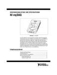
Analog Sensors Vernier myDAQ Adapter Order Code BT-MDAQ The Vernier myDAQ Adapter allows you to connect Vernier sensors to National Instruments' myDAQ interface. The adapter includes two connectors for Vernier analog sensors and one connector for Vernier digital sensors. A screw terminal and header pins provide access to myDAQ lines not used by the connectors. This includes the two analog output lines, three digital lines (including the digital lines with the frequency and pulse width modulation outputs), and +5 volt power. Power Vernier sensors require a 5 volt source. The myDAQ does have a +5 V power supply, but this supply sags when loaded, which may affect sensor readings. Therefore, the adapter uses myDAQ's +15 V power, and a DC to DC converter, to create a regulated +5 volt power source for the sensors. This power source is also routed to the screw terminal labeled 5 V. The available current from this regulated voltage is around 85 mA. Most Vernier sensors require less than 10 mA. However, there are a handful, like Motion Detector, Ethanol and Dissolved Oxygen, that have an average current draw around 50 mA (of special note is the old model Motion Detector (blue) that requires about 100 mA). If you are using several of these high-current sensors at the same time, then you will need to provide more current than what is available from the myDAQ. In this case you will need to connect an external power supply. The external power supply port on the Vernier myDAQ Adapter board is designed to be used with Vernier's LabQuest Power Supply (order code LQ-PS). You might also consider using the LQ-PS external power supply if you want to provide more current to the 5 V screw terminal. For example, if you are using the 5 V screw terminal to provide power to an external circuit, or to power a servo motor, then you would want to use the LQ-PS external power supply to increase the available current. The Vernier myDAQ Adapter includes connectors on the circuit board for connecting two Vernier analog sensors. The connectors for the analog sensors (CH1 and CH2) are located on the left side of the board. Examples of Vernier analog sensors are pH, temperature, force sensors, oxygen gas, and blood pressure. Vernier analog sensors require a 5 volt source and provide a 0–5 volt signal. The 0–5 volt signal comes from the sensor's SIG1 line. The figure above shows how the signal from Vernier sensors are wired to the myDAQ. The SIG1 and GND lines of CH1 are wired to myDAQ analog input lines AI0+ and AI0–, and the SIG1 and GND lines of CH2 are wired to myDAQ analog input lines AI1+ and AI1–. We have not wired the sensor connector's SIG2 line to the myDAQ. The SIG2 line is reserved for Vernier analog sensors that send a ±10 volt signal. Currently this only includes the Vernier simple voltage probe and 30V voltage probe. Therefore, these two sensors are not compatible with the myDAQ. To take voltage measurements you can use Vernier's differential voltage probe, which is a 0–5 volt sensor that sends the signal on the SIG1 line. Another option is to take voltage measurements using myDAQ's digital multimeter. Sensor lines VRES and ID are also not wired. These lines are used for automatically identifying sensors and reading stored calibration values from Vernier sensors with Vernier interfaces. This feature is not supported with the myDAQ. 2 Analog Sensor Calibration Digital Sensors All Vernier sensors are shipped with a User Manual. This manual is also posted on the Vernier web site. Refer to the sensor's User Manual to understand how the sensor is calibrated. Keep in mind that the User Manual is written assuming you are using a Vernier interface and Vernier Logger Pro software. However, information on how a sensor works and the default calibration equation will be useful. In most cases, Vernier sensors provide a 0 to 5 volt signal that can be converted to sensor units with a linear calibration. The default slope and intercept values for the linear equation are provided in the sensor's User Manual. For better results you should perform a two-point calibration on your sensor and calculate the slope and intercept. Do this by recording the raw voltage reading of the sensor using two known external reference values. Preferably, these points should be widely separated and be on either side of the intended readings you anticipate in your experiment. Your calibration is only as good as your knowledge of the reference values. Calibrating Vernier Temperature Probes There are a few sensors that do not have a linear calibration and require a more complicated calibration equation. Refer to the User Manual to better understand the calibration equation. Two of these sensors are the Stainless Steel Temperature Probe and the Surface Temperature Sensor. These sensors are electrically the same but packaged differently. Both use thermistors in series with a fixed resistor in a voltage divider situation. The voltage at the point between the fixed resistor and the thermistor is measured and used to determine temperature. The relationship between voltage and temperature is normally modeled with the Steinhart-Hart equation. In order to perform the Steinhart-Hart equation you will need to know the coefficients for the Vernier thermistor, the value of the fixed resistor, and the source voltage. The coefficients for Vernier thermistors are: K0 = 0.00102119, K1 = 0.000222468, and K2 = 1.33342E-7. The value of the fixed resistor is 15 k, and the source voltage is 5 volts. Consider measuring the source voltage for more accuracy in your equation (the source voltage can be measured from the screw terminal labeled 5 V). LabVIEW VIs for Analog Sensors Configure your LabVIEW program to read from AI0 if reading CH1 and AI1 if reading CH2. The myDAQ is designed to read the analog inputs in differential mode. Vernier sensors provide a signal that ranges from 0 to 5 volts. Therefore, configure your LabVIEW code to read in a similar input range. The 0–5 volt signal that you are reading is the raw voltage reading from the sensor. To convert this reading to proper sensor units you must apply a calibration equation. This is easy to do in LabVIEW using the math functions or inputting the calibration equation in the DAQ Assistant, for example. 3 The Vernier myDAQ Adapter includes one connector on the circuit board for connecting Vernier digital sensors. The connector for the digital sensors (DIG1) is located on the right side of the board. Examples of Vernier digital sensors are Motion Detector, Rotary Motion Sensor, Photogate, Drop Counter, Digital Control Unit (DCU), and Radiation Monitor. Vernier digital sensors require a 5 volt source and provide a signal that is either high (5 volts) or low (0 volts). The figure above shows how the Vernier digital sensor connector is wired to the myDAQ. To understand the wiring, you must understand the signal lines of Vernier sensors. Here is a table of how the various sensors use the four digital I/O lines of the digital sensor connector during operation. DIG1 Connector DIO3 DIO2 DIO1 DIO0 Photogate Block and Unblock Radiation Monitor Count Rotary Motion X4 Resolution Motion Detector CWCount CCWCount Init Echo 4 DCU Dig Out Dig Out Dig Out Dig Out Motion Detector LabVIEW VIs for Digital Sensors This section outlines some ways to use your myDAQ to take measurements with Vernier digital sensors. In order to write your VIs you must understand what lines the various digital sensors use and how these lines are connected to the myDAQ. This information is found in the Digital Sensors section. In addition, you need to know how the myDAQ digital lines and counter works. Digital lines DIO <0..7> can perform digital input and output, lines DIO <0..4> have counter/timer functionality. Photogate The Vernier Motion Detector's Init is on the connector's DIO1 line. This line is wired to myDAQ DIO2 and DIO6. To initialize the Motion Detector you must do two things; turn the line high to fire a sound wave from the gold foil of the ultrasonic transducer (using myDAQ line DIO6) and start two-edge separation timing (using myDAQ line DIO2). When the echo signal from this sound wave is picked up by the transducer the connector's DIO0 line goes high. This line is wired to myDAQ DIO1. Configure your myDAQ for the following: The Vernier Photogate signal comes on the connector's DIO0 line. This line is wired to myDAQ DIO0 and DIO1. The photogate signal is high (5 volts) when unblocked and low (0 volts) when blocked. Configure your myDAQ channels DIO0 or DIO1 in either of the following ways: DIO6 DIO0 DIO1 DIO2 Simple counting of blocked/unblocked states. Timing measurements (period and pulse width). Radiation Monitor The Vernier Radiation Monitor "count" signal comes on the connector's DIO0 line. This line is wired to myDAQ DIO0 and DIO1. However, when measuring radiation, you only require simple counting, which occurs on myDAQ channel DIO0. Configure your myDAQ for the following: DIO0 Simple counting. Digital Control Unit Rotary Motion The Vernier Rotary Motion sensor sends the counter-clockwise (CCW) signal on the connector's DIO0 line. This line is wired to myDAQ DIO0. The clockwise (CW) signal is sent on the DIO1 line. This line is wired to myDAQ DIO2. It is possible to use the myDAQ counter to measure both CCW and CW directions by configuring the angular encoder to measure in Two Pulse Counting mode. The Rotary Motion's X4 resolution comes on the connector's DIO3 line. This line is wired to myDAQ DIO5. Configure your myDAQ for the following: DIO0 DIO2 DIO5 DIO1 Digital output. Use this line to activate the sound wave. You may need to experiment with how long this line stays on and how much of a pause you provide between firing the sound waves. Start by turning this line high for about 40 milliseconds, with a 50 millisecond pause before turning it high again. Start signal for measuring two-edge separation. Note that DIO6 is wired directly to this input, so when the DIO6 line is turned high it will activate the sound wave and be detected as the first rising edge. Stop signal for measuring two-edge separation. This is the rising edge of the echo signal. The distance of the object being measured can be calculated using the two-edge separation measurement (the time from the rising edge of the Init signal to the rising edge of the Echo signal). The speed of sound can be used to determine the distance sound traveled in that time. This is twice the distance to the object. Quadrature encoder signal A. Quadrature encoder signal B. Digital output. Use this line to activate or de-activate 4x resolution. Keep line DIO5 off for low resolution (1°) and keep the line on for high resolution (0.25°). The Vernier Digital Control Unit (DCU) is a device that provides useful current for digital out lines. It is designed to make connecting and controlling small electronic components very quick and easy. Connecting the DCU to the adapter's digital channel allows access to myDAQ digital output lines that are not accessible from the adapter's screw terminal. To activate the various DCU output lines, configure the myDAQ for the following: DIO1 DIO2 DIO4 DIO5 Digital Output Digital Output Digital Output Digital Output Screw Terminals and Header Pins As shown in the schematic for the analog and digital connector, many of the myDAQ channels are used for reading Vernier sensors. However, we have provided access to the unused channels via a screw terminal connector and several header pins. Available channels on the screw terminal include AO0, AO1, DIO4, and GND. These lines are coming directly from the myDAQ, and you should consult the myDAQ User Manual to understand their capabilities. The screw terminal includes a 5 V channel. This line is coming from our power circuit, as explained in this manual's Power section. 5 6 Header Pins A series of eight header pins are located behind the screw terminal connector. These are the same outputs as the screw terminals, and in the same order. They provide a different way to connect your electronic devices, or as an easy way to monitor the outputs with a multimeter, for example. A series of three header pins are located at the front, right-side of the board. These pins include DIO3, GND, and 5 V. These pins are specifically useful for connecting a RC servo motor. These small, inexpensive servo motors require a pulse output on their signal line. The myDAQ DIO3 line is capable of providing the correct pulse output. In addition, these servos require a 5 volt power supply with ample current. This is not possible with the myDAQ, but it is possible by connecting the Vernier myDAQ Adapter to the LQ-PS external power supply. A series of two header pins are also in this location, providing one more myDAQ digital output line, line DIO7, and ground. Resources and Example VIs For up to date resources and web links for the myDAQ adapter, including sample VIs, go to www.vernier.com/products/interfaces/bt-mdaq Warranty Vernier warrants this product to be free from defects in materials and workmanship for a period of five years from the date of shipment to the customer. This warranty does not cover damage to the product caused by abuse or improper use. Vernier Software & Technology 13979 S. W. Millikan Way Beaverton, OR 97005-2886 Toll Free (888) 837-6437 (503) 277-2299 FAX (503) 277-2440 [email protected] www.vernier.com Rev. 1/17/2014 Logger Pro, Logger Lite, Vernier LabQuest, Vernier LabQuest 2,Vernier LabQuest Mini, Vernier LabPro, Go! Link, Vernier EasyLink and other marks shown are our trademarks or registered trademarks in the United States. National Instruments, NI, ni.com, and LabVIEW are trademarks of National Instruments Corporation. All other marks not owned by us that appear herein are the property of their respective owners, who may or may not be affiliated with, connected to, or sponsored by us. Printed on recycled paper. 7 8