1
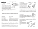
TD2M.TD3M
2 Phase Micro Stepping Motor Driver User’s Manual
※Scan with your
smart phone online!
TD2M/TD3M
2 Phase Micro Stepping Motor
Driver User‟s Manual
TD2M.TD3M-VN-V02E
TD2M.TD3M
2 Phase Micro Stepping Motor Driver User’s Manual
Contents
1. Product specs…………………………………………………….…..
2. Names and functions of driver part…………………………………
3. Potentiometer for adjusting motor current…………………………
4. Wiring diagram………………………………………………………..
5. Wiring & operation……………………………………………………
6. Dimension & installation……………………………………………..
1
2
4
5
6
8
TD2M.TD3M-VN-V02E
TD2M.TD3M
2 Phase Micro Stepping Motor Driver User’s Manual
Precautions
Precautions for using
1.Thank you for purchasing TROY products. Please read this user‟s manual thoroughly before installing
and operating the driver, and always keep the manual where it is readily available.
2. The products described in this manual has been designed and manufactured for use in industrial
machinery, and must not be used for any other purpose. We are not responsible for any damage
caused through failure to observe this warning.
3.Check that the motor, driver and any accessories are all present. If an accessory is missing or
damaged, contact the nearest our branches.
4.Never disassemble the motor and driver. Damage or performance impairment may result.
Disassembly voids all warranties.
Precautions for maintenance
Check the ambient environments, clean the system equipment to remove dust and tighten the screws
periodically. Also pay attention to the followings.
1. Contact us when repairs become necessary.
2. Since the temperature of the frame of the driver can rise high, be careful when conducting
maintenance work or inspection work
Precautions for warranty period
Within the period of one year after delivery of the system equipment, when failures occurring
from design error or fabrication error attributable to the manufacture side occur, we will be
repairing the failure free of charge within the reparable range or will replace with substitute.
(We cannot hold ourselves responsible for breakage and accidents occurring from your use beyond the
specified range described in this document.)
Precautions for disposal
When disposing of the driver and the motor, treat them as ordinary industrial waste.
TD2M.TD3M-VN-V02E
TD2M.TD3M 2 Phase Micro Stepping Motor Driver User’s Manual
1. Product specs
●Specs
Driver model
Drive current
Power input
Excitation mode
Signal output & input mode
CW pulse input
Input
signal
CCW pulse input
H.OFF input
Output
signal
TIMING output
Functions
Protection functions
Light display
TD2M
TD3M
0.1~2A/phase
0.52~3A/phase
DC24V~36V
DC24V~36V
Min : 3A
Min : 3.6A
Microstep with the resolution 200~3200 dpi
1.8°~0.1125°/Step
●Photo coupler input
●Open collector output
2 pulse:Clockwise rotation input;1 pulse:pulse input
2 pulse:Counterclockwise rotation input 1pulse:Rotation direction input
Excitation release input (Holding off)
The signal is output every time the excitation sequence returns to
the initial stage”0”
TIMING LED lit up continuous when the resolution is 200 dpi
Signal output every 2 pulse when the resolution is 400 dpi
Signal output every 4 pulse when the resolution is 800 dpi
Signal output every 8 pulse when the resolution is 1600 dpi
Signal output every 16 pulse when the resolution is 3200 dpi
●Automatic current cut back (ACD)
●Self-test (TEST)
●Overvoltage protection on the signal terminal (5~24V)
●Inverse power protection: auto disconnection in the case of
reversed voltage polarities
●Out of phase of the motor cable
●Wrong connection of the motor phase
●Motor short circuit protection
Power/TIMING
Dimension(mm)
90(L)X65(W)X32(H)
Weight
174g
Ambient temperature
0℃~40℃
●Driver
name and product number code
T
TROY Driver
D
2
Motor current
2 : 2A
3 : 3A
1
M
M : Micro step
TD2M.TD3M-VN-V02E
TD2M.TD3M 2 Phase Micro Stepping Motor Driver User’s Manual
2. Names and functions of driver parts
1
2
3
4
5
6
7
8
9
10
11
12
13
Front panel
No.
Display
Type
Name of the functions
Functions
1
POWER
LED
Power indicator
Lights when power is on
2
TIMING
LED
TIMING indicator
Lights when TIMING signal is output
Power positive pole input
External power positive pole
(+terminal)
(V+)connected to this terminal
Power ground input
External power negative
(-terminal)
pole(V-)connected to this terminal
3
DC24V/36V
I
2 Pulse:CW pulse
4
CW
I
signal input
1 Pulse:Pulse signal input
2 Pulse : CCW pulse
5
6
CCW
H.OFF
I
I
signal input
Notes
Clockwise rotation pulse input
Pulse input
DC24V~36V
L:0~0.5V
H:4~5V
Counterclockwise rotation input
Input
impedance
1 Pulse : Rotation
“L” level CW rotation,”H” level CCW
→220Ω
direction input
rotation
Input
Input the(L)level to released the
current
holding torque and motor shaft can
→Max.20 mA
Holding torque release
be rotated by hand
7
TIMING
O
Excitation timing output
8
RUN
SW
Motor run current switch
2
Outputs signals when the excitation
sequence is at STEP”0”
For adjusting the motor running
current
Default:A
TD2M.TD3M-VN-V02E
TD2M.TD3M
9
STOP
2 Phase Micro Stepping Motor Driver User’s Manual
VR
Motor stop current switch
For adjusting the current dropping
rate at motor standstill
Default:50%
※ The indication of type: LED : LED indicator, SW: Switch, VR: Variable resistor,
I: Input contact, O: Output contact
14
Left side of panel
No.
Display
Type
Name of the functions
Switch
OFF side
10
OFF/ACD
SW
Automatic current cutback
ACD side
Functions
Notes
After pulse input stop,
Default:ACD
motor current stay at the
※ACD
motor running
function can
After pulse input stop
prevent the
around 0.1 sec, motor
temperature
current decrease
rising
automatically and the
temperature will lower
down. The drop rate
adjusted by STOP-VR
TEST side
11
TEST/OFF
SW
Driver rotated in CW
Default:OFF
direction by 2pps.
Self test function stops
Self test
OFF side
and please flick to the
OFF side when motor
running
12
13
14
1P/2P
M1/M2/M3
MOTOR
SW
SW
O
1P
1 Pulse input
Default:2P
2P
2 Pulse input
000
200 dpi with current 70%
Default:
001
200 dpi with current 100%
1600dpi
010
400 dpi with current 70%
011
400 dpi with current 100%
100
800 dpi
101
1600 dpi
110
3200 dpi
111
HOLD.OFF
Pulse input mode
Resolution adjustment
Motor connector
Connecting the motor
※The indication of type:LED:LED indicator,SW:Switch,VR:Variable resistor, ︱:Input contact,O:Output contact
3
TD2M.TD3M-VN-V02E
TD2M.TD3M
2 Phase Micro Stepping Motor Driver User’s Manual
The front view of motor
The axis of motor
CCW
(Counterclockwise)
CW
(Clockwise)
3. Potentiometer for adjusting motor current
1.Adjusting the motor running current
a.Adjusting the motor running current by 『RUN』switch
TD2M : Adjusting range0.24A/phase~2A/phase
TD3M : Adjusting range0.52A/phase~3A/phase
b.The default current value setting at scale「A」
TD2M : Rated current is 1.28A/phase around 64% of rated current
TD3M : Rated current is 2.16A/phase around 64% of rated current
★Please note the driver RUN current value do not over the motor rated current value A/phase★
The dial settings and corresponding levels of motor operating current for TD2M/TD3M as below:
Scale
0
1
2
3
4
5
6
7
8
9
A
B
C
D
E
F
TD2M
Operating current(A/phase)
0.23
0.23
0.25
0.38
0.49
0.61
0.73
0.86
1
1.13
1.28
1.43
1.58
1.73
1.89
2
4
TD3M
Operating current(A/phase)
0.52
0.52
0.6
0.8
1
1.2
1.36
1.56
1.76
1.88
2.16
2.32
2.48
2.64
2.84
3
TD2M.TD3M-VN-V02E
TD2M.TD3M
2 Phase Micro Stepping Motor Driver User’s Manual
2. Adjusting the motor current at standstill by「STOP」switch
The switches sets the amount of reduction in motor current relative to the operating current at 10
different levels between 0~10.The motor current in the stopped state will be operating current
multiplied by the set cutback rate and the rate range is from 10%~65%.
The dial settings and corresponding levels of motor operating current as below:
Scale
Current cutback rate(%)
1
10
2
10
3
20
4
30
5
40
6
48
7
52
8
58
9
60
10
64
11
65
4. Wiring diagram
2 phase stepping motor
DC Power
External power
Control interface
CW input
CCW input
Excitation current
cut off
5
TD2M.TD3M-VN-V02E
TD2M.TD3M 2 Phase Micro Stepping Motor Driver User’s Manual
2 phase stepping motor
Motor wiring chart
internal wiring
Tamagawa
TROY
A phase
A phase
B phase
B phase
SANYO
DENKI
TS3103N40
ORIENTAL
A
Black
Orange
Black
Red
Black
COM
Yellow
White
Yellow
Black
Yellow
/A
Green
Blue
Green
Red/White
Green
B
Red
Red
Red
Green
Red
COM
White
Black
White
White
White
/B
Blue
Yellow
Blue
Green/White
Blue
※The different specifications of SANYO103-8□□series
has different wiring method, please contact to us
「[email protected]」
5. Wiring &Operation
5.1 Pulse DIR Input
Internal circuit
Controller
output
★Note: the signal input voltage range is 5V ~ 24V, it can be used without limiting resistor.
(1) 2 pulse input mode
The negative edge-triggered input is employed. The motor stays at „‟H‟‟ level when no pulse
signal input.
The pulse signal goes to CW terminal and the motor rotated 1 step in clockwise rotation.The
pulse signal goes to CCW terminal and the motor rotated 1 step in counterclockwise rotation.
(2) 1 pulse input mode
The negative edge-triggered input is employed. The motor stays at „‟H‟‟ level when no pulse
signal input. The pulse signal goes to CW terminal, while the operating rotation signal goes to
CCW terminal. CCW rotation in”L” level CW rotation in”H” level.
(3) Pulse voltage range: 4~5V for „‟H‟‟ level, 0~0.5V for „‟L‟‟ level.
(4) Pulse width>5μsec minimum, up/down time <2μsec maximum
6
TD2M.TD3M-VN-V02E
TD2M.TD3M
2 Phase Micro Stepping Motor Driver User’s Manual
5.2 H.OFF Input
Internal circuit
Controller
output
★Note: the signal input voltage range is 5V ~ 24V, it can be used without limiting resistor.
※When control signal H.OFF is “L” level, the motor current stop then motor‟s holding force release.
5.3 TIMING Output
★Note
Controller
input
Driver internal circuit
Please add proper external
resister(R) to keep
the current of circuit under 10mA
Vo
R =
RS
10mA
This timing signal is output to indicate when the motor excitation is in the initial stage(step “0” at
power up)The TIMING lamp is lit up continuously during the operation with high speed and
transistor is on.
TIMING lamp lit up continuously when 200 dpi
TIMING signal outputs when input every 2 pulse with 400 dpi
TIMING signal outputs when input every 4 pulse with 800 dpi
TIMING signal outputs when input every 8 pulse with 1600 dpi
TIMING signal outputs when input every 16 pulse with 3200 dpi
7
TD2M.TD3M-VN-V02E
TD2M.TD3M
2 Phase Micro Stepping Motor Driver User’s Manual
5.4 Protection Functions
Explanation of protection
Activation
Action
Inverse power protection
No power
Checking the positive and
negative level from the power
Out of phase of the
motor cable
Power lamp flicked
Checking is any out of phase
from the motor cable
Motor short circuit protection
Power lamp flicked
Checking is any short circuit
from motor cable
functions
Wrong connection of the
Checking the phase sequence
Power lamp flicked
motor phase
of motor cable
※When the power lamp blinking indicates the motor wiring has abnormal situation.
Please recheck the motor wiring is correct or not.
6. Dimension & installation
Driver dimension
Mounting bracket dimension
8
TD2M.TD3M-VN-V02E
TD2M.TD3M
●Driver
2 Phase Micro Stepping Motor Driver User’s Manual
installation mode
1.Horizontal installation
Mounting
Plate
Mounting
Plate
<Step 1>
<Step2>
Lock the installation seat onto the
mounting plate by using 2 screws
Fit the driver into the groove of
mounting plate. Mounted with 2
screws
2. Vertical installation
Method 1.
<Step 1>
<Step 2>
Remove the middle 2 screws
of driver. Vertically fit the driver
into the groove of the
mounting base.
Then re-mount the 2
removed screws
9
Lock the mounting
bracket on the
mounting plate by
using 4 screws
Mounting
Plate
TD2M.TD3M-VN-V02E
TD2M.TD3M
2 Phase Micro Stepping Motor Driver User’s Manual
Method 2.
<Step 1>
<Step 2>
Remove the middle 2 screws
of driver. Vertically fit the driver
into the groove of the
mounting base.
Then re-mount the 2
removed screws
Lock the mounting
bracket on the
mounting plate by
using 2 screws
Mounting
Plate
TD2M.TD3M-VN-V02E
10
TD2M.TD3M
2 Phase Micro Stepping Motor Driver User’s Manual
*For environment protection, paper saving and resources preservation, please download the user‟s manual directly from TROY website:
http:// www.troy.com.tw
※ Environmental Responsibility
● TROY is always committed to environment protection. All packaging material is recyclable and reusable.
● If disposing of used product, please recycle by type as per waste disposal procedures.
----------Protect the green earth with your care and commitment---------※The product is subject to design modification for performance improvement without prior notice. For more details, please contact with your
local seller.
TROY ENTERPRISE CO., LTD
Professional manufacturer
Website:www.troy.com.tw
E-mail: [email protected]
TEL:+886-2-2999-4500
Anlagentechn ik G mb H
ISO14001
Certificate No.: 09 104 9351
COPYRIGHT © 2011 TROY ENTERPRISE CO., LTD.
TD2M.TD3M-VN-V02E