1
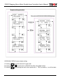
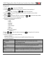
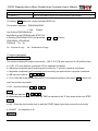
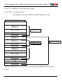
P602C Stepping Servo Motor Double Axes Controller User’s Manual
P602C
Stepping Servo Motor Double
Axes Controller User’s Manual
Made by TROY Enterprise Co., Ltd
Anlagentechn ik G mb H
ISO14001
Certificate No.: 09 104 9351
Environment Responsibility
●
TROY is always committed to environment protection. All packaging material is
●
recyclable and reusable.
If disposing of used product, please recycle by type as per waste disposal procedures.
---------------Protect the green earth with your care and commitment---------------
※The product is subject to design modification for performance improvement without prior
notice. For more details please contact with your local seller.
P602C-PI-V02E
P602C Stepping Servo Motor Double Axes Controller User’s Manual
Precautions
Precautions for using
1.Thank you for purchasing TROY products. Please read this user’s manual thoroughly before
installing and operating the driver, and always keep the manual where it is readily available.
2. The products described in this manual has been designed and manufactured for use in
industrial machinery, and must not be used for any other purpose. We are not responsible for
any damage caused through failure to observe this warning.
3.Check that the motor, driver and any accessories are all present. If an accessory is missing or
damaged, contact the nearest our branches.
4.Never disassemble the motor and driver. Damage or performance impairment may result.
Disassembly voids all warranties.
Precautions for maintenance
Check the ambient environments, clean the system equipment to remove dust and tighten the
screws periodically. Also pay attention to the followings.
1. Contact us when repairs become necessary.
2. Since the temperature of the frame of the driver can rise high, be careful when conducting
maintenance work or inspection work.
Precautions for warranty period
Within the period of one year after delivery of the system equipment, when failures occurring
from design error or fabrication error attributable to the manufacture side occur, we will be
repairing the failure free of charge within the reparable range or will replace with substitute.
(We cannot hold ourselves responsible for breakage and accidents occurring from your use
beyond the specified range described in this document.)
Precautions for disposal
When disposing of the driver and the motor, treat them as ordinary industrial waste.
P602C-PI-V02E
P602C Stepping Servo Motor Double Axes Controller User’s Manual
Contents
1.Name of controller parts…………………………………………
1
2.20 pins connector signal………………………………………… 1
3.10 pins connector signal………………………………………… 2
4.6 pins tip switch…………………………………………………… 2
5.5 pins tip switch…………………………………………………… 3
6.Specs……………………………………………………………… 3
7.Internal output circuit……………………………………………
4
8.Internal input circuit……………………………………………… 5
9.Operation data setting…………………………………………… 5
10.External operation control……………………………………… 11
11.Test mode………………………………………………………… 14
12.Dimension………………………………………………………… 15
13.P602C mounting diagram……………………………………… 15
14.Wiring……………………………………………………………… 16
※For any operational or technical question with the product, please contact us for professional
service「0800-450-168」during our business hours.
P602C-PI-V02E
P602C Stepping Servo Motor Double Axes Controller User’s Manual
1.Name of controller parts
「10/20 PIN connector」
「5/6 PIN tip switch」
LCD monitor
SXPULSE=+0000000
YPULSE=+0000000
Power indicator
Slide switch
Home position
indicator
BUSY indicator
2.20 pins connector signal
Pin No.
1
2
3
4
Input/Output
Input
Input
Input
Input
Name
0V
+24V
START
R/S
5
Input
STOP
6
7
8
9
10
11
Output
Output
Input
Input
Input
Input
BUSY
READY
SEL1
SEL2
SEL3
S/L
12
Input
BL
13
Input
BHL
14
15
16
Input
Input
Input
ORG
FL
FHL
「Button」
17
Output
CW+
18
Output
CW19
Output
CCW+
20
Output
CWPlease do not turn on the power when installed the
20 pins connector(Do not work under live!)
Function
Power input (0V)
Power input (+24V)
Start signal
L→SCAN (Continuous operation)
H→RUN (Positioning operation)
Emergency stop L→Operation stop
H→Operation permissible
Output signal during pulse generated (L output)
Output signal during pulse ended (H→L→H)
Positioning option/Continuous operation
Positioning option/Continuous operation
Positioning option
H→S curve acceleration
L→ Linear acceleration
Detection signal input:Counterclockwise rotation
limitation
Detection signal input:Counterclockwise rotation
deceleration then stop
Detection signal input:Mechanical home position
Detection signal input:Clockwise rotation limitation
Detection signal input:Clockwise rotation deceleration
then stop
CW pulse output:Connect with driver CW+
CW pulse output:Connect with driver CWCCW pulse output:Connect with driver CCW+
CCW pulse output:Connect with driver CCWL:Terminal connected with 0V
H:Terminal OPEN
1
P602C-PI-V02E
P602C Stepping Servo Motor Double Axes Controller User’s Manual
3.10 pins connector signal
1.
Input
S/L
H→S shape line acceleration
Input
YBL
Detection signal input:Y axis counterclockwise rotation
limitation
Input
YBHL
Detection signal input:Y axis counterclockwise rotation
deceleration then stop
Input
YORG
Detection signal input:Y axis mechanical home position
Input
YFHL
Detection signal input:Y axis clockwise rotation deceleration
then stop
6.
Input
7.
Output
YFL
YCW+
Detection signal input:Y axis clockwise rotation limitation
Y axis CW pulse output:Connecting driver CW+
8.
Output
YCW-
Y axis CW pulse output:Connecting driver CW-
9.
Output
YCCW+
Y axis CCW pulse output:Connecting driver CCW+
10.
Output
YCCW-
Y axis CCW pulse output:Connecting driver CCW-
2.
3.
4.
5.
Please do not turn on the power when
installed the 20 pins connector(Do not
L→Liner acceleration
L:Terminal connected with 0V
H:Terminal OPEN
work under live!)
4.6 pins tip switch
Pin
No.
Name
1
TEST
TEST MODE
2
XFHL
Detection mode:X axis clockwise
rotation deceleration then stop
3
XFL
Detection mode:X axis clockwise
rotation limitation
4
XORG
Detection mode:X axis mechanical
home position
5
XBHL
Detection mode:X axis
counterclockwise rotation deceleration
then stop
6
XBL
Function
Description
OFF:Operation mode
ON:Test mode
1.OFF:Normal close detection mode
2.ON:Normal open detection mode
3.If there is no need 2~6 functions
Please switch the tip switch to the ON
side.
Detection mode:X axis
counterclockwise limitation
2
P602C-PI-V02E
P602C Stepping Servo Motor Double Axes Controller User’s Manual
5.5 pins tip switch
Pin
No.
Name
Function
1
YFL
Detection mode:Y axis clockwise rotation
2
3
4
5
Description
OFF:Operation mode
ON:Test mode
Detection mode: Y axis clockwise rotation 1.OFF:Normal close detection
deceleration then stop
mode
Detection mode:Y axis mechanical home 2.ON:Normal open detection mode
YORG
3.If there is no need 2~6 functions
position
Detection mode:Y axis counterclockwise Please switch the tip switch to the
YBHL
ON side.
rotation deceleration then stop
XFHL
YBL
Y axis counterclockwise rotation limitation
6.Specs
Positioning data
Positioning
control
Control mode
Operation mode
Input signal
Output signal
Power input
Ambient
temperature
8 sets programs and saved by EEPROM
Each function capacity as below:
POSITIONING 29Bytes
TIME
3Bytes
INPUT
2Bytes
OUTPUT
2Bytes
REPEAT
3Bytes
END REAPEAT 1Bytes
CALL
2Bytes
RETURN
1Bytes
Per programs:9999999 PULSE
Operation pulse speed:35~59995 PPS
Start pulse speed:35~9995 PPS
Acceleration/deceleration time:1~9999 ms
External control mode (RUN MODE)
Data input mode (EDIT MODE)
Test mode (TEST MODE)
Positioning operation (INDEX)
Mechanical zero return mode (HOME)
Continuous operation (SCAN)
DC 24 V photocoupler input, input impendence 4.7KΩ
DC 24 V photocoupler ombined with transistor output,output current 25mA
DC 24 V photocoupler combined with transistor output,output current 25mA
DC 24V/100 mA
0℃~+40℃
3
P602C-PI-V02E
P602C Stepping Servo Motor Double Axes Controller User’s Manual
7.Internal output circuit
4
P602C-PI-V02E
P602C Stepping Servo Motor Double Axes Controller User’s Manual
8.Internal input circuit
9.Operation data setting
Before data setting,please switch the slide switch to the EDIT
a.Intialize(Default value)
The controller has defaulted before shipping
After power OFF,switch the slide switch to the EDIT then press the button「ENT」and turn the
power ON.
The LED indicated “*DATA-initial*” Please wait……then let the button「EDIT」off, all data
initialized and enter into the (EDIT)mode
Initialize data as below:
Common using data
Vs(Initial speed)=130 pps
Tacc/dec(Acceleration/deceleration time)=30 ms
ORG VR(Zero point end speed)=-1030 pps(+Clockwise rotation to the zero point,
-Counterclockwise rotation to the zero point)
Searching the zero point Setting(ORG motion set)
*ORG motion*
---YES--*YES:Back to the zero point under SCAN mode
*NO:Position indicats “0000000”and without back to the zero point under SCAN mode
5
P602C-PI-V02E
P602C Stepping Servo Motor Double Axes Controller User’s Manual
b.「EDIT」procedures
※Description of each button
► :1.X axis clockwise rotation「TEST-SCAN mode/TEACH mode」
2.Cursor move to the right「EDIT mode」
◄ :1.X axis counterclockwise「TEST-SCAN mode」
2. Cursor move to the left「EDIT mode」
SEL:1.Cursor switch from X to Y axis or from Y to X axis「Value editing」
2.Functions switching「ORIGINAL DATA of EDIT mode
Program edit」
3.Data switching 「IN
IN-OUT and OUT
OUT-NOT of EDIT mode」
4.Finish edit
ENT:Entering/Executing/Confirming「The functions indicated in the monitor」
▲ :1.Y axis clockwise rotation 「TEST-SCAN mode」
2.Increasing the value indicated in the monitor or modified the content
3.Upward to「TEST-SCAN mode」
▼ :1.Y axis counterclockwise rotation 「TEST-SCAN mode」
2.Decreasing the value indicated in the monitor or modified the content
3.Downward「TEST-SCAN mode or EDIT mode」
SEL + ◄ : Switching to modified the TEACH data「EDIT mode」
6
P602C-PI-V02E
P602C Stepping Servo Motor Double Axes Controller User’s Manual
Program editing procedure
Zero point and common data entering steps
※ORIGINAL DATA(Common data) setting
1.Pressing “SEL “ to switch with the Program edit
2.Pressing “▲ “or “▼ “ to select the Vs,ORG,VR,Acc/Dec time,ORG motion
3.Pressing” ENT” and entering the option then repeat the b.「EDIT procedure」to edit the data
7
P602C-PI-V02E
P602C Stepping Servo Motor Double Axes Controller User’s Manual
※Program edit
1. Pressing “▲ “or “▼ “ to select the 6 PROGRAM
2. Pressing” ENT” and entering the option then indicated the “Have data!Clear ?”
1.KEEP 2.CLEAR(Pressing the ◄
or ►
to select the keep/clear)
3. Pressing” ENT” entering the PROGRAM and the monitor indicated the step numbers
(STEP:XX) for input
4. Pressing” ENT” entering the(STEP:XX)or pressing the “▲ “or “▼ “ to select the step numbers
which edited already and do the following functions
a.> Entering the new step numbers(STEP:XX)
Indicates1.POSITIONING
2.TIME
3.INPUT
4.OUTPUT
5.REPEAT
6.END REPEAT
7.CALL
8.RETURN
*PROGRAM CONNECT
---< BACK >--Pressing “▲ “or “▼ “ to select the option and pressing ” ENT” entering then edit the data as
b.「EDIT procedure」
b.>Entering the edited step numbers (STEP:XX)
Indicates” STEP:XX”
View indicates:Glance/Ins indicats:Insert a step/Del indicates:Delete a step
c.>Function description
Name
Description
POSITIONING
Setting motor operation data:Vs,VR,Acc/Dec time PULSE
TIME
TIMER setting(Unit:10ms)
INPUT
Input START/START-NOT signal then execute the next step(STEP)
OUTPUT
Execute this step and output the READY/READT-NOT signal
REPEAT
Execute the times of the LOOP (END REPEAT/REPEAT is a set)
END REPEAT
It is the end of LOOP (END REPEAT/REPEAT is a set)
CALL
Jumping to the XX step and execute it (CALL/RETURN is a set)
RETURN
It is the end of CALL (Next step before back to the CALL)
PROGRAM CONNECT
The connection of edit the program:Finish this set then execute the
8
P602C-PI-V02E
P602C Stepping Servo Motor Double Axes Controller User’s Manual
other set
---< BACK >---
Back to the status (STEP:XX) before select the function
5.Pressing “SEL “when the monitor indicated STEP:XX
The monitor indicates:-PROGRAM END1.Yes!
2.Back!
Yes:Exit the PROGRAM edit
Back:Back to the PRORAM edit (STEP:XX)
6.Entering PROGRAM COPY and pressing ◄
PROGRAM→PROGRAM
FROM Xs TO Xd
Xs:Source of copy
or ►
to select
Xd:Destination of copy
7.Function description
PULSE of POSITIONING
The monitor indicated 3 kinds of input mode:1.KE 2.TH 3.PS after input the Vs,VR,Acc/Dec time
a.>1.KE. 2.TH are absolute coordinate,3.PS is opposite coordinate
b.>Absolute coordinate type:Positioning point moved by “0” which in opposite coordinate
c.>Opposite coordinate type:Positioning point moved by pre-point which in opposite coordinate
d.>KE:Input the data as “▲ ““▼ “"◄ “”► “
e.>TH:As SCAN mode moved the position to the expected position then press ” ENT” which can
input the position at present.
f.>PS:Input the data as “▲ ““▼ “"◄ “”► “
TIME
a.> Input the data as “▲ ““▼ “"◄ “”► “
b.>Executing this function has to wait the TIME countdown to the “0” then execute the next STEP
INPUT
a.> IN:Executing this function has to wait the START signal input then execute the next step
b.>IN-NOT:It is opposite to IN
OUTPUT
9
P602C-PI-V02E
P602C Stepping Servo Motor Double Axes Controller User’s Manual
a.>OUT:Pin 7(READY) of 20 PIN will output L signal
b.>OUT-NOT:It is opposite to OUT
Executing this function Pin 7(READY) of 20PIN will back to H level
REPEAT-END REPEAT description
:
REPEAT=5
TIME=1000 ms
Repeat 5 times
POSITIONING
END REPEAT
REPEAT=10
REPEAT=8
Repeat 8
3 times
Repeat 10 times
POSITIONING
END REPEAT
REPEAT=3
OUT
TIME=500 ms
OUT-NOT
END REPEAT
IN
TIME
END REPEAT
※REPEAT-END REPEAT is a set and it can not insert the other REPEAT before this loop
finished
10
P602C-PI-V02E
P602C Stepping Servo Motor Double Axes Controller User’s Manual
CALL-RETURN description
:
STEP:13
OUT
STEP:14
TIME=1000ms
STEP:15
OUT-NOT
STEP:16
RETURN
:
STEP:30
CALL STEP:13
STEP:31
POSITIONING
:
:
STEP:10
CALL STEP:20
STEP:11
OUT-NOT
:
STEP:20
POSITIONING
STEP:21
TIME=1000 ms
STEP:22
OUT
STEP:23
RETURN
:
11
P602C-PI-V02E
P602C Stepping Servo Motor Double Axes Controller User’s Manual
10.External operation control
a.Switching the slide switch to the RUN and control signal input via 20 pins/10 pins connector
b.Continuous operation
Step1.:Pin No.4(R/S) of 20 PINS connected o the 0V→SCAN MODE
Step2.:Selecting the liner acceleration or S curve line acceleration
Pin No.1(L/S) of 10 PINS connected to the 0V:Liner acceleration
No connection:S curve line acceleration
Step3.:Pin No.8(SEL1) of 20 PINS connected to the 0V:X axis continuous clockwise rotation
Pin No.9(SEL2) of 20 PINS connected to the 0V:X axis continuous counterclockwise
rotation
Pin No.10(SEL1) of 20 PINS connected to the 0V:Y axis continuous clockwise rotation
Pin No.11(SEL2) connected to the 0V:Y axis continuous counterclockwise rotation
No connection of each pin:Stop operation
c.Zero return
Step1.:Pin No.4 (S/R)of 20 PINS connected to the 0V→SCAN MODE
Step2.:Selecting the liner acceleration or S curve line acceleration
Pin No.1(L/S) of 10 PINS connected to the 0V:Liner acceleration
No connection:S curve line acceleration
Step3.:Pin No.3(START) of 20 PINS connected to the 0V:Execute the zero return
Pin No.5(STOP) of 20 PINS connected to the 0V:Emergency stop
12
P602C-PI-V02E
P602C Stepping Servo Motor Double Axes Controller User’s Manual
Counterclockwise rotation to the zero
Clockwise rotation to zero
Zero return procedure:
Input START command (X/Y axis start at the same time)→X or Y axis return to the zero and
stop→Both of X/Y axis stop→X axis final zero return→Y axis final zero return→Zero return
finished
d.Positioning operation
Step1.:Pin No.4(S/R) no connection→RUN MODE
Step2.:Selecting liner acceleration or S curve line acceleration
Pin No.11(L/S) connected to the 0V:Line acceleration
No connection:S curve line acceleration
Step3.:Selecting one of 1~8 set programs
13
P602C-PI-V02E
P602C Stepping Servo Motor Double Axes Controller User’s Manual
SEL1
SEL2
SEL3
PROGRAM 1
No connection
No connection
No connection
PROGRAM 2
L(0V)
No connection
No connection
PROGRAM 3
No connection
L(0V)
No connection
PROGRAM 4
L(0V)
L(0V)
No connection
PROGRAM 5
No connection
No connection
L(0V)
PROGRAM 6
L(0V)
No connection
L(0V)
PROGRAM 7
No connection
L(0V)
L(0V)
PROGRAM 8
L(0V)
L(0V)
L(0V)
Step4.:Pin No.3(START) connected to the 0V:Execute the selected program
Pin No.5(STOP) connected to the 0V:Emergency stop
◆P602C each set can edit max 80 STEPS
◆Executing mode is “Step by Step continuously”
STEP01→STEP02→STEP03→…………END
◆When meet the REPEAT ………..END REPEAT,it will repeat the STEP between the REPEAT
and END REPEAT
◆When meet the jumped STEP from CALL……RETURN during execution until meet the
RETURN and back to the next STEP before CALL
e.Emergency stop
Pin No.5 (STOP) of 20 PINS connected to the 0V and motor stops operation at Continuous
operation(SCAN MODE)、Zero return or Positioning operation(RUN MODE)
f.BUSY
When operation pulse outputs the Pins No.6(BUSY) of 20 PINS is Low outputs and the BUSY
indicator(Red) will lit up until operation pulse stopped output,Pin No.6(BUSY) changed to
Hi,the BUSY indicator(Red) goes off
g.READY
When executed the OUT order of OUTPUT function,the Pin No.7 (READY) of 20 PINS connector
outputs L signal.If executed the OUT-NOT order function,the Pin No.7 (READY) of 20 PINS
connector back to H level
14
P602C-PI-V02E
P602C Stepping Servo Motor Double Axes Controller User’s Manual
11.TEST mode
a.Functions
Executing the Continuous operation、Zero return or Positioning operation function on the panel
b.Setting
Switching the slide switch to the RUN and switch the first PIN(6 PIN tip switch) to the ON
c.Execution
< TEST MODE >
When the monitor indicated
Origin
Search ?
It indicated Zero return waiting for execute and pressed the following buttons
‧Pressing ▲ :Forward to searching the other operation function as below:
Search HOME → SCAN → PROGRAM 1 → PROGRAM 2 →……→ PROGRAM 8 → SCAN →
Search HOME
‧Pressing ▼ :Backward to searching the other operation function as below:
Search HOME → SCAN → PROGRAM 8 → PROGRAM 7→......→PROGRAM 1 → Search
HOME
‧Pressing ENT:Executing the function which indicated in the monitor
Such as Search HOME → Executing the Zero ruturn
PROGRAM 1 → Executing the first set of operation pulse outputs
SCAN
→ Entering the continuous operation(SCAN MODE)
Pressing ► :X axis clockwise rotation(CW)
◄ :Y axis counterclockwise rotation(CCW)
▲ :Y axis clockwise rotation(CW)
▼ :Y axis counterclockwise rotation(CCW)
▼ :Exit the SCAN mode
‧Acceleration/Deceleration of pulse output in the TEST MODE which is S curve line
acceleration/deceleration and can not set via external
d.Exit the TEST MODE
Switching the first PIN(6 PIN tip switch) to OFF
15
P602C-PI-V02E
P602C Stepping Servo Motor Double Axes Controller User’s Manual
12.Dimension
13.P602C mounting diagram
Unit:mm
16
P602C-PI-V02E
P602C Stepping Servo Motor Double Axes Controller User’s Manual
14.Wiring
外部控制器
External
controller
COM
DC24V POWER
電源
+
-
20極連接器
20 pins connector
0V
1
+24V
2
START
3
R/S
4
STOP
5
Y-TABLE
BUSY
6
READY
X-TABLE
7
SEL1
8
SEL2
9
SEL3
10
XX軸馬達驅動器
axis motor driver
SEL4
11
XBL
12
XBHL
13
XORG
14
XFHL
15
XFL
16
XCW+
17
XCW18
XCCW+
19
XCCW20
+
+
-
CW
CCW
10 pins
connector
10極連接器
S/L
1
YBL
2
YY軸馬達驅動器
axis motor driver
YBHL
3
YORG
4
YFHL
5
YFL
6
YCW+
7
YCW-
8
YCCW+
9
YCCW10
17
+
+
-
CW
CCW
P602C-PI-V02E
P602C Stepping Servo Motor Double Axes Controller User’s Manual
*For environment protection, paper saving and resources preservation, please download the
user’s manual directly from SUNHOLY website:http:// www.sunholy.com.tw
Our constant aim:Demand for professionalism
Our belief:
Commitment to every detail
Our innovation: Introduction of cutting-edge equipments
Our pride:
Pursuit of superior products
We are confident that each SUNHOLY products bears tests
For we are highly motivated!
Complete SUNHOLY service system
We offer our customers a complete service package:
♁『0800-450-168 technical hotline service』
♁『Periodical motor E-newspaper』
♁『Motor selection and calculation service』
♁『Professional on site service』
♁『On-site motor technical seminar service』
♁『Total motor solution& after sales service』
Ready for request!.
SUNHOLY TRADING CO., LTD
Professional agency
3F,No78.,Sec2,Chang An E.RD. Taipei, Taiwan.
TEL:+886-2-2516-6060
FAX:+886-2-2508-0323
http://www.sunholy.com.tw
E-mail:[email protected]
P602C-PI-V02E