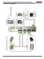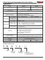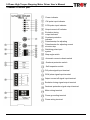
1
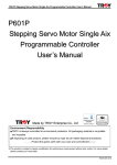
5-Phase High Torque Stepping Motor Driver User’s Manual
TR Series
5-Phase High Torque Stepping
Motor Driver User ’s Manual
Anlagentechn ik G mb H
Made by TROY Enterprise Co., Ltd
ISO14001
Certificate No.: 09 104 9351
Environment Responsibility
●TROY
is always committed to environment protection. All packaging material is recyclable
and reusable
●If disposing of used product, please recycle by type as per waste disposal procedures.
----------Protect the green earth with your care and commitment-------※The product is subject to design modification for performance improvement without prior notice. For more details
please contact your local seller.
TR514-X-QP-V08E
5-Phase High Torque Stepping Motor Driver User’s Manual
Precautions
Precautions for using
1.Thank you for purchasing TROY products. Please read this user’s manual thoroughly before
installing and operating the driver, and always keep the manual where it is readily available.
2. The products described in this manual has been designed and manufactured for use in industrial
machinery, and must not be used for any other purpose. We are not responsible for any damage
caused through failure to observe this warning.
3.Check that the motor, driver and any accessories are all present. If an accessory is missing or
damaged, contact the nearest our branches.
4.Never disassemble the motor and driver. Damage or performance impairment may result.
Disassembly voids all warranties.
Precautions for maintenance
Check the ambient environments, clean the system equipment to remove dust and tighten the
screws periodically. Also pay attention to the followings.
1. Contact us when repairs become necessary.
2. Since the temperature of the frame of the driver can rise high, be careful when conducting
maintenance work or inspection work.
Precautions for warranty period
Within the period of one year after delivery of the system equipment, when failures occurring from
design error or fabrication error attributable to the manufacture side occur, we will be repairing the
failure free of charge within the reparable range or will replace with substitute.
(We cannot hold ourselves responsible for breakage and accidents occurring from your use beyond
the specified range described in this document.)
Precautions for disposal
When disposing of the driver and the motor, treat them as ordinary industrial waste.
TR514-X-QP-V08E
5-Phase High Torque Stepping Motor Driver User’s Manual
CONTENTS
1.Specification………………………………………………………………. 1
2.Name of driver part………………………………………………………. 2
3.Current adjustment switch and operating methods……………….. 3
4.Connecting diagrams……………………………………………………. 6
5.Example of connecting diagrams and operating methods……….. 7
6.Dimensions and installations………………………………………….. 9
7. Diagrams and mounting……………………………………………………... 11
※For any operational or technical question with the product, please contact us for professional service「0800-450-168」
during our business hours.
TR514-X-QP-V08E
5-Phase High Torque Stepping Motor Driver User’s Manual
1. System Configuration
1
TR514-X-QK-V08E
5-Phase High Torque Stepping Motor Driver User’s Manual
2.Specifications
●
Specifications
Model
Input power
Drive current
TR514-1
AC100-115V±15% 5A
TR514-2
AC200-230V±10% 3A
50Hz/60Hz
50Hz/60Hz
1.4A/Phase
Full step:0.72∘4-Phase Excitation
Half step:0.36∘4-5-Phase Excitation (Convertible)
Excitation mode
●Photo
Signal input/output
CW Pulse input
Input signal CCW Pulse input
H.OFF input
coupler input interface
●Transistor open collector output interface
2 pulse:Clockwise input.
1 pulse:Pulse input
2 pulse:Counterclockwise input. 1 pulse:Rotation direction
input
Holding OFF input
TIMING output
Excitation phase origin output
Full step:10 signals output every 10 pulses
Half step:20 signals output every 20 pulses
O.HEAT output
The signal is output when the internal heat sink temperature
exceeds above 80℃
Output signal
Step angle switch (F/H)
●Automatic current off when overheat
●Pulse input mode switch (1P/2P)
●Automatic current cutback(ACD)
●Self test (TEST)
Overheat protection:The signal is output when the internal
temperature of the driver rises above 80℃,motor stop running
●
Functions
Protect function
Display (LED)
POWER, CW, CCW, H.OFF, TIMING, O.H.
115(L)×42(W)×200(H) mm
Dimension
Weight
939g
958g
0℃~40℃
Ambient temperature
●
Product number code:
T R
Driver
5
Motor type
5-Phase
1
4 - □
Drive current
1.4A/Phase
2
Input power
1:AC100-115V±15%
2:AC200-230±10%
TR514-X-QK-V08E
5-Phase High Torque Stepping Motor Driver User’s Manual
3.Names of driver part
Power indicator
-1
CW pulse input indicator
CCW pulse input indicator
Output current off indicator
Excitation timing
output indicator
Overheat protection
indicator
Potentiometer for adjusting
motor operating current
Potentiometer for adjusting current
at motor stop
Switching pulse input
system
Step angle switch
Automatic current cutback switch
Overheat protection switch
Self-inspection switch
CW pulse signal input terminal
CCW pulse signal input terminal
Output current off signal input terminal
Excitation timing signal output terminal
Overheat protection signal output terminal
Motor wiring terminal
Power grounding terminal
Power wiring terminal
3
TR514-X-QK-V08E
5-Phase High Torque Stepping Motor Driver User’s Manual
Code
Name of the
panel
Type
Name of function
1
POWER
LED
Power indicator
2
CW
LED
CW pulse input indicator
3
CCW
LED
CCW pulse input indicator
4
H.OFF
LED
Holding OFF indicator
5
TIMING
LED
Excitation phase origin output
indicator
6
O.H.
LED
Overheat protection indicator
7
RUN
SW
Motor run current potentiometer
8
STOP
SW
Motor stop current potentiometer
9
1P/2P
SW
Pulse input
Function
10
H/F
SW
1-pulse input
2P side
2-pulse input
Step angle switch
H side
OFF side
11
OFF/ACD
SW
Auto current cutback
ACD side
12
OFF/O.H.
SW
Overheat
protection switch
TEST/OFF
SW
CW
I
ACD
side
Overheat protection functioned
Self inspection switch
2 pulse:CW pulse signal input
1 pulse:Rotation direction control
2 pulse:Input CCW pulse signal
15
CCW
After stop inputting pulse almost
2secs, the current
Overheat protection is no function
OFF side
14
Full step operation,0.72°/step,
every 500 pulses turn around
Half step operation,0.36°/step,
every 1000 pulses turn around
After stop inputting pulse, the
current keeps at the value of
motor running
OFF
side
TEST side
13
LED lamp turns on upon power
input
When motor rotated clockwise the
LED lit up
When motor rotated
counterclockwise the LED lit up
When motor Holding OFF input
the LED lit up
Full step:LED lamp turns on
every 10 pulses
Half step:LED lamp turns on
every 20 pulses
LED lamp continuously on during
high speed operation.
Signal is output when the heat
sink temperature of the driver
rises above 80℃
Default:‘’A’’
Adjust the motor running current
Adjust the rate of motor current
Default:‘’6’’
down at standstill
1P side
F side
I
1 pulse:Rotation direction control
16
H.OFF
I
Holding off
17
TIMING
O
Excitation timing output signal
4
Remarks
Default:‘’2P’’
Default:‘’H’’
Default ‘’ACD’’
*ACD
recommended
to mitigate
temp rise of
motor/driver
Default:
’’O.H’’
The driver rotates CW at the
speed of 3pps
Stop self inspection immediately,
please set it on OFF side while
operation normally
Input clockwise pulse signal via
this terminal
Input pulse signal via this terminal
L:0~0.5V
Input counterclockwise pulse
H:4~5V
signal via this terminal
Input
‘’L’’ level clockwise rotation
impedance:
‘’H’’ level counterclockwise
200Ω
rotation
Input potential (L) holding off, it
Input current:
makes motor no excitation, and Below 20mA
the axis can be rotated freely by
hand
When full step, signal output
every 10 pulses
BelowDC24V
When half step, signal output
Below 10mA
every 20 pulses
TR514-X-QK-V08E
5-Phase High Torque Stepping Motor Driver User’s Manual
18
O.H.
O
Overheat protection signal output
terminal
19
MOTOR
O
Motor wiring
20
F.G.
I
Machine case ground terminal
21
TR514-1
AC100-115V
TR514-2
AC200-230V
I
Power input terminal
Signal is output when the heat
sink temperature of the driver
rises above 80℃,at the same
time the current output to motor is
lower to 0,motor at standstill
It’s use to connect the motor to
driver
Please do the shortest distance
connect with system ground wire
directly, or connect to the machine
case directly
Connect power voltage
AC100-115V±15% 5A 50Hz/60Hz
Connection power voltage
AC200-230V±10% 3A 50Hz/60Hz
※Type description:LED→LED lamp、SW→Switch、VR→Adjustable resistor、I→Input、O→Output
The front view of motor
The axis of motor
CW
(Clockwise)
CCW
(Counterclockwise)
5
TR514-X-QK-V08E
5-Phase High Torque Stepping Motor Driver User’s Manual
4.Current adjustment switch operating methods
(1) Adjusting the motor running current
a. Adjusts the motor current with 「RUN」potentiometer. The adjusting range is 0.45A/phase~
1.4A/phase
b. The current is defaulted at scale 「A」, the current is 1.07A/phase, approximately
current 75%
(2) Adjusting the current at motor standstill
a. Using the 「STOP」potentiometer to adjust the current during the motor at standstill. The
adjusting range is 23%~100%
b. The current is defaulted at scale「6」. Rate of current drop is 54% (Regard setting current value
of 「RUN」as the standard)
Run current (A/phase)
Drop rate of current (%)
TR514-1/TR514-2
TR514-1/TR514-2
0
0.45
23
1
0.47
29
2
0.54
34
3
0.60
39
4
0.66
44
5
0.73
49
6
0.79
54
7
0.85
59
8
0.93
65
9
1.00
70
A
1.07
75
B
1.14
80
C
1.20
85
D
1.27
90
E
1.34
95
F
1.40
100
Scale
6
TR514-X-QK-V08E
5-Phase High Torque Stepping Motor Driver User’s Manual
5. Connecting diagrams
-1
Pulses signal
controller or P.L.C.
Open
collector
Cautions!!
When power on, POWER
lamp and TIMING lamp light
up together. If the TIMING
lamp off, it’s mean the pulses
input level method is wrong
Please consult the
manual to set the
functions
CW pulse or pulse signal input
CCW pulse or direction signal input
Proposing!!
After connection, please
switch to the TEST side,
and check the motor can
operate or not
Holding off signal input
Excitation timing
signal output
Photocoupler
input circuit
Stepping motor
Overheat protection
signal output
Please consult the motor wiring
chart and do the connection
AC power voltage
100-115V±15% 60/50Hz
200-230V±10% 60/50Hz
FG ground
7
TR514-X-QK-V08E
5-Phase High Torque Stepping Motor Driver User’s Manual
Notes:
1. Signal lines should be kept at least 10cm away from power lines (power lines and motor lines).Do
not bind the signal line and power line together. If noise generated by the motor lead wire causes
problem, try shielding of motor lead wires with conductive tape or wire mesh.
2.If there need to make a long distance between controller and driver or there have other big power
device around and operation at same time, it is suggest to raise up input/output DC power
voltage (The original setting value+5V,proposing to raise up to+12V or+24V, at this moment it
‘s need to plus limit current protect resistance R additionally. Please consult P.7) so that can raise
up while the signal far distance transmission drive current and strengthen the ability to resist
disturbance, make sure motor operation normally
3.Please confirm the definition of +COM、-COM contacts before connect with PLC, how to
connect with DC+5V and GND contacts in the diagrams. Please provide the correct input/output
power voltage of circuit
4.Adopt easy plug and pull out terminal that are accord with the certification of CE/VDE
confirmation, while connecting please locking the screws to avoid bad contact and cause to
wrong action
5-phase motor internal connecting diagrams
D phase
A phase
C phase
B phase
E phase
Motor wiring chart
TROY
PIN
NO
A
SANYODENKI
5 lines
10 lines
5 lines
*5 lines
Blue
Blue/Black
Black
Blue
TAMAGAWA
10 lines
Black
Yellow
ORIENTAL
5 lines
10lines
5 lines
10 lines
Blue
Blue/Black
Blue
Blue/Black
Red
Red/Brown
Red
Red/Brown
Orange Purple/Orange
Orange
Purple/Orange
Green
Yellow/Green
Green
Yellow/Green
Black
White/Gray
Black
White/Gray
Black
B
Red
Red/Brown
Orange
Red
White
Orange
Orange
C
Orange Purple/Orange
Blue
Orange
White
Blue
Red
D
Green
Yellow/Green
Red
Green
White
White
Yellow
E
Black
White/Gray
Yellow
Black
White
Red
※The mark『*』means new color of Sanyo 5 phase stepping driver of wiring, please refer to this wiring chart.
8
TR514-X-QK-V08E
5-Phase High Torque Stepping Motor Driver User’s Manual
6.Example of connecting diagrams and operating methods
★Note:
Vo
CCW
+
CW (PLS)
220Ω
R
-
20mA以下
20mA below
CCW
+
CCW (CW/CCW)
Outer voltage of
The external
power VO
resistance R
驅Inner
動器circuit
內部回of路driver
控制器輸出
Controller output
(1)CW、CCW pulse input
220Ω
R
-
20mA以下
20mA below
5V
-
12V
390Ω1/4W
24V
1KΩ1/2W
36V
1.8KΩ1W
a. 2 pulse input mode
The negative edge-triggered input is employed. The motor stays at ‘’H’’ level in the case of no pulse
signal output. The motor turns 1 step clockwise in the case of 1 pulse input at CW terminal. The
motor turns 1step counterclockwise in the case of 1 pulse input at CCW terminal.
b. 1 pulse input mode
The negative edge-triggered input is employed. The motor stays at ‘’H’’ level in the case of no pulse
signal input. The pulse signal goes to CW terminal, while the running direction signal goes to CCW
terminal. The motor turns clockwise at ’’L’’ level and counterclockwise at ‘’H’’ level.
c. Pulse voltage range: 4~5V for ‘’H’’ level, 0~0.5V for ‘’L’’ level.
d. Pulse width>5μsec minimum, up/down time <2μsec maximum
(2) H.OFF input
★Note:
輸出
控制器
H.OFF
內部回路
驅動器
Vo
Controller
output
H.OFF
+
220Ω
Inner
circuit
R
-
20mA以下
20mA
below
The motor current turns off when the control signal
‘’H.OFF’’ is set to ‘’L’’ level then the motor is HOLD OFF.
9
Outer voltage of
The external
power VO
resistance R
5V
-
12V
390Ω1/4W
24V
1KΩ1/2W
36V
1.8KΩ1W
TR514-X-QK-V08E
5-Phase High Torque Stepping Motor Driver User’s Manual
(3) TIMING output、O.H. output
內部回路
驅動器
Controller
input
控制器輸入
RS
Vo
R
TIMING
+
Inner
circuit
-
10mA以下
below
★Note:
Please add proper
external resistor(R)
to keep the current of
circuit under 10mA
R=
Vo
− RS
10 mA
※TIMING signal:This timing signal indicates that the excitation state of conforms to the initial
detect home position with greater precision by setting the mechanical home position of equipment
to coincide with the excitation home position (step0) of the motor. When full step(0.72°/step), the
TIMING lamp turns on once every 10 pulses; when half step(0.36°/step), the TIMING lamp turns on
once every 20 pulses and send TIMING signal out at the same time. The TIMING lamp is
continuously on during high-speed operation and transistor is on.
※O.H. signal:Overheat signal output when the internal heat sink temperature of the driver rises
above 80℃, the overheat (O.H.) lamp on the front panel lit up when the signal is output. At the
same time overheat protection turns on, the current of driver output to the motor will decrease to the
0, and motor stop running
Notes:If this unusual condition happen continued, please check ambient condition, such as
operation cycle、frequency、ambient temperature; proposing to make cooling to the driver strictly. If
you want to release this unusual condition, it can turn OFF the power more than10 sec, then turn
the power ON, or switch the OFF/O.H. of panel to the OFF side, release O.H. signal output, O.H.
lamp off, after the driver temperature lower down, please switch it back to the O.H. side
10
TR514-X-QK-V08E
5-Phase High Torque Stepping Motor Driver User’s Manual
42
7. Diagrams and mounting
-1
Driver dimension
2-φ3.5(φ0.75 screw hole)
Mounting bracket dimension
11
TR514-X-QK-V08E
5-Phase High Torque Stepping Motor Driver User’s Manual
※For environment protection, paper saving and resources preservation, please download the user’s
manual directly from SUNHOLY website:http://www.sunholy.com.tw
Our constant aim:Demand for professionalism
Our belief
:Commitment to every detail
Our innovation :Introduction of cutting-edge equipments
Our pride
: Pursuit of superior products
We are confident that each SUNHOLY products bears tests,
For we are highly motivated!
Complete SUNHOLY service system
We offer our customers a complete service package:
♁「0800-450-168 technical hotline service」
♁「Periodical motor E-newspaper」
♁「Motor selection and calculation service」
♁「Professional on-site service」
♁「On-site motor technical seminar service」
♁「Total motor solution&after sales service」
Ready for your request!
SUNHOLY TRDING CO.,LTD
Professional agency
3F,No78.,Sec2,Chang An E.RD. Taipei, Taiwan.
TEL:+886-2-2516-6060
FAX:+886-2-2508-0323
http://www.sunholy.com.tw
E-mail:[email protected]
TR514-X-OK-V02E