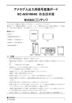
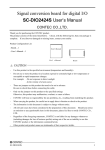
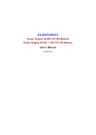
1
PC-HELPER
Signal Conditioner
4-Slots
ESC-4
User’s Manual
CONTEC CO.,LTD.
Check Your Package
Thank you for purchasing the CONTEC product.
The product consists of the items listed below.
Check, with the following list, that your package is complete.
items, contact your retailer
If you discover damaged or missing
Product Configuration List
- External Signal Conditioner…1
- Attachment fittings…2
- Brackets for front slots…3
- Screws for attachment fittings…4
- Brackets for rear slots…3
- Rubber feet…4
- Screws for securing front or rear bracket…12
- Screws for attaching rubber feet…4
- Power cable (for 125V)…1
- User’s Manual…1
- Clamp for fixing AC cable…1
Screws for securing front or
rear bracket
External Signal
Conditioner
Clamp for fixing
AC cable
ESC-4
Brackets
for front
slots
Attachment
fittings
Brackets
for rear
slots
Rubber feet
Power cable
Screws for
attachment fittings
Screws for attaching
rubber feet
User’s Manual
iii
Copyright
Copyright 2009 CONTEC CO., LTD.
ALL RIGHTS RESERVED.
No part of this document may be copied or reproduced in any form by any means without prior written
consent of CONTEC CO., LTD.
CONTEC CO., LTD. makes no commitment to update or keep current the information contained in
this document.
The information in this document is subject to change without notice.
All relevant issues have been considered in the preparation of this document.
Should you notice an
omission or any questionable item in this document, please feel free to notify CONTEC CO., LTD.
Regardless of the foregoing statement, CONTEC assumes no responsibility for any errors that may
appear in this document or for results obtained by the user as a result of using this product.
Trademarks
MS, Microsoft and Windows are trademarks of Microsoft Corporation.
names are trademarks of their respective holder.
iv
Other brand and product
ESC-4
Table of Contents
Check Your Package ..............................................................................................................................iii
Copyright................................................................................................................................................ iv
Trademarks ............................................................................................................................................. iv
Table of Contents .................................................................................................................................... v
1
BEFORE USING THE PRODUCT
1
About the Chassis.................................................................................................................................... 1
Features ............................................................................................................................................ 1
Signal conversion board (Option) ................................................................................................... 1
Customer Support.................................................................................................................................... 2
Web Site ........................................................................................................................................... 2
Limited One-Year Warranty ................................................................................................................... 2
How to Obtain Service............................................................................................................................ 2
Liability ................................................................................................................................................... 2
Safety Precautions................................................................................................................................... 3
Safety Information ........................................................................................................................... 3
Handling Precautions ....................................................................................................................... 3
Environment ..................................................................................................................................... 5
Inspection ......................................................................................................................................... 5
Storage.............................................................................................................................................. 5
Disposal ............................................................................................................................................ 5
2
SETUP
7
What is Setup?......................................................................................................................................... 7
Step 1 Preparation ................................................................................................................................... 8
Items to be prepared......................................................................................................................... 8
Names of major parts ....................................................................................................................... 9
Step 2 Installing the Signal Conditioner .............................................................................................. 10
Step 3 Attaching the bracket, power cable, etc. ................................................................................... 11
Attaching the bracket to the empty slot......................................................................................... 11
Connecting the power cable with this product.............................................................................. 12
Fixing the Power Cable.................................................................................................................. 13
How to Attach the Rubber Feet ..................................................................................................... 14
How to Attach the Attachment Fittings ........................................................................................ 14
Setup Troubleshooting .......................................................................................................................... 15
Symptoms and Actions .................................................................................................................. 15
3
ABOUT HARDWARE
17
Hardware specification ......................................................................................................................... 17
ESC-4
v
Physical dimensions ..............................................................................................................................18
vi
ESC-4
1. Before Using the Product
1 Before Using the Product
This chapter provides information you should know before using the product.
About the Chassis
This product is a box that can contain up to 4 signal conditioner (signal conversion) boards.
The signal conversion boards can be inserted through the slot-in system for effortless attachment or
replacement and easy maintenance.
Various feature enhancements can be achieved by adding or replacing signal conversion boards which
are separately available.
For example, SC-AIO1604G unifies the channels by changing the I/O range and/or other things for each
of them, and SC-DIO2424S enables switching sync/source by 8-points according to the signal source,
allowing a measurement using one board.
Features
- Max. four signal conversion boards can be connected.
You can connect Max. four signal conversion boards (SC-AIO16-4G, SC-DIO2424S).
- Slot-in system facilitating connection of a signal conversion board.
This product uses the slot-in system that makes it easier to connect a signal
conversion board without opening the cover of cabinet. Easy maintenance by
smooth connection and conversion
- Various feature enhancements can be achieved by replacing signal
conversion boards.
By adding or replacing the signal conversion board(s), various feature enhancements according to your
needs are possible.
Signal conversion board (Option)
Signal conversion board for analog I/O
Signal conversion board for digital I/O
: SC-AIO1604G
: SC-DIO2424S
Check the CONTEC’s Web site for more information on these signal conversion board.
ESC-4
1
1. Before Using the Product
Customer Support
CONTEC provides the following support services for you to use CONTEC products more efficiently
and comfortably.
Web Site
Japanese
English
Chinese
http://www.contec.co.jp/
http://www.contec.com/
http://www.contec.com.cn/
Latest product information
CONTEC provides up-to-date information on products.
CONTEC also provides product manuals and various technical documents in the PDF.
Free download
You can download updated driver software and differential files as well as sample programs available in
several languages.
Note!
For product information
Contact your retailer if you have any technical question about a CONTEC product or need its price,
delivery time, or estimate information.
Limited One-Year Warranty
CONTEC products are warranted by CONTEC CO., LTD. to be free from defects in material and
workmanship for up to one year from the date of purchase by the original purchaser.
Repair will be free of charge only when this device is returned freight prepaid with a copy of the
original invoice and a Return Merchandise Authorization to the distributor or the CONTEC group office,
from which it was purchased.
This warranty is not applicable for scratches or normal wear, but only for the electronic circuitry and
original products. The warranty is not applicable if the device has been tampered with or damaged
through abuse, mistreatment, neglect, or unreasonable use, or if the original invoice is not included, in
which case repairs will be considered beyond the warranty policy.
How to Obtain Service
For replacement or repair, return the device freight prepaid, with a copy of the original invoice. Please
obtain a Return Merchandise Authorization number (RMA) from the CONTEC group office where you
purchased before returning any product.
*
No product will be accepted by CONTEC group without the RMA number.
Liability
The obligation of the warrantor is solely to repair or replace the product. In no event will the
warrantor be liable for any incidental or consequential damages due to such defect or consequences that
arise from Safety Precautions.
Understand the following definitions and precautions to use the product safely.
2
ESC-4
1. Before Using the Product
Safety Precautions
Understand the following definitions and precautions to use the product safely.
Safety Information
This document provides safety information using the following symbols to prevent accidents resulting
in injury or death and the destruction of equipment and resources. Understand the meanings of these
labels to operate the equipment safely.
DANGER
DANGER indicates an imminently hazardous situation which, if not avoided, will
result in death or serious injury.
WARNING
WARNING indicates a potentially hazardous situation which, if not avoided, could
result in death or serious injury.
CAUTION
CAUTION indicates a potentially hazardous situation which, if not avoided, may
result in minor or moderate injury or in property damage.
Handling Precautions
DANGER
Do not use the product where it is exposed to flammable or corrosive gas.
an explosion, fire, electric shock, or failure.
Doing so may result in
CAUTION
-
Do not plug or unplug any board into or from the slot with this product powered.
Doing so may result in a malfunction, overheating, or fault.
Be sure to turn off this product and unplug their power cables before plugging or unplugging any
board.
-
Do not plug or unplug the cable interconnecting this product with this product powered.
-
This product must always be used standing horizontally.
Doing so may result in a malfunction, overheating, or fault.
-
If a specific slot is recommended for a board, plug the board into that slot.
result in a malfunction, overheating, fault, or damage.
-
When plugging or unplugging the power cable, be sure to hold it by the plug itself.
-
The power cable used must be compliant to the outlet voltage and plug type.
(The attached cable is for 125VAC.)
-
Since this product is a precision device, do not store or use it where it is subject to shock or
vibration. Also avoid any place where this product is exposed to direct sunlight, extremely high
humidity, or much dust.
-
Do not use or store the chassis where it is exposed to any chemical either directly or as vapor in the
air.
-
This product has ventilating slits to prevent it from overheating.
ventilating slits blocked or in an ill-ventilated place.
ESC-4
Failure to do so may
Avoid using the chassis with the
3
1. Before Using the Product
-
Do not use the chassis near equipment generating a strong magnetic field or noise.
Doing so may result in a malfunction, overheating, fault, or damage in the chassis, your PC, or
both.
-
It is very dangerous to use this product with water, liquid, or metal (conductive) chips left inside.
Be careful not to let such foreign matters in this product.
-
The specifications of this product are subject to change without notice for enhancement or quality
improvement.
Even when using the product continuously, be sure to read the manual and understand the contents.
-
Do not modify this product.
CONTEC will bear no responsibility for any problems, etc., resulting from modifying the product.
-
Regardless of the foregoing statements, CONTEC is not liable for any damages whatsoever
(including damages for loss of business profits) arising out of the use of or inability to use this
CONTEC product or the information contained herein.
4
ESC-4
1. Before Using the Product
Environment
Use this product in the following environment.
may overheat, malfunction, or cause a failure.
If used in an unauthorized environment, the chassis
Operating temperature
0 - 50°C
Humidity
20 - 80%RH (No condensation)
Corrosive gases
None
Floating dust particles
Not to be excessive
Inspection
Inspect the product periodically as follows to use it safely.
- Ventilating slits must neither be blocked nor have dust or foreign
matters adhering.
Storage
When storing this product, keep it in its original packing form.
(1) Wrap it in the packing material, then put it in the box.
(2) Store the package at room temperature at a place free from direct sunlight, moisture, shock,
vibration, magnetism, and static electricity.
Disposal
When disposing of the product, follow the disposal procedures stipulated under the relevant laws and
municipal ordinances.
ESC-4
5
1. Before Using the Product
6
ESC-4
2. Setup
2 Setup
This chapter explains how to set up the chassis.
Refer to the user’s manual for the signal conditioner as required.
What is Setup?
Setup means a series of steps to take before the product can be used.
Taking the following steps in this chapter sets up the ESC-4.
Step 1 Preparation
Step 2 Installing the Signal Conditioner
Step 3 Attaching the bracket, power cable, etc.
ESC-4
7
2. Setup
Step 1 Preparation
Configuration image
Figure 2.1. Configuration image
Items to be prepared
-
ESC-4
This product…(a)
Brackets for front slots…(b)
Brackets for rear slots…(c)
-
Signal Conditioner…(d) The photo is of the SC-DIO2424S.
SC-AIO1604G
SC-DIO2424S
(a)
8
(d)
(c)
(b)
ESC-4
2. Setup
Names of major parts
Front view
Power LED
Slot
(4 Slots)
Back view
Board supporting
lanes
Power Switch
Hole to attach the clamp for
fixing AC power cable
Figure 2.2. Names of major parts
ESC-4
9
2. Setup
Step 2 Installing the Signal Conditioner
CAUTION
-
Before installing the signal conditioner on this product, be sure to turn off this product and unplug
the power cables from wall outlets at the same time.
-
There are switches and jumpers on the signal conditioner that need to be set in advance.
Be sure to check these before installing this product.
Follow the procedure below to install the signal conditioner on this product.
(1) Unplug the power cable from this product.
(2) Remove the screws fixing the bracket on front/back side and then remove the bracket.
(3) Insert the board to one of the slots. The slot has the lane along which the board must be slid in.
(4) Fix the front / back side of board with screws.
Figure 2.3.
10
Installing the Signal Conditioner
ESC-4
2. Setup
Step 3 Attaching the bracket, power cable, etc.
Attaching the bracket to the empty slot
Figure 2.4. Attaching the brackets for front slots
Figure 2.5. Attaching the brackets for rear slots
CAUTION
Make sure that all the unused slot(s) are fitted with the bracket(s).
ESC-4
11
2. Setup
Connecting the power cable with this product
(1) Connect this product with the power cable.
Figure 2.6. Connecting the power cable with this product
(2) Connect the power cable to the wall outlet.
(3) Accidental removal of the AC cable can be prevented by securing it with the clamp for fixing AC
cable that can be attached to the hole beside the cable connector.
CAUTION
Make sure that the power switch is OFF before connecting the power cable.
product may malfunction or cause a failure.
12
Otherwise, this
ESC-4
2. Setup
Fixing the Power Cable
Clamp for fixing AC cable is bundled with this product.
(1) Attach the tip of clamp for fixing AC cable to the hole above the AC inlet.
Figure 2.7. Attaching the clamp for fixing AC cable
<1/3>
(2) Apply the clamp for fixing AC cable to the power cable.
Figure 2.7. Attaching the clamp for fixing AC cable
<2/3>
(3) Move the clamp for fixing AC cable as close to the AC inlet as possible, then tighten the clamp to
fasten the power cable.
Figure 2.7. Attaching the clamp for fixing AC cable
ESC-4
<3/3>
13
2. Setup
How to Attach the Rubber Feet
(1) Attach the rubber feet to the bottom side of this product by using screws, if necessary.
Figure 2.8. Attaching the rubber feet
How to Attach the Attachment Fittings
(1) The attachment fittings should be attached as shown below.
Attachment fittings
Screws for
attachment
fittings
Figure 2.9. Attach the Attachment Fittings
CAUTION
Rubber feet and attachment fitting are mutually exclusive.
on the operating condition.
14
Use either of them at a time depending
ESC-4
2. Setup
Setup Troubleshooting
Please confirm followings when the ESC-4 does not work.
Symptoms and Actions
The chassis won’t be turned on.
a.
Make sure that the power cable has been connected correctly.
b.
Make sure that the LED is turned on.
c.
Make sure that the power supply of this product is on.
d.
Make sure that you have followed the procedure in Chapter 2.
e.
Even though the chassis is still not turned on, check whether it is turned on with no board installed.
No PCI board on this product is detected.
f.
Make sure that the signal conditioner has been installed correctly.
g.
Make sure that the connection cable has been installed correctly. When connecting the connection
cable to the main chassis, insert the connector until it clicks into place.
h.
Make sure that the POWER LED on this product is turned on.
(a)
ESC-4
(c),(h)
(f)
15
2. Setup
16
ESC-4
3. About Hardware
3 About Hardware
Hardware specification
Table 3.1.
Specification
Item
Specification
Number of user-available slots
4
Power capacity (Max.)
+5VDC
AC input line voltage
100 - 240VAC
12A
Input frequency
50/60Hz
Inrush current
25A Peak(100VAC), 50A Peak(200VAC)
Maximum total power capacity
60W
Physical dimensions (mm)
242(W) x 262(D) x 115(H) (No protrusions)
Weight
3000g
Table 3.2.
Environmental specification
Item
Specification
Operating temperature
0 - 50ºC
Operating humidity
20 - 80%RH(No condensation)
Storage temperature
0 - 60ºC
Storage humidity
10 - 90%RH(No condensation)
Floating dust particles
Not to be excessive
Corrosive gases
None
CAUTION
The power supply and cooling fan in the ESC-4 is consumable, requiring replacement after use for a
certain period of time. Although each of the parts should be replaced after use for the following
period of time in principle, the life may be shortened depending on the operating environment.
Keep in mind that the lives of the parts may be extremely shortened if they are used where it is
either exposed to must dirt, metal chips or particles, or dust or affected by oil or corrosive gas.
Power supply : About 5 years (in an office environment kept at a temperature of 25°C and a
humidity of 60%)
-
ESC-4
Fan
: About 5 years (in an office environment kept at a temperature of 25°C and a
humidity of 60%)
17
3. About Hardware
Physical dimensions
CAUTION
-
When using this product, keep it at least 20mm away from any object such as the wall for cooling
purposes.
-
Attaching rubber feet to the chassis makes it 8mm taller.
Figure 3.1. Physical dimensions
18
ESC-4
ESC-4
User’s Manual
CONTEC CO., LTD.
March 2009 Edition
3-9-31, Himesato, Nishiyodogawa-ku, Osaka 555-0025, Japan
Japanese http://www.contec.co.jp/
English http://www.contec.com/
Chinese http://www.contec.com.cn/
No part of this document may be copied or reproduced in any form by any means without prior written
consent of CONTEC CO., LTD.
[03172009]
[01292009]
03172009_rev2
Management No.
Parts No.
A-51-647
LYKB582