1
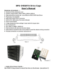
GS1000 SE
English version
◈ Please read this manual thoroughly before installation.
◈ Please visit the GS1000 web page at Zalman’s website to view the GS1000
installation video.
E-mail: [email protected]
www.zalman.com
GS1000 SE
▣ Contents
1. Cautionary Notes
3
2. Specifications
4
3. Parts List
5
4. Installation
8
5. Options
2
14
GS1000 SE
1 Cautionary Notes
English
1) Please thoroughly read and understand the contents of this User Manual prior
to installation.
2) Check the components list and condition of the product before installation. If
any problem is found, contact the retailer to obtain a replacement.
3) Refrain from touching any moving parts to prevent injuries.
4) Please refer to the manual for cable setup/installation. Incorrect installation can
lead to short-circuiting and/or damage(s).
5) Do not block the front and rear air vents.
6) Place on a flat, stable surface with good ventilation, and avoid areas with direct
sunlight, oil, water or excessive moisture.
7) Do not cleanse any surface with chemical cleaners or solvents.(chemicals
including but not limited to: industrial brightener, wax, benzene, alcohol, paint
thinner, mosquito repellent, aromatics, lubricant, detergent etc.)
8) Please wear gloves during the installation process to prevent injuries.
9) The specifications of any product may change without prior notice to improve
performance
Disclaimer) Zalman Tech Co., Ltd. is not responsible for any damages due
to extemal causes, including but not limited to, improper use,
problems with electrical power, accident, neglect, alternation,
repair, improper installation, or improper testing.
3
GS1000 SE
2 Specifications
Type
Dimensions
(D x W x H)
Weight
Material(s)
Color Options
Motherboard Compatibility
PSU Compatibility
PCI/AGP card Compatibility
640mm x 260mm x 570mm (including feet)
(25.2 x 10.2 x 22.4 )
17.4kg (38.4lb)
Aluminum / ABS / Steel
Black / Titanium
E-ATX / Standard ATX / microATX
Standard ATX / ATX12V
Full Size
5.25" Bays
x 4 (2 can serve as 3.5")
3.5" Bays
x 6 (Hot Swap Function Optional)
Cooling Components
Expansion Slots
(Tool Free Bolts provided)
Front I/O port
4
Full Tower
Top Vent: 120mm Fan Vent x 2
(1 Fan included, 1 optional)
Rear Vent: 120mm Fan Vent x 1
(1 Fan included)
Bottom Vent: 120mm Fan Vent x 2
(Fans optional)
x 7 slots
USB x 2
IEEE1394(Firewire) x 1
Headphone x 1
Mic x1
GS1000 SE
3 Parts List
English
1) GS1000 SE
POWER
USB 2.0
Headphones
Mic
Front View
Rear View
IEEE 1394
Top View
Side View
5
GS1000 SE
2) GS1000 SE Blow-Up Diagram
⑤
⑦
⑧
④
③
⑨
②
⑩
①
⑪
Part No.
6
Part Name
Qty
HDD Cover
HDD Tray
Part No.
Part Name
Qty
2
Side Panel
2
6
PSU Bracket
1
“2 in 1”Bracket
2
PSU Fan Bracket
1
5.25
" Bay Cover
2
Rear Foot
1
Chassis
1
Front Foot
1
Top Cover
1
GS1000 SE
3) GS1000 SE Parts
Part Name
Qty
Foot (Front/Rear)
1
CPU 12V
Role
English
Diagram
Support
CPU Power Extension
1
Cable
Extension Cable
microATX M/B Installation
M/B Stand Off
20
HDD Screws
12
PSU Screws
24
(silver)
HDD Installation (black)
PSU, Motherboard
Installation (black)
Foot Fixing Screws
4
Feet Assembly (black)
Hand Screws
4
5.25
" Bay Installation
FDD Cover
1
FDD Installation
Cable Tie
10
Cable Management
1
Fan RPM control
(white/low noise/5V,
black/full speed/12V)
ZM-MC1
(Multi Connector)
7
GS1000 SE
4 Installation
1) Feet Assembly
Front Foot
Rear Foot
Foot Fixing Screw
2) Side Panel Removal
1
8
2
GS1000 SE
3) PSU Installation
(1) PSU Bracket Removal
A Type
English
PSU Screw
B Type
(2) PSU Bracket Assembly
A Type
B Type
Tip
▶A Type : Please position the PSU’s intake facing downwards to optimize PSU
cooling.
▶B Type : Please position the PSU’s intake facing upwards to optimize system
cooling.
※ If the system is in a dusty environment, please use the B Type configuration.
9
GS1000 SE
4) Motherboard Installation
M/B Stand Off
PSU Screw
micro ATX motherboard
Server motherboard
※ When installing a micro ATX or server motherboard, please install the
M/B Stand Offs as shown in the diagram.
5) Hot Swap HDD Installation
" HDD Removal
(1) 3.5
1
2
3
Press the corners of the Hot Swap
Tray towards the center and pull out
as shown in the diagram.
10
GS1000 SE
(2) HDD Tray HDD installation
2
Push the Hooks located on the underside
of the HDD Tray and push in the direction
as shown above.
3
English
1
Diagram of “open” HDD Tray
4
3.5"
3.5"
HD
D
HD
D
Please check that the Tray’s metal pins
are aligned with the HDD's fixing holes.
5
6
3.5"
HD
D
Caution
※ Please secure the HDDs with
bolts as shown in the diagram
when transporting the case
with HDDs installed.
※ Be sure to install the HDD(s)
right-side up or the HDD(s)
will not operate properly.
HDD Screw
11
GS1000 SE
6) 5.25˝ Drive Installation
(1) ODD Installation
1
2
3
4
Screw
HandScrew
Screw
Hand
Hand
Screw
(2) FDD Installation
1
2
4
5
3
(3) HDD Installation (additional HDD installation in a 5.25 bay)
1
12
2
3
GS1000 SE
7) Front I/O Cable Connection
Caution
※ Mixing the IEEE1394a and USB2.0 cables can cause severe damage
to the system.
※ The Power LED will not function properly if connected with the wrong
polarity (+/-). Please check the motherboard’s manual before
connecting.
English
For USB 2.0, IEEE1394a, and audio components, please refer to the
motherboard's manual.
13
GS1000 SE
5 Options
1) Optional Top Panel 120mm Fan Installation
1
2
3
4
2) Optional Bottom Panel 120mm Fan Installation
Bottom Panel Center Fan Installation
14
Bottom Panel Rear Fan Installation
GS1000 SE
3) ZM-MC1(Multi Connector)
5V Connector
900~2300 RPM
(white)
PSU 4-Pin
Connector
English
(1) Connect the 4-Pin Connector to the PSU as show in the below diagram.
(2) Connect the case fan(s) to the desired voltage / speed connector(s).
(120mm, 92mm fan)
12V Connector
1800~2800RPM
(black)
4) Hot Swap PCB Installation (Optional)
(1) Up to 2 Hot Swap PCBs(sold separately) can be installed.
(2) Each Hot Swap PCB can connect up to 3 S-ATA HDDs.
15
MEMO
16