1
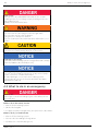
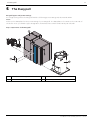
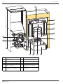
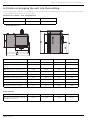
Installation Manual Easypell® 16 — 32kW ENGLISH 200014_EN 1.2 · www.easypell.com Title: Installation Manual Easypell® 16 — 32kW Article number: 200014_EN 1.2 Version valid from: 09/2015 Approved: Wohlinger Christian Author Eco Engineering 2050 GmbH A-4132 Lembach, Mühlgasse 9 Tel.: +43 (0) 72 86 / 74 50 Fax.: +43 (0) 72 86 / 74 50 – 10 E-Mail: [email protected] www.easypell.com © by Eco Engineering 2050 GmbH Subject to modifcations Contents 1 Dear Customer . . . . . . . . . . . . . . . . . . . . . . . . . . . . . . . . . . . . . . . . . . . . . . . . . . . . . . . . . . . . . . . . . . . . . . . . . . . . . . . . . . . . . . . . . . . . . . . . . . . . . . . . . . . . . . . . . . . . . . . . . . . . . . . . . . . . . . . . . . . . . . . 4 2 Types of safety warning sign . . . . . . . . . . . . . . . . . . . . . . . . . . . . . . . . . . . . . . . . . . . . . . . . . . . . . . . . . . . . . . . . . . . . . . . . . . . . . . . . . . . . . . . . . . . . . . . . . . . . . . . . . . . . . . . . . . . . . . . 5 3 Prerequisites for installing a pellet boiler . . . . . . . . . . . . . . . . . . . . . . . . . . . . . . . . . . . . . . . . . . . . . . . . . . . . . . . . . . . . . . . . . . . . . . . . . . . . . . . . . . . . . . . . . . . . . . . . . . 6 3.1 Guidelines and standards for installing a pellet boiler .................................................................................. 6 3.2 Central heating room ................................................................................................................................... 6 3.3 Flue gas system.............................................................................................................................................7 3.4 Safety systems ............................................................................................................................................. 8 3.5 Operation of a pellet boiler with an existing boiler ...................................................................................... 8 4 Warnings and safety instructions . . . . . . . . . . . . . . . . . . . . . . . . . . . . . . . . . . . . . . . . . . . . . . . . . . . . . . . . . . . . . . . . . . . . . . . . . . . . . . . . . . . . . . . . . . . . . . . . . . . . . . . . . . . . . . . 9 4.1 Basic safety instructions ............................................................................................................................... 9 4.2 Warning signs............................................................................................................................................... 9 4.3 What to do in an emergency....................................................................................................................... 10 5 The Ea syp ell . . . . . . . . . . . . . . . . . . . . . . . . . . . . . . . . . . . . . . . . . . . . . . . . . . . . . . . . . . . . . . . . . . . . . . . . . . . . . . . . . . . . . . . . . . . . . . . . . . . . . . . . . . . . . . . . . . . . . . . . . . . . . . . . . . . . . . . . . . . . . . . . . . . 11 6 Bringing the pellet boiler into the central heating room . . . . . . . . . . . . . . . . . . . . . . . . . . . . . . . . . . . . . . . . . . . . . . . . . . . . . . . . . . . . . . . . . . . . . . . . 13 6.1 Transport...................................................................................................................................................... 13 6.2 Notes on bringing the unit into the building ............................................................................................... 14 6.3 Casing parts ................................................................................................................................................ 16 6.4 Dismantling the burner casing and the burner ........................................................................................... 17 6.4.1 Dismantling the burner casing and burner ............................................................................................... 17 6.4.2 Dismantling the boiler door...................................................................................................................... 19 6.4.3 Dismantling the boiler casing.................................................................................................................. 20 7 Adjusting power rating . . . . . . . . . . . . . . . . . . . . . . . . . . . . . . . . . . . . . . . . . . . . . . . . . . . . . . . . . . . . . . . . . . . . . . . . . . . . . . . . . . . . . . . . . . . . . . . . . . . . . . . . . . . . . . . . . . . . . . . . . . . . . . . 21 7.1 Installing the turbulators and closure plugs................................................................................................. 21 8 Connecting up the hydrauli cs . . . . . . . . . . . . . . . . . . . . . . . . . . . . . . . . . . . . . . . . . . . . . . . . . . . . . . . . . . . . . . . . . . . . . . . . . . . . . . . . . . . . . . . . . . . . . . . . . . . . . . . . . . . . . . . . . . . 23 9 The boiler controller . . . . . . . . . . . . . . . . . . . . . . . . . . . . . . . . . . . . . . . . . . . . . . . . . . . . . . . . . . . . . . . . . . . . . . . . . . . . . . . . . . . . . . . . . . . . . . . . . . . . . . . . . . . . . . . . . . . . . . . . . . . . . . . . . . . 24 9.1 Plugs on the boiler control unit ....................................................................................................................25 9.2 Cable routing.............................................................................................................................................. 26 9.3 Wiring diagrams ..........................................................................................................................................27 10 Starting up for the first time . . . . . . . . . . . . . . . . . . . . . . . . . . . . . . . . . . . . . . . . . . . . . . . . . . . . . . . . . . . . . . . . . . . . . . . . . . . . . . . . . . . . . . . . . . . . . . . . . . . . . . . . . . . . . . . . . . . . 28 11 Starting the pellet boiler . . . . . . . . . . . . . . . . . . . . . . . . . . . . . . . . . . . . . . . . . . . . . . . . . . . . . . . . . . . . . . . . . . . . . . . . . . . . . . . . . . . . . . . . . . . . . . . . . . . . . . . . . . . . . . . . . . . . . . . . . . . . 29 12 Controller for heating circuits and DHW . . . . . . . . . . . . . . . . . . . . . . . . . . . . . . . . . . . . . . . . . . . . . . . . . . . . . . . . . . . . . . . . . . . . . . . . . . . . . . . . . . . . . . . . . . . . . . . . 30 12.1 Version A .................................................................................................................................................... 30 12.1.1 Commissioning controller version A ........................................................................................................ 33 12.1.2 Selecting the set DHW temperature ....................................................................................................... 34 12.1.3 Setting the time program for DHW heating ........................................................................................... 35 12.1.4 Setting the time....................................................................................................................................... 38 12.1.5 Status display .......................................................................................................................................... 39 12.2 Version B ................................................................................................................................................... 39 12.2.1 Commissioning controller version B ........................................................................................................ 41 12.2.2 Setting the boiler heating period............................................................................................................ 42 12.2.3 Setting the time ...................................................................................................................................... 45 12.2.4 Status display ......................................................................................................................................... 46 13 Malfunctions . . . . . . . . . . . . . . . . . . . . . . . . . . . . . . . . . . . . . . . . . . . . . . . . . . . . . . . . . . . . . . . . . . . . . . . . . . . . . . . . . . . . . . . . . . . . . . . . . . . . . . . . . . . . . . . . . . . . . . . . . . . . . . . . . . . . . . . . . . . . . . . 47 13.1 Malfunctions - what to do .......................................................................................................................... 47 13.2 Fault texts.................................................................................................................................................. 47 14 Appendix . . . . . . . . . . . . . . . . . . . . . . . . . . . . . . . . . . . . . . . . . . . . . . . . . . . . . . . . . . . . . . . . . . . . . . . . . . . . . . . . . . . . . . . . . . . . . . . . . . . . . . . . . . . . . . . . . . . . . . . . . . . . . . . . . . . . . . . . . . . . . . . . . . . . . 51 14.1 Checklist for checking the heating system................................................................................................. 51 14.2 Retrofit motor cleaning device ................................................................................................................. 53 15 Spare parts . . . . . . . . . . . . . . . . . . . . . . . . . . . . . . . . . . . . . . . . . . . . . . . . . . . . . . . . . . . . . . . . . . . . . . . . . . . . . . . . . . . . . . . . . . . . . . . . . . . . . . . . . . . . . . . . . . . . . . . . . . . . . . . . . . . . . . . . . . . . . . . . . 56 16 Technical data . . . . . . . . . . . . . . . . . . . . . . . . . . . . . . . . . . . . . . . . . . . . . . . . . . . . . . . . . . . . . . . . . . . . . . . . . . . . . . . . . . . . . . . . . . . . . . . . . . . . . . . . . . . . . . . . . . . . . . . . . . . . . . . . . . . . . . . . . . . . 58 Installation Manual Easypell® 16 — 32kW 4 Dear Customer 1 Dear Customer • This manual is intended to help you operate the product safely, properly and economically. • Please read this manual right through and take note of the safety warnings. • Keep all documentation supplied with this unit in a safe place for future reference. Please pass on the documentation to the new user if you decide to part with the unit at a later date. • Please contact your authorised dealer if you have any questions. 200014_EN 1.2 Types of safety warning sign 5 2 Types of safety warning sign The warning signs use the following symbols and texts. Types of safety warning sign 1. Risk of injury 2. Consequences of risk 3. Avoiding risk 1. Risk of injury: Danger - indicates a situation that could lead to death or lifethreatening injury. Warning - indicates a situation that could lead life-threatening or serious injury. Caution - indicates a situation that could lead to injury. Note - indicates a situation that could lead to property damage. 2. Consequences of risk Effects and consequences resulting from incorrect operation. 3. Avoiding risk Observing safety instructions ensures that the heating system is operated safely Installation Manual Easypell® 16 — 32kW 6 Prerequisites for installing a pellet boiler 3 Prerequisites for installing a pellet boiler You must fulfill the following conditions before operating a fully automatic pellet boiler. 3.1 Guidelines and standards for installing a pellet boiler Overview of standards and guidelines applying to the installation of a pellet boiler. Check whether you need to obtain planning permission or approval from the authorities for installing a new heating system or changing your existing system. Legislation in your country must be observed. Flue gas system EN 13384–1 Legislation in your country must be observed. Building and fire prevention regulations Type of installation Sound insulation Legislation in your country must be observed. FC 42x Fireplace with a flue gas fan for connection to an air exhaust system. The combustion air line from air shaft and the connecting piece to the chimney are part of the fireplace. FC 52x Fireplace with a flue gas for connection to a chimney. The combustion air line from outside and the connecting piece to the chimney are part of the fireplace. DIN 4109 Please note the building-unique demands on sound insulation. 3.2 Central heating room The pellet boiler is installed in the central heating room. 1. Safety instructions for the heating room Risk of fire Do not store flammable materials or liquids in the vicinity of the pellet boiler. Do not permit unauthorised persons to enter the central heating room - children are to be kept out. Always close the boiler door. 2. Air supply and ventilation of central heating room The central heating room must be fitted with air supply and ventilation openings (at least 200cm2). Legislation in your country must be observed. 3. Combustion air supply The pellet boiler needs a supply of combustion air. Never operate the pellet boiler if the air intake openings are partially or completely closed. Contaminated combustion air can cause damage to the pellet boiler. Never store of use cleaning detergents containing chlorine, nitrobenzene or halogen in the room where the heating system is installed, if combustion air is drawn directly from the room. Do not hang out washing in the central heating room. Prevent dust from collecting at the combustion air intake to the pellet boiler. 4. Damage due to frost and humid air The central heating room must be frost-proof to ensure trouble-free operation of the heating system. The temperature of the central heating room must not fall below –3°C and must not exceed +30°C. The air humidity in the central heating room must not exceed 70%. 5. Danger for animals Make sure that household pets and other small animals cannot enter the central heating room. Fit mesh 200014_EN 1.2 Flue gas system 7 over any openings. 6. Flooding If there is a risk of flooding, switch off the pellet boiler in good time and disconnect from the power supply before water enters the central heating room. You must have all components that come into contact with water replaced, before you start up the pellet boiler again. 7. Cleaning Clean the flue gas tube and chimney regularly. Oxidation of chimney Do not use metal brushes to clean chimneys made of stainless steel. Legislation in your country must be observed. 3.3 Flue gas system The flue gas system consists of a chimney and a flue gas tube. The flue gas tube connects the pellet heating system to the chimney. The chimney leads the flue gas from the pellet heating system out into the open. 1. Design of the chimney The dimensions and design of the chimney is very important. The chimney must be able to ensure sufficient draft to safely draw away the flue gas regardless of the status of the boiler. Low flue gas temperatures can cause sooting and moisture damage on chimneys that are not insulated. For this reason moisture-resistant chimneys (stainless steel or ceramic) should be used. Chimneys made of plastic are not permitted. An existing chimney that is not damp-resistant needs to be rennovated before use. Boiler size Easypell 16 Easypell 20 Easypell 25 Easypell 32 Flue gas tube diameter (at boiler) – [mm] 130 Chimney diameter as per chimney calculation, EN 13384–1 Chimney design 150 damp-resistant 2. Flue gas temperature Boiler type Easypell 16 Easypell 20 Easypell 25 Flue gas temperature rating 160°C Flue gas temperature partial load 100°C Easypell 32 The dewpoint of flue gas with wood pellets (max. 10% water content) is approx. 50°C. 3. Chimney draft The diameter of the chimney must be selected based on a chimney calculation according to EN 13 384–1. The suction effect of the chimney draft must extend as far as the chimney connection. The maximum flow rate that can be drawn through the chimney limits the maximum performance of the pellet boiler. The boiler performance must be reduced if the chimney does not possess the necessary cross-section. This may only be performend by authorised personnel. Installation Manual Easypell® 16 — 32kW 8 Safety systems 3.4 Safety systems The following safety measures are the prerequisite for safe operation of your system. Emergency stop switch Every heating system must be able to be switched off with an Emergency Stop switch. The Emergency Stop switch must be inside the central heating room. Safety valve The hydraulic system must be equipped with a safety valve. This valve opens when the pressure inside the heating system increases to max. 3 bar. The safety valve must: –be installed at the highest point of the boiler, –must not be locked, –and must be within 1 metre of the boiler. Safety temperature sensor The pellet boiler is equipped with a safety temperature sensor. This is located on the pellet boiler. If the boiler temperature exceeds 95°C then the heating system switches off. Expansion tank All heating systems must be equipped with a pressurised expansion tank. The plumber or heating system installer must dimension the expansion tanks according to the dimensions of the hydraulic system. Starting up Starting up for the first time has to be performed only by an authorized service technician. 3.5 Operation of a pellet boiler with an existing boiler There are different regulations in the different European countries. Please mind the prescription of your country. 200014_EN 1.2 Warnings and safety instructions 9 4 Warnings and safety instructions Observing safety instructions ensures that the heating system is operated safely. 4.1 Basic safety instructions • Never get yourself into danger; give own safety the utmost priority. • Keep children away from the central heating room and storage room. • Observe all safety warnings on the boiler and in this user manual. • Observe all instructions relating to maintenance, servicing and cleaning. • The pellet heating system may only be installed and started up for the first time by an authorised plumber. Professional installation and start up is the prerequisite for safe and economical operation. • Never make any changes to the heating system or flue gas system. • Never close or remove safety valves. 4.2 Warning signs Risk of poisoning Make sure that the pellet boiler is supplied with sufficient combustion air. The openings in the combustion air inlet must never be partially or completely closed. Ventilation systems, central vacuum cleaning systems, extractor fans, air conditioning systems, flue gas blowers, dryers or similar equipment must never be allowed to draw air from the central heating room and cause a drop in pressure. The boiler must be connected tight to the chimney using a flue gas tube. Clean the chimney and the flue gas tube at regular intervals. The central heating room and pellet storage room must be sufficiently supplied with air and ventilated. Before entering the storage room it must be ventilated with sufficient air and the heating system switched off. Risk of electric shock Switch off the system before performing work on the boiler. Risk of explosion Never burn petrol, diesel, engine oil or other explosive materials. Never use liquids or chemicals to ignite the pellets. Switch off the heating system before filling the storage room. Installation Manual Easypell® 16 — 32kW 10 Risk of fire Do not store any flammable materials in the central heating room. Do not hang out any washing in the central heating room. Always close the boiler door. Risk of burns Do not touch the flue spigot or the flue gas tube. Do not reach into the ash chamber. Use gloves to empty the ash box. Do not clean the boiler until it has been allowed to cool down. Risk of cut injuries due to sharp edges. Use gloves for performing all work on the boiler. Damage to property Heat the pellet heating system using pellets that comply with EN 14961-2 class A1 and A2 only. Damage to property Do not use the heating system if it, or any of its components, come into contact with water. If water damage occurs, have the heating system checked by an service technician and have any damaged parts replaced. 4.3 What to do in an emergency Risk to life Never get yourself into danger; give own safety the utmost priority. What to do in the event of a fire • Switch off the heating system. • Call the fire brigade • Use approved fire extinguishers (fire protection class ABC). What to do if you smell smoke • Switch off the heating system. • Close the doors leading to living areas. • Ventilate the central heating room. 200014_EN 1.2 What to do in an emergency The Easypell 11 5 The Easypell Easypell types and power ratings Eco Engineering offers the Easypell with the following power ratings: 16, 20, 25 and 32kW. Note: Refer to the data plate for the power rating of your Easypell. The data plate is located on the rear side of the boiler. Here you find the type designation, manufacturer's serial number and year of build. Key components of the Easypell 1 Boiler (heat exchanger) 3 Boiler controller 2 Burner 4 Pellet hopper Installation Manual Easypell® 16 — 32kW 12 The Easypell 1 Burner plate 7 Suction fan 2 Flame tube 8 Anti-blowback system 3 Heat exchanger 9 Burner auger 4 Boiler water 10 Electronic ignition 5 Boiler insulation 11 Combustion chamber sensor 6 Combustion chamber cover 12 Ash box 200014_EN 1.2 Bringing the pellet boiler into the central heating room 13 6 Bringing the pellet boiler into the central heating room This section describes the prerequisites as well as the working sequence required. 1. Transport 2. Notes on bringing the unit into the building 3. Casing parts 4. Dismantling the casing parts 6.1 Transport Eco Engineering supplies the pellet boiler on a pallet. The pellet boiler is ready to be connected. The control unit for the boiler controller is integrated into the control panel. If it is not possible to bring the boiler into the building at ground level, remove the casing, the burner, the boiler controller and the pellet hopper. This will reduce the weight of the unit and make it easier to carry. Contamination and corrosion Make sure that the pellet boiler is located under a roof if it needs to be stored outside before it is transported/ brought into the building. Installation Manual Easypell® 16 — 32kW 14 Notes on bringing the unit into the building 6.2 Notes on bringing the unit into the building Before bringing the unit into the building, check the dimensions of all doors to ensure that the boiler has sufficient clearance and can be set up properly. Minimum door width — max. unit dimension Easypell 16 / 20 16 — 20 kW 690 mm Easypell 25 / 32 25 — 32 kW 720 Boiler dimensions Dimensions in mm Easypell 16 Easypell 20 Easypell 25 Easypell 32 A: flow- return 905 905 1110 1110 B: overall width of pellet boiler 1210 1210 1227 1227 B1: Width with cleaning lever 1206 1206 1232 1232 C: width of boiler casing 695 695 728,5 728,5 D: Hight flue gas tube 645 645 844 844 E: Diameter flue gas tube 130 130 150 150 H: height of boiler casing 1091 1091 1242 1242 F: height hopper 1267 1267 1517 1517 T: depth of boiler casing 752 752 796,5 796,5 Easypell 16 Easypell 20 Easypell 25 Easypell 32 350 350 430 430 Boiler Weight Dimensions in kg Weight of boiler with casing, hopper and burner 200014_EN 1.2 Notes on bringing the unit into the building 15 Minimum clearance dimensions required Note: To install the heating system properly and ensure economical operation, you need to make sure that minimum clearance dimensions indicated below are observed when setting up the boiler. In addition, make sure that legislation in your country is complied with relating to the minimum clearance of the flue gas tube. a Min. clearance of flue gas connection from wall or part of building 450 mm b Min. clearance of side of boiler from wall or part of building 200 mm c Min. clearance of front of boiler from wall or part of building 700 mm d Min. clearance of side of burner from wall or part of building 300 mm e Min. room height 1950 mm Note: Legislation in your country must be observed! Placement of rubber plates The pellet heating boiler must be placed on the supplied rubber plates. Installation Manual Easypell® 16 — 32kW 16 Casing parts 6.3 Casing parts The boiler is protected by a casing on all sides. The casing parts prevent contact with hot, moving and live components. They also give Easypell pellet boilers a unique appearance. 1 Pellet hopper casing cover 4 Boiler door 2 Boiler casing cover 6 Pellet hopper casing 3 Boiler side panel 7 Boiler rear panel 200014_EN 1.2 Dismantling the burner casing and the burner 17 6.4 Dismantling the burner casing and the burner Dismantle the pellet boiler as far as necessary if site conditions require, so that the unit can be brought safely into the building. The complete dismantling of all components described here is divided into the following sections: 1. Dismantling the burner casing and the burner 2. Dismantling the boiler door 3. Dismantling the boiler casing 6.4.1 Dismantling the burner casing and burner Installation Manual Easypell® 16 — 32kW 18 200014_EN 1.2 Dismantling the burner casing and burner Dismantling the boiler door 19 6.4.2 Dismantling the boiler door Installation Manual Easypell® 16 — 32kW 20 6.4.3 Dismantling the boiler casing 200014_EN 1.2 Dismantling the boiler casing Adjusting power rating 21 7 Adjusting power rating On Eco Engineering pellet boilers the effective heat exchanger area can be changed within a assembly group. This involves opening or closing the heat exchanger tubes. The power rating of the pellet boiler is adjusted as a result. Eco Engineering supplies the pellet boilers in one of two sizes / outputs. Always observe the rating on the nameplate. The EasyPell 16 / 20 must always be set at or between 16 to 20KW. The EasyPell 25 / 32 must always be set at or between 25 to 32KW. There can be no exception to this! 7.1 Installing the turbulators and closure plugs Heat transfer takes place in the heat exchanger tubes. The heat exchanger tubes are fitted with cleaning springs that also act as turbolators. On the Easypell 16 and Easypell 25 boilers, some of these heat exchangers are sealed off with sealing caps. In this way, the heat exchanger area is adapted to the rated output. Sealing caps: Increasing the boiler power rating 1. Remove the closure plugs from the ends of the heat exchanger tubes. 2. Insert the turbulators supplied into the heat exchanger tubes. 3. Hook the turbulators onto the ring of the cleaning system. Reducing the boiler power rating 1. Unhook the turbulators from the ring of the cleaning system. 2. Remove the cleaning springs/turbulators from the heat exchanger tubes. 3. Close off the heat exchanger tubes using the closure plugs supplied. Number of cleaning springs (tubulators) to be removed/installed: Boiler power ratings as per data plate Factory-set boiler power rating 16 kW 16 kW No adjustment required 20 kW 16 kW Insert another 4 turbulators 25 kW 25 kW No adjustment required 32 kW 25 kW Insert another 4 turbulators Installation Manual Easypell® 16 — 32kW 22 Installing the turbulators and closure plugs Only the adjustment of the system by an authorized Eco Engineering service technician can guarantee an optimal level of efficiency and with that a low-emission operation. Starting up for the first time has to be performed only by an authorized Eco Engineering service technician. 200014_EN 1.2 Connecting up the hydraulics 23 8 Connecting up the hydraulics The hydraulic connections are located on the rear side of the boiler. Risk of explosion You may connect up the pellet boiler only after an authorised plumber has installed the hydraulic system completely with all safety devices. Water damage, damage to pellet boiler Only an authorised plumber may connect up hydraulics on the pellet boiler. Check the hydraulic system for leaks before starting up. 1. Hydraulic schematics Always refer to the Eco Engineering hydraulic schematics when connecting up the pellet boiler. The Eco Engineering hydraulic schematics are available from your Eco Engineering sales partner or from the Eco Engineering website. 2. Connections The connections between the pellet boiler and the hydraulic system must be disconnectable. 3. Drain connection When you install the pellet boiler, remove the plug from the ENTLEERUNG connection and fit a 1/2" diameter shut-off valve. 1 Feed 2 Return 3 Drain connection Installation Manual Easypell® 16 — 32kW 24 The boiler controller 9 The boiler controller The boiler controller is located behind the front cover of the boiler. It is used to control the combustion procedere and the fuel-feeding system. The boiler controller is connected to the operating device by a bus-connection. The operating device is located in the boiler door. Visualizing of measuring values and ajdustment of desired values and parameters are accomplished through through the operating device. Fuse type secured outputs 1 F1: Fuse T 3,15A LUFT, ES, ZUEND 2 F2: Fuse T 3,15A UW, RM, SZ 3 F3: Fuse T 315mA internal supply 4 F5: Fuse T 2A KAPRA, DigIn1 Damage of property If you change microfuses, ensure correct current rating 200014_EN 1.2 Plugs on the boiler control unit 25 9.1 Plugs on the boiler control unit All sensors and actuators are fully wired ready for connection. A plug-in connection is used for connecting to the boiler controller. Always ensure that the labelling of the plug corresponds to that of the plug-in position. Designation of plug-in position Voltage Name of sensors, motors and pumps BSK 123456 24 Volt UW 13 PE N 230 Volt DHW pump/ Accumulator pump HK N PE 14 230 Volt Only active if a sensor is connected to terminal 43/44. ZUEND N PE 22 230 Volt Ignition ES 1 2 3 N PE 6 230 Volt Burner motor SZ 17 PE N 230 Volt Flue gas fan RM 15 PE N 230 Volt Motor boiler cleaning device — optional LUFT N PE 11 230 Volt Burner fan STB 17 PE 19 230 Volt Safety temperature sensor NETZ L PE N 230 Volt Power supply boiler control unit AOUT PWM 1 12 230 Volt PWM for speed controlled high-efficiency pump FRT 13 12 24 Volt Combustion chamber sensor UP 432 24 Volt Negative draft measuring KF 98 24 Volt Boiler sensor AF 41 42 24 Volt not used WW 43 44 24 Volt DHW sensor Flame return gate (Belimo) Note: (Only use for controller version A) DigIn1 15 16 GN 24 Volt Pilot switch for hopper KAPRA 345 24 Volt Capacitive sensor – burner BR1 87 24 Volt Burner contact for external heating controller JMP — — Jumper for speed controlled high-efficiency pump Installation Manual Easypell® 16 — 32kW 26 9.2 Cable routing Reroute cables after dismantling the casing or other system components. Risk of electric shock Switch off the system before performing work on the boiler. Note the following points to ensure the cables are routed securely: Cables must not be routed: • over moving parts, • over hot parts, • or over sharp edges. Cables must be: • routed in the cable ducts provided and • through cable leadthroughs, • tied together, • and secured with cable ties at the points provided. Risk of electric shock Check cables for damage. Replace any cables that are damaged. Damage to the boiler controller Before fitting the casing components, make sure that all cables are connected to the correct points on the controller! Failure to do so can lead to damage to the controller, and such damage is not covered by warranty! 200014_EN 1.2 Cable routing Wiring diagrams 27 9.3 Wiring diagrams The wiring diagrams for the boiler control unit provide detailed technical information for certified installers. Only certified installers or electricians under the direction of a certified installer may connect to the controller. Risk of electric shock Only an authorised installer may connect the pellet boiler to the power supply. Always disconnect / de-energize the power supply before working on the boiler. Installation Manual Easypell® 16 — 32kW 28 Starting up for the first time 1 0 Starting up for the first time After bringing in the boiler, connecting up the hydraulics and power supply, the unit can be started up for the first time. Density of the combustion chamber To ensure a trouble-free operation, the density of the combustion chamber must be given. Note: The unit must be started up for the first time by an authorised Eco Engineering service technician. Note: Use the checklist enclosed to document the start-up procedure. Material Damage The allowed operation temperature of the boiler controller is between 5 and 40°C. 200014_EN 1.2 Starting the pellet boiler 29 1 1 Starting the pellet boiler Navigation-icons Iconview Description Use the up arrow to return to the previous menu screen. Use the down arrow to arrive at the next menu screen. When this symbol is displayed, the set value can be changed. When this function is selected, the value can be changed by pressing the arrow keys. When this function is selected, you leave the menu without saving the changed value. Icons System status Iconview Description Run down time Heating full power Container cover is open OFF Ignition Boiler cleaning Note: This message appears when the container cover has been open for longer than 20 seconds. Warning Installation Manual Easypell® 16 — 32kW 30 Controller for heating circuits and DHW 1 2 Controller for heating circuits and DHW In principle, 2 versions are available: Version A: • (max. 2) room thermostats are used for controlling the heating circuits. • The boiler controller features a time program for controlling DHW heating. The required DHW sensor is included in the scope of supply. Version B: • An external controller is used for controlling the heating circuits and DHW heating. 12.1 Version A A control function is integrated into the boiler controller, which enables a maximum of 2 heating circuits without mixer (radiators) to be controlled using a room thermostat. Furthermore, a control function for domestic hot water is integrated into the boiler controller. This control function is activated when a DHW sensor (included in scope of supply) is connected to terminal 43/44. Note: In this case, the input at terminal 7/8 can NO LONGER be used as the "burner contact" for an external controller. Heating circuit control by means of room thermostat: The burner starts when a room thermostat is connected. When the boiler switch-off temperature of 76° C is reached, the boiler switches to standby mode and the heating circuit pump continues to be activated. When the actual boiler temperature falls to 10° C below the boiler switch-off temperature, the burner restarts. If both room thermostats are open (room temperature has been reached), the boiler switches to standby mode. The burner is shut down in stages, whereby the boiler temperature continues to rise. Consequently, the heating circuit pumps continue to be activated until the boiler temperature falls to 11° C below the boiler switch-off temperature. In order to utilise the amount of heat present in the boiler, the hot water pump is activated automatically. However, this only occurs if the actual DHW temperature is below the set DHW temperature + 5° C. It is essential that the room thermostat is connected to terminal 14! Please observe the wiring diagram. In this case, a DHW sensor must also be connected to terminal 43/44. 200014_EN 1.2 Version A 31 DHW control by time program: A time program for DHW heating can be set on the operating device. DHW heating is started according to this time program. If the actual DHW temperature is below the set temperature minus hysteresis (adjustable), the burner is started. The hot water pump (terminal 13/N) is activated if the boiler temperature is above the pump release temperature (60 °C). The pump is switched off when the DHW temperature reaches the set DHW temperature. If there is no burner demand (room thermostat open) at this time, the boiler switches to standby mode. DHW control by time switch or manual switch: Instead of controlling DHW heating with a time program, it is also possible to use a time switch or manual switch. For this purpose, a switching contact (time switch or manual switch) can be connected to terminal 7/8 (24volt). If the switching contact at terminal 7/8 is closed, DHW heating is started. A DHW sensor must be connected to terminal 43/44! If a time switch or manual switch is used, it is advisable NOT to program any domestic hot water heating periods. Installation Manual Easypell® 16 — 32kW 32 Hydraulic diagram version A: Wiring diagram version A: Note: The total line length of the heating circuit pumps must not exceed 100 m! 200014_EN 1.2 Version A Commissioning controller version A 33 12.1.1 Commissioning controller version A A DHW sensor must be connected to terminal 43/44! After switching on, the boiler starts (after approx. 10 seconds). The fire protection device is opened. This symbol appears on the display while the fire protection device is being opened (approx. 2 minutes). After the fire protection device has been opened, the ignition process starts and the symbol for ignition is displayed. On completion of the ignition process (can last up to 15 minutes), the symbol for heating at full power appears. The boiler is now heating at full power. Installation Manual Easypell® 16 — 32kW 34 Selecting the set DHW temperature – button The current boiler temperature is displayed. – button 12.1.2 Selecting the set DHW temperature The current DHW temperature is displayed. – button The set DHW temperature is displayed. Factory setting = 50° C 200014_EN 1.2 Setting the time program for DHW heating 35 The set DHW temperature can be changed as follows: – button The value can be raised or lowered by pressing the keys / . – button = save value The stored value is displayed. – button 12.1.3 Setting the time program for DHW heating 1. Heating period 1 2. Heating period 2 Installation Manual Easypell® 16 — 32kW 36 Setting the time program for DHW heating – button Cursor at the hour. – button The value can be set by pressing the keys – button = save value Cursor jumps to the minute. Other values (minutes and hours) are set as described above. Note: The set heating period still needs to be activated. 200014_EN 1.2 / . Setting the time program for DHW heating 37 – button Cursor at the symbol . – button button = Activate the set heating periods. The symbol shows that the heating periods have been activated and saved. Installation Manual Easypell® 16 — 32kW 38 Setting the time – button 12.1.4 Setting the time The current time is displayed. Note: The time is set in the same way as the heating periods! – button 200014_EN 1.2 Status display 39 12. 1. 5 Sta t us dis play The current status is displayed. No settings can be entered. This display is for information only. Pressing the button repeatedly returns you to the start screen. Status display symbols: Display Description DHW priority active (heating circuit demand is subordinate). Pump output active. Minimum boiler temperature (pump release) has not been reached. Time program active. Burner demand via burner contact / thermostat. Warning 12.2 Version B Heating circuits and domestic hot water are controlled by an external controller. The boiler controller features a "burner contact" for this purpose at terminal 7/8 (24V). If this burner contact is closed, the burner starts. The boiler switches to standby mode when the switch-off temperature is reached. The boiler switch-off temperature is set at the factory to 76° C. When the actual boiler temperature falls to 10 °C below the boiler switch-off temperature, the burner restarts. It must be ensured that both the heating circuit pumps and the hot water pump are only switched on when an actual boiler temperature of 60 °C has been reached. This prevents the formation of condensate in the combustion chamber. Note: Non-compliance with this requirement leads to guarantee and warranty forfeiture! Installation Manual Easypell® 16 — 32kW 40 Hydraulic diagram version B: Wiring diagram version B: Note: The total line length of the heating circuit pumps must not exceed 100 m! 200014_EN 1.2 Version B Commissioning controller version B 41 12.2.1 Commissioning controller version B After switching on, the boiler starts (after approx. 10 seconds). The fire protection device is opened. This symbol appears on the display while the fire protection device is being opened (approx. 2 minutes). After the fire protection device has been opened, the ignition process starts and the symbol for ignition is displayed. On completion of the ignition process (can last up to 15 minutes), the symbol for heating at full power appears. The boiler is now heating at full power. Installation Manual Easypell® 16 — 32kW 42 Setting the boiler heating period – button The current boiler temperature is displayed. – button 12.2.2 Setting the boiler heating period If heating periods are programmed, the boiler runs at the set times. During these periods, burner requests from the external controller (terminal 7/8) are ignored. Outside the programmed heating periods, burner demand from the external controller (terminal 7/8) is active again. Note: Programming of heating periods is NOT advisable if an external controller is used! – button 200014_EN 1.2 Setting the boiler heating period 43 Cursor at the hour. – button The value can be set by pressing the keys / . – button = save value Cursor jumps to the minute. Other values (minutes and hours) are set as described above. Note: The set heating period still needs to be activated. Installation Manual Easypell® 16 — 32kW 44 Setting the boiler heating period – button Cursor at the symbol . – button button = Activate the set heating periods. The symbol shows that the heating periods have been activated and saved. 200014_EN 1.2 Setting the time 45 – button 12.2.3 Setting the time The current time is displayed. Note: The time is set in the same way as the heating periods! – button Installation Manual Easypell® 16 — 32kW 46 Status display 12. 2. 4 Stat us display The current status is displayed. No settings can be entered. This display is for information only. Pressing the button repeatedly returns you to the start screen. Status display symbols: Display Description Pump output active. Minimum boiler temperature (pump release) has not been reached. Time program active. Burner demand via burner contact / thermostat. Warning 200014_EN 1.2 47 Malfunctions 1 3 Malfunctions 13.1 Malfunctions - what to do Follow the sequence described for handling malfunctions. • The heating system switches off automatically if a malfunction occurs. • The control unit display shows a malfunction alarm text. • You have to rectify the cause of the malfunction. • After eliminating the underlying causes, you can restart the boiler. 13.2 Fault texts The fault text displayed on the screen provides information on the type and status of the malfunction as well as help for troubleshooting. 1. Warning symbol 2. Error code 3. Error symbol Note: The system restarts automatically when the cause has been eliminated. Overview of malfunction alarm texts: Display: Error code: 0 Description: Boiler sensor fracture, measuring circuit from boiler sensor is open Cause and Remedy: sensor not connected ڃconnect sensor at input sensor defect ڃmeasure sensor (approx. 2kˑ at 25° C) replace if required sensor cable defect ڃreplace sensor sensor temperature too high ڃsensor temperature above measuring range (1100° C) Description: Boiler sensor short circuit, measuring circuit from boiler sensor is shorted out Cause and Remedy: sensor defect ڃmeasure sensor (approx. 2kˑ at 25° C) replace if required sensor cable defect ڃreplace sensor sensor temperature too low ڃsensor temperature below measuring range (10° C) Installation Manual Easypell® 16 — 32kW 48 Fault texts Display: Error code: 1, 2, 3 Description: Combustion chamber sensor fracture, measuring circuit from combustion chamber sensor is open Cause and Remedy: sensor not connected ڃconnect sensor at input sensor defect ڃMeasure sensor (approx. 5mV at 125° C) replace if required sensor cable defect ڃreplace sensor sensor temperature too high ڃsensor temperature above measuring range (1100° C) Description: Combustion chamber sensor short-circuit, measuring circuit from combustion chamber sensor is shorted out Cause and Remedy: sensor defect ڃMeasure sensor (approx. 5mV at 125° C) replace if required sensor cable defect ڃreplace sensor sensor temperature too low ڃsensor temperature below measuring range (10° C) sensor polarity incorrect ڃexchange + and – connections Display: Error code: 4 Description: Negative draft input open, measuring circuit from negative draft measurement open Cause and Remedy: signal incorrect ڃcheck polarity and signal (0-10V) signal cable defect ڃreplace sensor signal too low ڃsignal below 0V combustion chamber leak ڃcheck closure of boiler door Error code: 5 Description: Negative draft input short-circuit, measuring circuit from negative draft measurement is shorted out Cause and Remedy: signal incorrect ڃcheck polarity and signal (0-10V) signal cable defect ڃreplace sensor signal too high ڃsignal above 10V Error code: 6 Description: Negative draft pressure in boiler is not achieved Cause and Remedy: negative draft tube disconnected 200014_EN 1.2 ڃconnect up negative draft tube Fault texts 49 negative draft does not change ڃCheck negative draft tube for leaks. Check flue gas tube for blockage. Negative draft pressure too low ڃClose boiler door, check tube to negative draft sensor, check whether boiler flue gas outlet is clear, check whether condensation heat exchanger is clear. Make sure flue gas fan is running. Display: Error code: 7 Description: Safety temperature limiter has tripped Cause and Remedy: safety temperature limiter unplugged ڃconnect up safety temperature limiter and check cable connections safety temperature limiter has tripped ڃcheck boiler controller safety temperature limiter defect ڃallow boiler to cool and reset alarm Display: Error code: 8, 9 Description: Flue gas minimum temperature not reached during ignition phase Cause and Remedy: no pellets available ڃfill up with pellets ignition electrode defect ڃcheck ignition electrode (approx. 200ˑ) replace if required ignition nozzle blocked ڃclean burner plate and ignition tube flue gas sensor contaminated ڃclean flue gas sensor and flue gas tube flue gas sensor is not in flue gas tube ڃinsert flue gas sensor into flue gas tube Display: Error code: 10 Description: Flame return gate open fault. Cause and Remedy: flame return gate unplugged ڃConnect up flame return gate and check cable connections Flame return gate does not reach OPEN limit switch ڃcheck ball valve to see if it is jammed no signal although open ڃcheck cables and flame return gate Error code: 11 Installation Manual Easypell® 16 — 32kW 50 Fault texts Description: Flame return gate closed fault. Cause and Remedy: flame return gate unplugged ڃConnect up flame return gate and check cable connections Flame return gate does not reach CLOSE limit switch ڃcheck whether ball valve is jammed, check ball valve throughway to see if foreign objects are preventing it from closing no signal although closed ڃcheck cables and flame return gate Error code: 12 Description: Both flame return gate limit switches are closed at the same time Cause and Remedy: both limit switches activated ڃcheck flame return gate, check cables, check connectors Display: Error code: 14 Description: Container cover open Cause and Remedy: Cover open ڃclose cover End-switch defect ڃreplace end-switch Display: Error code: 15 Description: DHW sensor fracture, measuring circuit from DHW sensor is open Cause and Remedy: sensor not connected ڃconnect sensor at input sensor defect ڃmeasure sensor (approx. 2kˑ at 25° C) replace if required sensor cable defect ڃreplace sensor sensor temperature too high ڃsensor temperature above measuring range (1100° C) Description: DHW sensor short circuit, measuring circuit from boiler sensor is shorted out Cause and Remedy: sensor defect ڃmeasure sensor (approx. 2kˑ at 25° C) replace if required sensor cable defect ڃreplace sensor sensor temperature too low ڃsensor temperature below measuring range (10° C) 200014_EN 1.2 Appendix 51 1 4 Appendix 14.1 Checklist for checking the heating system The checklist is intended to help authorised specialists perform and document a comprehensive check on the heating system. Name and adress of the customer Heating device Name: Type of boiler: Street: Rated power: Place: Year of build: Name and adress of the seller Manufacturer’s serial number: Name: Type of heating controller: Street: Type of accumulator: Place: Solar device: Damage to property Use the checklist to check the heating system before starting up for the first time. CHECKLIST Yes Comment Pellet boiler Burner plate Is the screw fixing the burner plate, tightened? Flame tube Is the flame tube placed correctly? Combustion chamber cover Are the adjusting screws for the increasing of the flue gas temperature adjusted correctly? Flue gas connection Is the connection line insulatet? Is a chimney draft regulator, barometric damper implemented? Airation/boiler room Exists the required aeration opening? Nameplate Is the nameplate placed on the boiler? Electric installation and regulation Power supply Check the electrical connection Check the dimensions of the fuses. Boiler sensor Securing location and connection Hydraulic Connection Circuit pumps Check the switch on temperature (min. 60°C ) Boiler connection Is the pellet boiler correctly connected (flow and return)? Is the hydraulic system deaerated? Is the system filled up with water? Check the pressure. Safety systems Installation Manual Easypell® 16 — 32kW 52 Checklist for checking the heating system CHECKLIST Safety temp. sensor Check the installation and explain the function, securing location and connection Emergency stop switch Exists an emergency stop switch? Fire extinguisher Exists a fire extinguisher? Instruction Heating-up Explanation of functions, malfunctions and maintenance Operating manual Explanation of the operating and maintenance regulations Maintenance contract Notice to the legal regulations 200014_EN 1.2 Yes Comment Retrofit motor cleaning device 53 14.2 Retrofit motor cleaning device Installation Manual Easypell® 16 — 32kW 54 200014_EN 1.2 Retrofit motor cleaning device Retrofit motor cleaning device 55 Installation Manual Easypell® 16 — 32kW 56 Spare parts 1 5 Spare parts Art. Nr. Art. Nr. Art. Nr. 200002 (16 KW) B105 B144 200015 (25 KW) 200004 E1005 PE103 200005 E1204 E1030 200007 E1073 B101 (16 kW) 200006 121004 B203 (25 kW) E1001A 200027 200014_EN 1.2 Spare parts 57 E1413E PE273 PE523 B103 (16 kW) E1194 200029 B104 (25 KW) PE255S 200030 121011 (UCFL203) 24155 PE136 (16 KW) 121010 (UCFL204) 121198 PE136 (25 KW) E1004 E1049 Installation Manual Easypell® 16 — 32kW 58 Technical data 1 6 Technical data Here you can find the technical data according to the boiler type. Boiler – Type Easypell 16 Easypell 20 Easypell 25 Easypell 32 Boiler-rated power [kW] 16 20 25 32 Boiler-partial load [kW] 5 6 8 10 Boiler efficiency rated power [%] 93,1 93,6 94,3 95,2 Boiler efficiency partial power [%] 91,2 92,0 93,0 94,4 Water area 70 Water capacity [litres] 108 Water supply/return Ø [inch] 1 1 5/4 5/4 Water supply/return Ø [DN] 25 25 32 32 Water resistance at 10K [mBar] 150 220 284 376 Water resistance at 20K [mBar] 38 55 72 95 Boiler temperature [°C] 69–90 Boiler input temperature minimum [°C] 55 Operating pressure maximum [Bar] 3 Test pressure [Bar] 4,6 Flue gas area (Flue gas = F.g.) 900 — 1.100 Fire vault temperature [°C] Need of draught rated power [mBar] 0,08 Flue gas temperature partial load [mBar] 0,03 Suction draught necessary yes Flue gas temperature rated power [°C] 160 Flue gas temperature partial load [°C] 100 F.g. volume rated power at f.g. tem. [kg/h] 28,2 37,6 45,1 52,6 F.g. volume partial load at f.g. tem. [kg/h] 9,4 11,3 13,5 16,2 F.g. volume rated power at AGT [m3/h] 34,9 46,5 55,8 74,4 F.g. volume partial load at AGT [m3/h] 10 12 14,4 17,2 Flue gas tube diameter [mm] Chimney diameter Chimney construction Fuel 200014_EN 1.2 130 150 as per chimney calculation Steel or ceramic lined, damp resistant Technical data 59 Colorific value [MJ/kg] 16,5 — 19 Colorific value [kWh/kg] 4,6 — 5,3 >600 Bulk density [kg/m3] Water content [weight %] >10 Ash parts [weight %] <0,7 Length [mm] <40 Diameter [mm] 6 Weight 350 Overall Weight [kg] 430 Electrical Components 230 VAC, 50 Hz Connection value Main Drive [W] 40 Drive Motor [W] 250 / 370 Combustion Air Blower [W] 62 Flue gas fan [W] 25 Electrical Ignition [W] 250 Cleaning Motor [W] 40 5 Flame Return Gate [W] Emissions acc. to test reports O2-contents rated power [Vol. %] 7,8 7,6 7,5 7,3 O2-contents partial load [Vol.%] 12,4 12,2 11,5 10,5 CO rated power [mg/m3] 118 104 76 37 CO partial load [mg/m3] 132 125 134 146 OGC rated power [mg/m3] 3 3 2 <1 OGC partial load [mg/m3] 3 2 2 2 Dust rated power [mg/m3] 17 17 17 17 CO rated power [mg/m3] 86 76 56 27 CO partial load [mg/m3] 95 91 97 106 OGC rated power [mg/m3] 3 2 2 <1 OGC partial load [mg/m3] 2 2 1 1 Dust rated power [mg/m3] 12 12 12 12 CO rated power [mg/m3] 59 49 36 17 CO partial load [mg/m3] 62 59 63 69 NOX rated power [mg/m3] 69 71 73 77 Reference 10% O2 dry (EN3035) Reference 13% O2 dry Accord. to § 15a BVG Austria Installation Manual Easypell® 16 — 32kW 60 Technical data NOX partial load [mg/m3] 70 69 66 62 HC rated power [mg/m3] 2 2 1 <1 HC partial load [mg/m3] 1 1 1 <1 Dust rated power [mg/m3] 8 8 8 8 200014_EN 1.2 Author Eco Engineering 2050 GmbH A-4132 Lembach, Mühlgasse 9 Tel.: +43 (0) 72 86 / 74 50 Fax.: +43 (0) 72 86 / 74 50 – 10 E-Mail: [email protected] www.easypell.com © by Eco Engineering 2050 GmbH Subject to modifcations