1
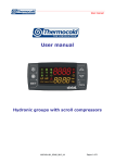
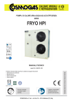
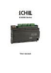
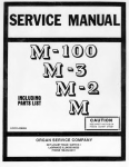
User manual User manual Multifunctional units MUIPROSUEL_REV01_0413_UK Pagina 1 di 18 User manual INDEX 1.1 Advanced electronics ............................................................................................................. 3 1.2 Display description ................................................................................................................. 3 1.2.1 Buttons description and their functions............................................................................. 5 2.1 On/Off of the unit..................................................................................................................... 7 2.2 Remote control of the unit...................................................................................................... 7 2.2.1 Controlling the unit remotely by means of free contacts .................................................. 7 2.2.2 Controlling the unit remotely by means of ModBus protocol ........................................... 8 3 Alarm display ............................................................................................................................. 9 3.1 Alarm reset .............................................................................................................................. 9 4 Set point display ...................................................................................................................... 10 4.1 Set point editing .................................................................................................................... 10 5 Configuration parameters ....................................................................................................... 10 5.1 How to edit user level parameters (Pr1) .............................................................................. 10 5.2 How to edit parameters value............................................................................................... 11 5.3 Parameters table ................................................................................................................... 12 6 Alarms ...................................................................................................................................... 17 7 Remote display ........................................................................................................................ 18 MUIPROSUEL_REV01_0413_UK Pagina 2 di 18 User manual 1.1 Advanced electronics The control logic, developed by Thermocold, allows to satisfy cooling and heating demand. In case of simultaneous heating and cooling demand, the unit exchanges the condensation and evaporation heat respectively with the cold circuit and the hot circuit of the plant. When the thermal load are not balanced, or one of the two is absent, the unit uses automatically a third heat source, which can be depending on the model, the air or the water. 1.2 Display description Through the LED display, you can monitor and change the status of the unit, using the 6 buttons positioned in the lower part of the keypad Available information on display: By pressing the UP and DOWN keys on the Home screen, you can view the following values: • "LP1": Display of pressure of the low pressure line; • "EIn": Displays the water temperature at the exchanger inlet air-conditioning; MUIPROSUEL_REV01_0413_UK Pagina 3 di 18 User manual • "Eout": Displays the temperature of the water leaving the exchanger of air-conditioning; • "Et": Displays the outside air temperature (only for air / water); • "Pcond": Display of pressure of the high pressure branch; “SIn”: Displays the water temperature at the exchanger inlet domestic hot water; “SOut”: Displays the temperature of the water leaving the exchanger of domestic hot water (if present); “COut”: Displays the temperature of the water leaving the exchanger of source side (only for water / water). In addition to the input buttons in the menus listed below, are also present in the home screen and buttons that allow you to activate the machine operation respectively in summer and winter operation. The display shows OnC when the unit is on and chiller, OnH when the unit is turned on in heat pump, OnR when the unit is only hot water production, OnCr with chiller unit more sanitary and Stby when the unit is key to OFF. Description of the icons on the display: MUIPROSUEL_REV01_0413_UK Pagina 4 di 18 User manual 1.2.1 Buttons description and their functions The controller is provided with six buttons to interact with user and installer parameters. Here below the description of the accessible operations through the buttons. Press and release in the main display: It allows you to visualize the chiller (label SETC) or heat pump (label SetH) set point Press and release 2 times in the main display: If the energy saving or dynamic set point is enabled for machines without storage, the icon Vset is lit and the display shows the work real set Press for 3 seconds and release in the main display: It allows you to edit the chiller / heat pump set point Press and release in the ALrM menu: It allows you to reset the alarm (if this alarm can be reset) from the menu ALrM Press and release: from the main display it allows you to show the values of the configured probes (temperature / pressure) in the upper display, and the corresponding label in the lower display. Press and release in the PrG menu: it allows to slide in the parameters folders (ST, CT, etc.) and in the parameters list. In parameter editing phase, it increases the value. Press and release: from the main display it allows you to show the values of the configured probes (temperature / pressure) in the upper display, and the corresponding label in the lower display. Press and release in the PrG menu: it allows to slide in the parameters folders (ST, CT, etc.) and in the parameters list. In parameter editing phase, it increases the value. MUIPROSUEL_REV01_0413_UK Pagina 5 di 18 User manual Press and release: It provides access to menu functions Press for 3 seconds and release: it allows you to adjust the watch in the provided models. Press and release in the PrG menu: it quits the parameter change. Press and release: it allows you to switch on the machine on heat pump or select standby mode Press and release: it allows you to switch on the machine on chiller or select standby mode Some controller functions are available through the multiple keys simultaneous pressure; following are the combinations accepted by the controller. + Simultaneous pressure of buttons for 3 seconds: it allows to access to parameters programming + Simultaneous pressure of buttons: 1. it allows to quit from parameters programming 2. the simultaneous extended pressure of the buttons active the manual defrost MUIPROSUEL_REV01_0413_UK Pagina 6 di 18 User manual 2.1 On/Off of the unit WARNING: Supply power to the unit at least 8 hours before the startup, penalty the annulment of the warranty. Pressing or for about three seconds it can switch on the machine in chiller or heat pump mode. During these 3 seconds, the selected mode led flashes. To change machine mode, for example to pass from chiller to heat pump mode, it must passing to the standby mode before. If the controller is on, the extended pressure on the button of the current mode (chiller or heat pump) forces the machine on standby. In standby mode, you can still to enter in menu to change the parameters. Alarm management is enabled also in standby mode; alarms that occur are equally shown. 2.2 Remote control of the unit It is possibile to control the unit remotely with two different methods: Free contacts on the user terminal (X); ModBus protocol on RS485 serial port master or slave; 2.2.1 Controlling the unit remotely by means of free contacts On the X user terminal there are four free terminals where you can connect any type of temperature control device able to provide a current pulse to close the relay for the unit activation. The terminals are those with the numbers 6, 20, 22B, 23 and 29, on the X user terminal (always refer to the wiring diagram included), this contact is generally a normally open contact. With these contacts you can enable remote On/Off, S/W change, wire plant side and domestetic hot water flow switches, and you can enable the “Only Recovery” function. You can enable the “Only Recovery” function by key only using the remote display. To enable the remote S/W changing you need modify SP9. On the same terminal are also available free contacts for external reporting of general alarm. MUIPROSUEL_REV01_0413_UK Pagina 7 di 18 User manual 2.2.2 Controlling the unit remotely by means of ModBus protocol On the control device installed on the unit, an input is available for serial connection on RS485 port with ModBus protocol, to use this type of connection please observe the wiring diagram below, observing a bus type connection, and avoiding to create stars. You can use the master and slave RS485 port, depending on the location of the instrument in the network. To connect to the devices to be controlled simply use two minimum cross-section of 0.5 mm2 plus screen, use the input GND only for communication problems. MUIPROSUEL_REV01_0413_UK Pagina 8 di 18 User manual 3 Alarm display Enter to the function menu: 1. Select “ALrM” function using 2. Press and release ; 3. The pressure on or or ; allows to show active alarms. Press the Menu key or wait the timeout, to exit to this visualization. 3.1 Alarm reset 1. Enter to the function menu; 2. Select the function “ALrM”; 3. Press ; lower display shows the alarm while the upper display shows the label rSt if the alarm is resettable, or NO if it isn’t. Using or you can slide and show all active alarms; 4. Press on the label rSt to reset alarm and pass to the next; 5. Press the Menu key or wait the timeout, to exit to this visualization. MUIPROSUEL_REV01_0413_UK Pagina 9 di 18 User manual 4 Set point display Pressing and releasing the button, it can see the setpoint value, SetC (set chiller) if the machine is on the chiller mode, or SetH (set heat pump) if the machine is on the heat pump mode. Pressing and releasing the button when the machine is on the standby mode, it is possible to display both set points. 4.1 Set point editing 1. Press the key at least for 3 sec; 2. The set point will display blinking; 3. To modify set point value, press 4. Press the and ; key, or wait the timeout to save the new value and to quit from programming; 5 Configuration parameters Controller parameters grouped in functional folders (CF = configuration, CO = compressor,…) with a specific label each. The generic group ALL contain all controller parameters. 5.1 How to edit user level parameters (Pr1) How to enter in “Pr1”: 1. Press and for some seconds; 2. Icons flash and upper display shows “ALL” (generic parameters group); MUIPROSUEL_REV01_0413_UK Pagina 10 di 18 User manual 3. Slide the parameters groups using and ; 4. Select the group that contains parameters to edit. Pressing the set button, you can enter in the parameters list of that group. Lower display shows parameter label and the upper its value. 5.2 How to edit parameters value 1. Enter in the parameters menu; 2. Select parameter; 3. Press the key to eneble the edit; 4. You can edit the value using 5. Press the or ; button to save the new value and to move to the next; 6. To exit, press the key, when you are in parameters viewing (not during the change with blinking value), or wait the timeout. NOTE: The new value is saved also, when you quit because of timeout without pressing the button. WARNING: you can change the CF (configuration parameters) group parameters values, when the machine is on standby mode or on remote OFF, only. You cannot change dF parameters if the unit is on defrost mode. MUIPROSUEL_REV01_0413_UK Pagina 11 di 18 User manual 5.3 Parameters table The parameters are grouped by macro-groups, as follows: ST SD ES FS SP Thermoregulation parameters Dynamic set point parameters Energy saving parameters Sanitary water parameters Remote S/W & Automatic Change Over Thermoregulation parameters Parameters ST1 ST4 Description Summer set point min max u.m. Risolution ST02 ST03 °C/°F dec/int Winter set point ST04 ST05 °C/°F Dec/ int min max u.m. Risolution Dynamic set point Parameters Description Sd1 Summer dynamic set point offset max -50.0 110.0 °C Dec Sd2 Winter dynamic set point offset max -50.0 110.0 °C Dec Sd3 Summer set external air temperature -50.0 110 °C Dec Sd4 Winter set external air temperature -50.0 110 °C Dec Sd5 Summer differential external air temperature -50.0 110.0 °C Dec Sd6 Winter differential external air temperature -50.0 110.0 °C Dec min max u.m. Risolution Energy Saving Parameters Description ES1 Time band 1 begin 0 23.50 Min 10 min ES2 Time band 1 end 0 23.50 Min 10 min ES3 Time band 2 begin ES2 23.50 Min 10 min ES4 Time band 2 end 0 23.50 Min 10 min ES5 Time band 3 begin ES4 23.50 Min 10 min MUIPROSUEL_REV01_0413_UK Pagina 12 di 18 User manual ES6 Time band 3 end 0 23.50 ES7 Monday 0 = No time band 1 = Time band 1 2 = Time band 2 3 = Time band 1 & 2 4 = Time band 3 5 = Time band 1 & 3 6 = Time band 2 & 3 7 = All time band Tuesday 0 = No time band 1 = Time band 1 2 = Time band 2 3 = Time band 1 & 2 4 = Time band 3 5 = Time band 1 & 3 6 = Time band 2 & 3 7 = All time band Wednesday 0 = No time band 1 = Time band 1 2 = Time band 2 3 = Time band 1 & 2 4 = Time band 3 5 = Time band 1 & 3 6 = Time band 2 & 3 7 = All time band Thursday 0 = No time band 1 = Time band 1 2 = Time band 2 3 = Time band 1 & 2 4 = Time band 3 5 = Time band 1 & 3 6 = Time band 2 & 3 7 = All time band Friday 0 = No time band 1 = Time band 1 2 = Time band 2 3 = Time band 1 & 2 4 = Time band 3 5 = Time band 1 & 3 6 = Time band 2 & 3 7 = All time band 0 7 0 7 0 7 0 7 0 7 ES8 ES9 ES10 ES11 MUIPROSUEL_REV01_0413_UK Min 10 min Pagina 13 di 18 User manual ES12 ES13 ES14 Saturday 0 = No time band 1 = Time band 1 2 = Time band 2 3 = Time band 1 & 2 4 = Time band 3 5 = Time band 1 & 3 6 = Time band 2 & 3 7 = All time band Sunday 0 = No time band 1 = Time band 1 2 = Time band 2 3 = Time band 1 & 2 4 = Time band 3 5 = Time band 1 & 3 6 = Time band 2 & 3 7 = All time band Summer increase set energy saving 0 7 0 7 -50.0 110.0 °C Dec ES15 Summer differential Energy saving 0.1 25.0 °C Dec ES16 Winter increase set energy saving -50.0 110.0 °C Dec ES17 Winter differential Energy saving 0.1 25.0 °C Dec Automatic on/off by time band ES18 Monday 0 = No time band 1 = Time band 1 2 = Time band 2 3 = Time band 1 & 2 4 = Time band 3 5 = Time band 1 & 3 6 = Time band 2 & 3 7 = All time band 0 MUIPROSUEL_REV01_0413_UK 7 Pagina 14 di 18 User manual ES19 ES20 ES21 ES22 ES23 Tuesday 0 = No time band 1 = Time band 1 2 = Time band 2 3 = Time band 1 & 2 4 = Time band 3 5 = Time band 1 & 3 6 = Time band 2 & 3 7 = All time band Wednesday 0 = No time band 1 = Time band 1 2 = Time band 2 3 = Time band 1 & 2 4 = Time band 3 5 = Time band 1 & 3 6 = Time band 2 & 3 7 = All time band Thursday 0 = No time band 1 = Time band 1 2 = Time band 2 3 = Time band 1 & 2 4 = Time band 3 5 = Time band 1 & 3 6 = Time band 2 & 3 7 = All time band Friday 0 = No time band 1 = Time band 1 2 = Time band 2 3 = Time band 1 & 2 4 = Time band 3 5 = Time band 1 & 3 6 = Time band 2 & 3 7 = All time band Saturday 0 = No time band 1 = Time band 1 2 = Time band 2 3 = Time band 1 & 2 4 = Time band 3 5 = Time band 1 & 3 6 = Time band 2 & 3 7 = All time band 0 7 0 7 0 7 0 7 0 7 MUIPROSUEL_REV01_0413_UK Pagina 15 di 18 User manual ES24 Parameters FS1 FS2 FS3 0 7 Sunday 0 = No time band 1 = Time band 1 2 = Time band 2 3 = Time band 1 & 2 4 = Time band 3 5 = Time band 1 & 3 6 = Time band 2 & 3 7 = All time band Sanitary water parameters Description SW enabling 0 = Disable 2 = Enable Priorità di funzionamento 0 = ACS 1 = Climatizzazione SW set point min max 0 2 0 1 35.0 55.0 u.m. Risolution °C Dec. Remote S/W & Automatic Change Over Parameters SP9 SP10 SP11 Description S/W Change 0 = By Keypad 1 = By Digital Input 2 = By Analogic Input Set Automatic Change Over Differential Automatic Change Over min max 0 2 -50.0 0.1 MUIPROSUEL_REV01_0413_UK u.m. Risolution 110.0 °C Dec. 25.0 °C Dec. Pagina 16 di 18 User manual 6 Alarms The controller is able to identify all alarms that may damage the normal operation of the machine. For each alarm code, the controller performs a given action. Below is a table with the alarm codes. Alarm code AP”x” b1HP b1LP b1hP b1IP AFFC AEFL AHFL APFL ACFL C1tr b1tF AtE1 AtC1 b1dF C1Mn AEP1 ACP1 C1dt OPC1 AEht ACF”x” APS ALc1 Description Failure on probe “x” High pressure switch alarm Low pressure switch alarm High pressure alarm from transducer Low pressure alarm from transducer Antifreeze alarm Plant side flow alarm Sanitary water flow alarm Solar panel flow alarm Source side flow alarm Compressor 1 overload Condenser fan overload Evaporator pump overload Condenser pump overload Defrost alarm Compressor 1 maintenance request Evaporator pump maintenance request Condenser pump maintenance request High discharge temperature compressor 1 Oil compressor 1 pressure switch High temperature evaporator water inlet Configuration alarm “x” Phases sequence alarm Generic alarm 1 MUIPROSUEL_REV01_0413_UK Pagina 17 di 18 User manual 7 Remote display The remote terminal is connected directly to the controller connectors designed for the remote keypad, paying particular attention to the polarity of the connections. Wrong wiring may cause serious damage to the keyboard or controller. MUIPROSUEL_REV01_0413_UK Pagina 18 di 18