1
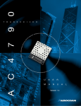
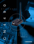
ConnexLink
User’s Manual
Version 1.0
Document Information
Copyright
Information
Copyright © 2001 AEROCOMM, Inc. All rights reserved.
The information contained in this manual and the accompanying
software programs are copyrighted and all rights are reserved by
AEROCOMM, Inc. AEROCOMM, Inc. reserves the right to make
periodic modifications of this product without obligation to notify
any person or entity of such revision. Copying, duplicating, selling, or otherwise
distributing any part of this product without the prior consent of an authorized
representative of AEROCOMM, Inc. is prohibited.
All brands and product names in this publication are registered
trademarks or trademarks o f their respective holders.
This material is preliminary
Information furnished by AEROCOMM in this specification is believed to be accurate. Devices sold
by AEROCOMM are covered by the warranty and patent indemnification provisions appearing in its
Terms of Sale only. AEROCOMM makes no warranty, express, statutory, and implied or by
description, regarding the information set forth herein. AEROCOMM reserves the right to change
specifications at any time and without notice.
AEROCOMM’s products are intended for use in normal commercial applications. Applications
requiring extended temperature range or unusual environmental requirements such as military,
medical life-support or life-sustaining equipment are specifically not recommended without
additional testing for such application.
Limited Warranty
For a period of one (1) year from the date of purchase, A EROCOMM warrants the transceiver
against defects in materials and workmanship. A EROCOMM will not honor this warranty (and this
warranty will be automatically void) if there has been any:
(1) Tampering, signs of tampering, or opening the tranceiver’s case.
(2) Use of AC power adapters and cables other than those originally supplied with the
transceivers.
(3) Repair or attempt to repair by anyone other than an A EROCOMM authorized
technician.
This warranty does not cover and A EROCOMM will not be liable for, any damage or failure caused
by misuse, abuse, acts of God, accidents, electrical irregularity, or other causes beyond
A EROCOMM's control, or claim by other than the original purchaser.
6/3/2002
2
FCC Information
FCC Notice
WARNING: This device complies with Part 15 of the FCC Rules. Operation is subject to
the following two conditions: (1) This device may not cause harmful
interference and (2) This device must accept any interference received,
including interference that may cause undesired operation.
RF Exposure (For 200mW units only: Part Numbers CL200 & CL200A)
WARNING: To satisfy FCC RF exposure requirements for mobile and base station
transmitting devices, a separation distance of 32cm or more should be
maintained between the antenna of this device and persons during
operation. To ensure compliance, operations at closer than this distance is
not recommended.
The preceding statement must be included as a CAUTION statement in
manuals for OEM products to alert users on FCC RF Exposure compliance.
6/3/2002
3
Table of Contents
1.
Overview.......................................................................................................................5
1.1
ConnexLink Definitions............................................................................................5
1.2
ConnexLink Configuration Utility Software ................................................................6
1.2.1
Installation......................................................................................................6
1.2.2
Software Definitions ........................................................................................6
1.2.3
Programming..................................................................................................7
1.3
Troubleshooting......................................................................................................8
Figures
Figure 1 - Multiple Networks Of ConnexLink Units.....................................................................5
Figure 2 - ConnexLink Bottom View .........................................................................................5
6/3/2002
4
ConnexLink User’s Manual
1. Overview
The ConnexLink products provide a wireless RS232 connection between different devices. Each
ConnexLink unit can be programmed as a Server or a Client, allowing for the creation of a two
device or multiple device wireless network. In addition, multiple networks can be created by
programming each network of ConnexLink units with unique Channel Number and System ID
combinations. See Figure 1 below. To create a wireless network, simply program one of the
units as a Server and the other units as Clients.
Figure 1 - Multiple Networks Of ConnexLink Units
Example: Channel Number = 13
System ID = 001002003004005006007008
1.1
Example: Channel Number = 25
System ID = 012023034045056067078089
ConnexLink Definitions
1.
Pwr: Red LED indicates power is connected to the unit.
2.
Link: Green LED indicates the Client unit(s) and Server unit are in range of one another.
3.
Rx: Red LED indicates when a ConnexLink unit is receiving data.
4.
Tx: Green LED indicates when a ConnexLink unit is sending data.
5.
Reset Button: Push-button switch located closest to the power connector and serial
cable on the bottom of the unit. See Figure 2 below.
6.
Program Button: Push-button switch located next to the Reset Button on the bottom of
the unit. See Figure 2 below.
Figure 2 - ConnexLink Bottom View
6/3/2002
5
ConnexLink User’s Manual
1.2
ConnexLink Configuration Utility Software
The software CD included with your ConnexLink units provides a utility for changing the settings
on each unit. The software is compatible with Microsoft® Windows 95, 98, 2000, Me, and NT.
1.2.1 Installation
Follow the procedure below to install the ConnexLink Configuration Utility software.
1.
2.
3.
4.
5.
6.
7.
8.
Insert the CD into the desired CD-ROM drive on your computer.
Click on the Windows Start menu and select Run.
Select Browse and then select the appropriate CD-ROM drive letter.
Select the file named Setup.exe and then select Open.
Select OK to begin the installation.
When prompted, accept the default directory or change to the desired directory where the
program files will be installed.
Select Installation to begin copying files.
When finished, a window will be displayed indicating a successful installation. Select OK.
1.2.2 Software Definitions
1.2.2.1 ConnexLink Settings Window
1.
Client/Server: Designates ConnexLink type. In each network, there must be only one
Server. All other ConnexLink units must be programmed as Clients. The number of
Clients in the network is not limited; however, if performance diminishes, consider
additional RF Networks.
2.
Baud Rate: This defines the Serial baud rate between the ConnexLink unit and the host
device, such as a PC. The RF transmission rate is fixed.
3.
Maximum Transmit Attempts: For Point-to-Point networks only. This value represents
the maximum number of times a data packet can be sent by the ConnexLink units. The
default value is 10 attempts. If communication is lost and the Client’s Link LED is on, try
increasing this value in small increments until communication is reestablished. The valid
range of values for this field is 1 to 255.
4.
Broadcast Attempts: For Point-to-Multipoint networks only. This value represents the
number of times a data packet will be sent by the Server ConnexLink unit. The default
value is 4 attempts. If communication is lost and the Clients’ Link LED is on, try
increasing this value in small increments until communication is reestablished. The valid
range of values for this field is 1 to 255.
5.
Channel Number: A number that designates an independent network of ConnexLink
units. Up to 77 independent networks can created. The valid range of values for this
field is 0 to 76.
6.
System Identification: A sequence of eight numbers that provide added security to
each independent network of ConnexLink units. The valid range of values for each of the
eight numbers is 0 to 255.
Important Note: For a network of ConnexLink units to communicate with
each other, all ConnexLink units must have identical Channel Numbers and
System IDs. If additional networks are created, each network must use
different Channel Numbers and System IDs so that existing networks are
not interfered with.
6/3/2002
6
ConnexLink User’s Manual
1.2.2.2 Computer Settings Window
1.
Port: Serial communications port connected to the ConnexLink unit.
2.
Baud Rate: Serial baud rate of the PC COM Port.
3.
System Config: Type of ConnexLink network to be configured. Valid choices are Pointto-Point (one Server and one Client) or Point-to-Multipoint (one Server and multiple
Clients).
1.2.3 Programming
Each ConnexLink unit must be set up in Program Mode before any settings can be changed.
This is accomplished with the following procedure:
1.
Connect a ConnexLink unit to a serial communications port on your computer.
2.
Connect the power supply to the ConnexLink unit. Make sure the Pwr LED is on.
3.
Start the ConnexLink Configuration Utility.
4.
Select Settings to display the Computer Settings window.
5.
a.
Select the COM Port that is connected to the ConnexLink unit.
b.
Select the baud rate of the ConnexLink unit. All ConnexLink units are shipped
with a default baud rate of 57600. If the baud rate of the ConnexLink unit is
changed as described below in Section 1.2.3.1 Changing ConnexLink
Settings, then this setting must be set to the same baud rate to allow proper
programming of the units.
c.
Select the system configuration for the ConnexLink network, Point-to-Point (one
Server and one Client) or Point-to-Multipoint (one Server and multiple Clients).
d.
Select OK.
Press and hold the Program Button located on the bottom the unit. While holding the
Program Button, press the Reset Button also located on the bottom of the unit.
Release the Reset Button first, followed by releasing the Program Button. The
ConnexLink unit is now in program mode. See Figure 2. ConnexLink Bottom View for
location of buttons.
1.2.3.1 Changing ConnexLink Settings
After the ConnexLink unit has been set up in Program Mode, any settings can be changed and
saved in the unit. This is accomplished with the following procedure:
1.
Select Read Radio to display the current settings of the ConnexLink unit.
2.
Change desired settings.
3.
After all changes have been made, select Write Radio to save the changes.
4.
a.
A message window will be displayed – Press and hold the Program Button.
b.
While holding the Program Button, select OK.
c.
Wait for a message window to be displayed, confirming the saved changes.
d.
Release the Program Button and select OK.
Press the Reset Button, located on the bottom of the unit, after all changes have been
saved. This will set the ConnexLink unit to its normal mode of operation.
6/3/2002
7
ConnexLink User’s Manual
1.3
Troubleshooting
Problem
Solution
Read Radio displays error message: “Radio
not responding.”
Make sure the ConnexLink unit is in Program
Mode. See Section 1.2.3 Programming.
Write Radio displays error message: “Radio
not responding.”
Make sure the ConnexLink unit is in Program
Mode and the Program button is depressed
until message is displayed to release the
button. See Section 1.2.3 Programming.
Client’s Link LED does not come on.
1.
Make sure Server ConnexLink unit is
connected to power.
2.
Press the Reset button or disconnect and
reconnect power.
1.
Make sure the ConnexLink unit(s) is
connected to the correct COM Port.
2.
Make sure the baud rate of the ConnexLink
unit(s) is equal to the baud rate of the
device it is connected to.
3.
Try increasing the Maximum Transmit
Attempts (for Clients) and/or Broadcast
Attempts (for Servers) values in small
increments until communication is
established.
Link LED is on, but data does not get
transmitted or received.
If these troubleshooting tips do not resolve the problem, please call our toll free technical support
number at (800) 492-2320, extension 201. Technical support hours are Monday through Friday,
8:00 am to 5:00 pm Central Standard Time.
6/3/2002
8