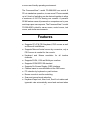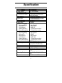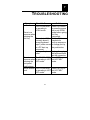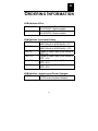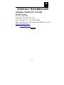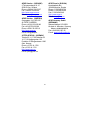
1
8-Port KVM SWITCH with On-Screen Display MODEL FO-098-8080 1 PREVENTING RADIO & TV INTERFERENCE This equipment generates, uses, and can radiate radio frequency energy and if not installed and used in accordance with the instructions manual, may cause interference to radio communications. It has been tested and found to comply with the limits for a Class A computing device pursuant to Subpart J of Part 15 of FCC Rules, which are designed to provide reasonable protection against such interference when operated in a commercial environment. Operation of this equipment in a residential area is likely to cause interference in which case the user at his own expense will be required to take whatever measures may be required to correct the interference. LIMITED WARRANTY IN NO EVENT SHALL THE DIRECT VENDOR’S LIABILITY EXCEED THE PRICE PAID FOR THE PRODUCT FROM DIRECT, INDIRECT, SPECIAL, INCIDENTAL OR CONSEQUENTIAL DAMAGES RESULTING FROM THE USE OF THE PRODUCT OR ITS DOCUMENTATION. 2 TABLE OF C ONTENTS hapter 1 : Introduction 1 C General Information ................................................... 1 Features..................................................................... 2 Package Contents...................................................... 4 Specifications............................................................. 5 Connectors and Cables ............................................. 6 Front & Rear Panel Description ................................. 9 hapter 2 : Installation 10 C Operating Environment ............................................ 10 Installation................................................................ 10 Installing One FO-098-8080..................................... 10 Installing Multiple FO-098-8080 ............................... 11 hapter 3 : Operation 14 C Front-Panel Push Buttons ........................................ 14 1 Keyboard Hot Keys .................................................. 15 On Screen Display(OSD) Interface .......................... 16 C hapter 4 : Osd Quick Sarting Guide ...................................................................................... 19 hapter 5 : Dip Switch Setting C ...................................................................................... 22 hapter 6 : Leds Display 23 C hapter 7 : Trouble Shooting C ...................................................................................... 24 A ppendix A : Order Information ...................................................................................... 26 A ppendix B : Contact Information ...................................................................................... 28 2 1 I NTRODUCTION General Information The Signamax Connectivity Systems CommandView model FO-098-8080 is a Keyboard/Video/Mouse (KVM) controller that provides the easiest and most cost-effective way for one user to access multiple computers. Switching from one computer to another is easily done by pressing Hot Keys or push buttons, or via the most convenient way, the On-Screen Display (OSD) menu. Because the CommandView model FO-098-8080 is an intelligent controller, it can intercept and process Hot Keys directly from the keyboard. Therefore, NO extra software is required to be installed, so there are no software incompatibility problems to worry about. The Signamax CommandView model FO-098-8080 also incorporates a mouse conversion feature, which eliminates the redundancy and inconvenience of needing both a PS2 and a Microsoft serial mouse to be attached to the console. Moreover, the innovative OSD interface offers the operator 1 a more user-friendly operating environment. The CommandView model FO-098-8080 can control 8 PCs in standalone operation; in case more PCs are needed, up to 8 levels of switching can be chained together to allow a maximum of 64 PCs sharing one console. A powerful SCAN feature scans all powered-on computers one by one and stops upon user requests. The CommandView model FO-098-8080 is ideal for server rooms, control rooms, test rooms, and similar environments. Features ♦ Supports PC-AT & PS/2 keyboard, PS/2 mouse as well as Microsoft IntelliMouse. ♦ Supports Microsoft serial mouse by conversion; only a PS/2 mouse is needed for the console. ♦ Keyboard and Mouse emulation for all inactive channels. ♦ ♦ ♦ ♦ ♦ ♦ ♦ ♦ Supports SVGA, VGA and Multisync monitors. Supports VESA DDC1/2B standard. Supports On-Screen Display (OSD) interface. Channel name is user-definable via the OSD menu. PC selection by keyboard or push buttons. Buzzer sounds to confirm switching. Scan and manual mode selection. Keyboard Caps Lock, Num.Lock, Scroll Lock states and typematic rate automatically saved and restored when 2 switching among computers. ♦ Scan mode automatically switches through powered-on computers; scan rate is user-selectable via the OSD menu. ♦ Designed as a desktop and 19” rackmount unit. ♦ Supports chaining ports; allows up to 8 levels, with a maximum of 64 PCs able to share one console. ♦ Saves space, energy and the cost of duplicated equipment. 3 Package Contents CommandView Model FO-098-8080 KVM Switch x1 DB37 male to male Chain Cable x1 User’s Manual x1 AC Power Adapter x1 Rack mount accessories x2 Rubber foot pad x4 4 Specification Model Power supply Number of PC port PC selection method Scan interval Signal type VGA bandwidth Chain ability Console connectors Keyboard(PS/2) Mouse(PS/2) VGA Monitor Stereo(Speaker) Mono(Microphone) PC port connectors Keyboard(PS/2) Mouse(AT) Mouse(PS/2) VGA Monitor Stereo(Speaker) Mono(Microphone) Chain connector Cable length Enclosure Power Weight Dimension Operating Environment Emission FO-098-8080 AC 16V 1000mA 8 Push-button/Keyboard Hot keys/OSD menu 5/10/20/40 seconds VGA/Keyboard/Mouse/Stere o Audio/Microphone 200 MHz 8 levels 1 Mini-DIN6/F 1 Mini-DIN6/F 1 HDB15/F 1 3.5mm Stereo socket 1 3.5mm Mono socket 1 Mini-DIN6/F 1 DB9/F 1 Mini-Din6/F 1 HDB15/M 1 3.5mm Stereo socket 1 3.5mm Mono socket DB37 female PC to CPUSW: 35m Console to CPUSW: 50m Metal AC 16V 1000mA 8.36 lbs.(3800g) 17.5x7.9x3.5 in.(440*200*88 mm) 32-131°F(0-55°C), 0%-90% RH FCC Class A, CE Mark 5 Connectors and Cables Console Connectors Four different types of console connectors are built on the rear panel for connection to the keyboard, monitor, and mouse. • • • • PS/2 Keyboard—6-pin mini DIN, female. PS/2 Mouse—6-pin mini DIN, female VGA Monitor—HDB15, female Stereo/Mono—3.5mm audio socket PC Port Connectors Eight groups of connectors are built on the rear panel for connection to PCs using standard keyboard, monitor and mouse cables. Please refer to “Specification” in page 1000 for detail of each model’s PC port connectors. RECOMMENDED CONNECTING CABLES Signamax Hydra Switch Extension: Cable For PC-To-KVM Part Number C-65T-6/10 (6 or 10 foot lengths) PS/2 Multicoax Extension Cable 6 Connectors • Keyboard: PS/2 Mini-DIN 6-Pin Male-Female • Mouse: PS/2 Mini-DIN 6-Pin Male-Female • Video: High-Density 15-Pin Male-Female Function This cable extends the Keyboard / Monitor / Mouse connection to the KVM Switch or a CPU. This single zip cable avoids the typical unsightly snarl and tangle of multiple cables. Its 50 Micron gold–plated connectors combine with labeled, color-coded connector molds for secure, easy, high-quality connections. The video cable has a ferrite core for the highest video quality. Signamax Hydra Cable Switch-To-CPU Connection: For Part Number C-69T-6/10/15/25 PS/2 KVM Switch to CPU Cable • 6, 10, 15, or 25 foot lengths are available Connectors • Keyboard: PS/2 Mini-DIN 6-Pin Male-Male • Mouse: PS/2 Mini-DIN 6-Pin Male-Male • Video: High-Density 15-Pin Male-Female 7 KVM Function This cable extends the Keyboard / Monitor / Mouse connection from the KVM Switch to a CPU. This single zip cable avoids the typical unsightly snarl and tangle of multiple cables. Its 50-micron gold–plated connectors combine with labeled, color-coded connector molds for secure, easy, high-quality connections. The video cable also has a ferrite core for the highest video quality. 8 Front & Rear Panel Description Front Panel Rear Panel 9 2 I NSTALLATION Operating Environment The Signamax CommandView™ KVM Switch must be installed and operated within the limits of the specified operating temperatures and humidity (see previous section under Specifications). Do not place objects on top of the unit. Do not obstruct any vents at the sides of the unit. Do not position the unit near any heating source such as a heater, radiator, or direct exposure to the sun. Prevent entry of water and moisture into the unit. If necessary, use a dehumidifier to reduce humidity. Installation Please make sure that all the PCs are turned off before connecting or disconnecting cables to the Signamax CommandView FO-098-8080. Installing One FO-098-8080 • Set the bank address to 0, the master bank. (please refer 10 to “DIP Switch settings” chapter) • Connect the console (keyboard, mouse, monitor) • Connect each PC using the appropriate cable for PC side to the FO-098-8080 PC port. • Connect the AC power adapter to the FO-098-8080. • Power on the FO-098-8080, then turn on the PCs. Installing Multiple FO-098-8080 KVM Switches • Set one FO-098-8080 bank address to 0, the master bank. • Set other FO-098-8080 bank address to 1-7, the slave banks. You may choose whatever number you like, as long as the number is between 1-7 and each FO-098-8080 has a different bank address. • Using the DB37 chain cable, connect from the CHAIN OUT port of master bank to the CHAIN IN port of the first slave bank. Then, using another chain cable, connect from the CHAIN OUT port of the first slave bank to the CHAIN IN port of second slave bank, and so forth. • Connect the console (keyboard, mouse, monitor) to the MASTER FO-098-8080 console port. • Connect each PC using the appropriate cable for PC side to the FO-098-8080 PC port. • • Connect AC power adapter to each FO-098-8080. Power on the slave banks first, then the master bank, then, finally, turn on the PCs. 11 NOTE: When the FO-098-8080s are configured as a chain operation, only the front panel push button of the MASTER bank is functional. 12 13 3 O PERATION You can access any PC by the push buttons on the front panel or Hot Keys on the console keyboard, or the most convenient way, the OSD menu. For a quick starting guide to the OSD menu, please refer to the next chapter. Front Panel Push Buttons Select PC by the front panel push buttons: There are two different modes of push button functions corresponding to the setting of the rear panel MODE DIP SW. With the MODE DIP SW set to ON: • The left button is BANK+. If the FO-098-8080 is in chained operation, pushing this button will advance to the next available bank in the cycle. • The right button is CH+. Push this button to advance to the next powered-on PC in the cycle, and it will not cross the bank boundary. With the MODE DIP SW set to OFF: • The left button is CH-. Push this button to go back to the previous powered-on PC in the cycle, and it will cross the 14 bank boundary. • The right button is CH+. Push this button to advance to the next powered-on PC in the cycle, and it will cross the bank boundary. If the CH+ button is pushed and held over 1 second, the SCAN LED will be lit, and the buzzer will beep twice; now the FO-098-8080 KVM Switch is in SCAN mode. To return to NORMAL mode, either push the CH+ button on the front panel and release within 1 second, or press the SPACE bar on the keyboard. Keyboard Hot Keys Select a PC by the keyboard hot keys: Press the Scroll Lock key twice within 1 second to enter Hot Key mode. In Hot Key mode, the keyboard status LED will flash and wait further input from the user; after the user’s action is completed, press the ESC key to leave Hot Key mode. Note: Pressing a key means to depress the key then release it immediately; if the input is correct, the buzzer will beep to confirm it. • To switch to the next powered-on PC: → Press the ‘RIGHT SHIFT’ key. • To switch to the previous powered-on PC: → Press the ‘LEFT SHIFT’ key. • To select a BANK directly: 15 → Press the ‘b’ key, followed by a 1-digit number. (e.g., b0 will switch to BANK0, b2 will switch to BANK2) • To select a PC directly: → Press the ‘c’ key followed by a 2-digit number. (e.g., c01 will switch to PC01, c05 will switch to PC05) • To start SCAN mode: → Press the ‘s’ key; the FO-098-8080 will leave Hot Key mode and enter the SCAN mode. On Screen Display (OSD) Interface Select a PC by the OSD menu: Press the Scroll Lock key twice within 1 second to enter Hot Key mode. In Hot Key mode, press the SPACE bar to call up the OSD menu. EDIT AREA BANK 0 01 12345678 02 03 04 05 06 07 08 CPU SWITCH MENU CURSOR UP CURSOR DN PREV. BANK NEXT BANK INS RENAME ENTER SWITCH ESC EXIT OSD F1 TIME EDIT F2 SCAN MODE 16 POWER ON SCAN INTERVAL 5SEC 10SEC 20SEC 40SEC The OSD menu is divided into 2 edit sections, called EDIT AREA and SCAN INTERVAL, and a MENU section for on-line help. The following are descriptions of each section. EDIT AREA ♦ When the “EDIT AREA” is blinking, it indicates that this area is selected and you can edit or use this area. ♦ The “BANK” indicates the current BANK location. You can use the LEFT/RIGHT arrow key to switch to other banks if those banks are available. ♦ The “ ” symbol represents the cursor, indicating which PC is currently selected. You can use the UP/DOWN arrow key to move the cursor to the desired location. ♦ 01~08: indicates the PC number. ♦ The area behind the PC number is used to edit/display the name of the PC; the maximum length of the PC name is 8 characters. ♦ : This symbol indicates that this PC is powered on. ♦ Press INS key to edit the PC name pointed by . A square cursor will show up indicating it is under edit mode; after editing is completed, press the ENTER 17 key to save the edited name and leave edit mode. ♦ While not in edit mode, pressing the ENTER key will switch to the PC corresponding to the setting of BANK number and PC number, and exit to the NORMAL operation. Or, press the ESC key without switching to the other PC and quit. ♦ Pressing the F2 key will exit OSD MENU and start SCAN operation. NOTE: Only PCs that are powered on can be switched. SCAN INTERVAL ♦ While the EDIT AREA is active, press the F1 key to switch to this area, and the “SCAN INTERVAL” will blink; then you can use the LEFT/RIGHT arrow keys to select the desired scan interval. After the selection is made, press the ENTER key to return to the EDIT AREA. NOTE: Please pause 1 second between each switching operation if you are making successive switching changes, otherwise sometimes there will be no response due to the delay of the keyboard and mouse reset. 18 4 OSD Q UICK S TARTING G UIDE How to call up the OSD MENU: (1) To call up the OSD MENU, press the Scroll Lock key twice rapidly (within 1 second), and press the SPACE key. How to edit the PC name: (1) Call up the OSD MENU. (2) Make sure that “EDIT AREA” is blinking and “SCAN (3) (4) (5) (6) INTERVAL” is not blinking. Use the Left/Right arrow key to select BANK. Use the Up/ Down arrow key to move to the PC that you’d like to edit. Press the INS key to enter edit mode and start editing the PC name. Press the ENTER key to save after editing. How to select the SCAN TIME: (1) Call up the OSD MENU. (2) Press the F1 key and the “SCAN INTERVAL” field starts blinking. “EDIT AREA” stops blinking. 19 (3) Use the Left/Right arrow key to select SCAN TIME. (4) After selecting SCAN TIME, press the ENTER key to return to the EDIT AREA and save the SCAN TIME. How to use the OSD MENU to switch to the desired PC: (1) Call up the OSD MENU. (2) Make sure “EDIT AREA” is blinking, “SCAN INTERVAL” is not blinking, and the unit is not in PC name editing mode. (3) Use the Left/Right arrow key to select BANK. (4) Use the Up/Down arrow key to move to the PC that you’d like to switch to. (5) Press the ENTER key to switch to the desired PC and exit the OSD MENU. NOTE: Only PCs that are powered on can be switched. How to use the OSD MENU to trigger the SCAN MODE: (1) Call up the OSD MENU. (2) Select SCAN TIME if necessary. (3) Make sure “EDIT AREA” is blinking. “SCAN INTERVAL” is not blinking and not in PC name editing mode. (4) Press the F2 key to trigger the SCAN MODE and exit the OSD MENU. How to exit the OSD MENU without switching to another PC: (1) The OSD MENU is already called up. 20 (2) Make sure “EDIT AREA” is blinking, “SCAN INTERVAL” is not blinking, and the unit is not in PC name editing mode. (3) Press the ESC key to exit the OSD MENU without switching to another PC. 5 D IP S WITCH S ETTINGS DIP SWITCHES 1-3 are used to set the Bank Address: 1 ON OFF ON OFF ON OFF ON OFF DIP Switch Number 2 3 ON ON BANK 0 ON ON BANK 1 OFF ON BANK 2 OFF ON BANK 3 ON OFF BANK 4 ON OFF BANK 5 OFF OFF BANK 6 OFF OFF BANK 7 21 Master Slave Slave Slave Slave Slave Slave Slave DIP SWITCH 4 is used to set the Front Panel Push Button Mode 6 L ED D ISPLAY BANK LED: For the master bank, BANK LED displays the selected bank number. For the slave banks, BANK LED displays the bank address of the bank. CHANNEL LED: For the master bank, CHANNEL LED displays the selected PC number. For the slave banks, CHANNEL LED is blank. SCAN LED: Indicates the unit is in SCAN mode. 22 23 7 T ROUBLESHOOTING Symptom Possible Causes Solution The FO-098-8080 Press CH+ button or press the space is operating in bar to exit SCAN SCAN mode. There is no mode before giving response when Hot Key pressing the commands. Hot Key. Wait for PC to The selected PC complete its currently doesn’t boot-up sequence accept keyboard input. (often occurs or change port by the push-button. in a PC boot-up sequence) Improper keyboard Unplug, then plug reset. the keyboard back into the connector. The FO-098-8080 Press ESC key to There is no response when is operating in HOT exit HOT KEY mode. KEY mode. pressing the front panel push buttons. Mouse doesn’t The FO-098-8080 Press ESC key to work. is operating in HOT exit HOT KEY mode. KEY mode. 24 Improper reset of the FO-098-8080. The CPU switch doesn’t work at all. Incorrect bank address setting. 25 Turn all PCs off, then turn off the CPU switch; wait for 3 seconds, turn on the CPU switch first, then turn all PCs on. Set correct bank address. A O RDERING I NFORMATION KVM Switches:8-Port FO-098-8080 Command View 8-Port KVM Switch 110V-AT&PS/2; Rackmountable FO-098-8080I Command View 8-Port KVM Switch 110V-AT&PS/2; Rackmountable KVM Switches: Associated Cables C-65-T-6 Plugged-In Hydra Cable (Keyboard, Video & Mouse to KVM Switch)—6 ft. C-65-T-10 Plugged-In Hydra Cable (Keyboard, Video & Mouse to KVM Switch)—10 ft. C-69-T-6 Plugged-In Hydra Cable (KVM Switch to CPU)---6 ft. C-69-T-10 Plugged-In Hydra Cable (KVM Switch to CPU)---10 ft. C-69-T-20 Plugged-In Hydra Cable (KVM Switch to CPU)---20 ft. C-69-T-30 Plugged-In Hydra Cable (KVM Switch to CPU)---30 ft. KVM Switches---Adapters and Gender Changers G292T-1 AT(5-pin DIN female) to PS/2 (6-pin Mini-DIN male) Keyboard Adapter 27 B C ONTACT I NFORMATION SIGNAMAX CONNECTIVITY SYSTEMS An AESP Company 1810 N.E. 144th Street. North Miami, Florida 33181, U.S.A. Phone: 305-944-7710 Fax: 305-652-8489 Sales: 800-446-2377 Tech.Support: 800-446-2377, ext. 201 Http:\\www.signamax.com E-mail: [email protected] EUROPE 28 AESP Ukraine. (UKRAINE) 2 Timiryazevskaya St. 47 252014 Kiev, Ukraine Phone: +380 44 296.53.57 Fax: +380 44 294.88.60 Http:\\www.aesp.com.ua E-mail: [email protected] AESP Russia. (RUSSIA) Kronshtadtsky Blv. 125499 Moscow, Russia Phone:+7 095-456-0704 Phone:+7 095-456-0344 Fax:+7 095-454-3040 Http:\\www.aesp.ru E-mail: [email protected] AESP Sweden. (SWEDEN) Grevegatan 19-21 SE-815 40 TIERP. SWEDEN Phone:+46-(0)-293-228 88 Fax:+46-(0)-293-228 89 Phone:+49-81-35-9303-0 Http:\\www.aesp.se E-mail: [email protected] AESP Germany GmbH (GERMANY) Weisserfelderstr.2 D-85551 Kircheim b. München, Germany Phone:+49-89-901-097-0 Fax:+49-89-901-097-22 E-mail: [email protected] JOTEC AESP AS. (NORWAY) Telefon 23 14 17 00 Ordrefax 23 14 17 10 Karihaugveien 102 Postboks 50 Ellingsrudasen 1006 Oslo, Norway Phone:+47-23-14-1700 Fax:+47-23-14-1710 Http:\\www.jotec.no E-mail: [email protected] 29