1
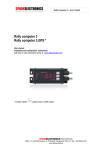
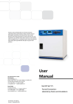
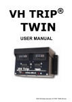
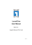
USER MANUAL
V1.1
INDEX
1.
2.
3.
4.
5.
6.
7.
8.
9.
Introduction .......................................................... Erreur ! Signet non défini.
ETRIP® Installation:...................................................................................... 4
a. Probes Installation: ..................................................................................... 4
b. Standard Probe installation : ................................. Erreur ! Signet non défini.
c. Cable driven universal probe installation : ............... Erreur ! Signet non défini.
d. Car Installation: .................................................. Erreur ! Signet non défini.
e. ETRIP® Connections: ........................................... Erreur ! Signet non défini.
f. ETRIP® Test: ............................................................................................. 6
Functionalities ....................................................... Erreur ! Signet non défini.
Tripmeter Mode ............................................................................................ 8
a. Probe choice ....................................................... Erreur ! Signet non défini.
b. Calibration .......................................................... Erreur ! Signet non défini.
c. Zero Reset ................................................................................................. 9
d. Display modifications .................................................................................. 9
e. Display accuracy ........................................................................................ 9
f. Freeze................................................................ Erreur ! Signet non défini.
g. Forward or Rewind ............................................... Erreur ! Signet non défini.
Average Speed Mode................................................................................... 10
a. Memory reset ........................................................................................... 10
b. Setting up start average speed target ......................................................... 10
c. Setting up next average speed target .......................................................... 10
d. Chosing stage first average speed target ..................................................... 11
e. Starting Average Speed Function in Automatic Mode ..................................... 11
f. Average speed Zero reset (Start) ................................................................ 11
g. Switching between manual and automatic modes .......................................... 11
h. Manual change to the average speed target being used ................................. 12
i. Average Speed change .............................................................................. 12
La Solution Mode ........................................................................................ 12
a. Display accuracy ...................................................................................... 12
Remote control ...................................................... Erreur ! Signet non défini.
LED Remote Display .................................................................................... 13
Technical Specifications (subjet to changes) :................................................ 13
2
1. Introduction
ETRIP© is the result of many years of research and first hand regularity rally experience. It has
been designed with both professional and novice crews in mind, using the best technology
available and ensuring ultimate accuracy and reliability in a very ergonomic design.
More than a simple Tripmaster, ETRIP© is a small revolution in the world of rally navigation
instrumentation which will quickly become a key member of you crew on stages.
Keys:
1. Partial Distance
2. Total Distance
3. Average Speed Target
4. Average to be changed Display Selection
5. Numeric pad
6. Zero Reset
7. Screen Freeze
8. Modify selected Value
9. Forward / Rewind (Distance Recovery) Function
10. Start Automatique Average Speed
11. a. Automatique Calibration
b. Manual Calibration
12. Probe 1 or 2 selection
13. Value Accuracy selection
14. Arrows
15. Cancel
16. Confirm
3
2. ETRIP® Installation:
a. Probe Installation:
Your ETRIP® is compatible with most 2 or 3 wires probes available on the market :
- Speedo cable probe;
- Induction Probe (ABS Sensor, engine rotation, …) ;
We would however recommend to use a specific ETRIP® probe which can be purchased from
one of our distributors.
To avoid interferences, make sure you keep the probe wires away from HT Leads, alternator
and any other electric equipment generating interferences.
Protect the probe and leads from projections which could damage or severe the leads.
b. Positioning the probe:
To ensure maximum accuracy, we recommend fitting the probe on a non-driven wheel.
Where possible, fit the probe to the rear (trailing) of the vertical centre line on the wheel
assembly. Position the probe so that it ‘looks’ at the heads of the bolts that secure the brake
disc to the wheel hub of a non-driven wheel. In some cases it might be more convenient to
look at holes in a metal surface. The probe must be co-axial with the centre line of the bolts
and the front face of the probe must be parallel with the heads of the bolts. Cup-head [Allen]
head bolts do not give the probe a good signal and should not be used if at all possible.
Distance between the probe and the bolts should be 0.75mm to 1.50mm for a 2 wire probe
and between 1.0mm and 3mm for a 3 wire probe.
c. Universal Speedo cable probe:
For accuracy and reliability reasons, we do not recommend using a speedo probe. Your
ETRIP® is however compatible with this type of probe. Please refer to your probe installation
manual for set up.
d. Car Installation:
Your ETRIP® needs to be placed away from the driver direct line of sight and in no way
interfere with the driving of the vehicle.
Please also make sure that it is out of arms way in case of an accident.
Your ETRIP® can be installed using the 4 x ∅M3 holes but we would recommend using Velcro.
e. ETRIP® Connection:
ETRIP® is
supplied with a detachable connector which can stay in your car should you want to
take your ETRIP® out. Additional connectors can be purchased to equip several vehicles or
plug in several probes.
4
Please respect the wiring below
Connector
Fuse
Black
Red
Brown
Sonde
Blue
Grenn
Brown
Blue
Green
Probe 2 Probe 1
Wheel or Speedo probe Connection
Gearbox Probe Connexion
Black
Red
Blue
Green
Probe 1
Blue
Green
Brown
Probe 2
2200Ω
Brown
Sonde
2200Ω
Connector
Fuse
Place a 2200 Ohms resistor between the Blue and Brown wires.
Warning: Make sure this resistor is properly insulated and cannot get into contact with any
metallic part.
5
ETRIP® Connection
ETRIP®
Function
Connector
Black
Earth
Red
Power
3 Wires Probe
ATB0012 or ATB0015
Probe 2
Probe 1
(+6 à +12 volts)
Brown
Probe Power (+ 12V)
Brown wire
Blue
IN
Black wire
Green / Yellow
Earth
Blue wire
Brown
Probe Power (+ 12V)
Brown wire
Blue
In
Black wire
Green / Yellow
Earth
Blue wire
If using a 2 wire probe, only connect the blue and brown wires.
Please check all connections and wiring before powering your ETRIP®.
Different type of probes can be used on the same ETRIP®.
a. ETRIP® Test:
Switch unit ON:
-
Press Manual Calibration
-
Set up to 10000
-
Press Valid
Move vehicle forward.
The display should count One meter every time the probe passes a target bolt.
Press the Probe button to switch to the next probe and repeat test.
Note: Unlike our mechanical tripmeters, this unit doesn’t require calibration (3 turns of a wheel)
Your unit is now ready.
6
3. Functionalities
First of all, select the screen line you want to modify by pressing the button to the left of that line:
The selected zone will then be highlighted.
Tripmeter: (see paragraph 4)
Choose between the following options:
- Zero Reset (6)
- Modify value (8)
- Automatic Calibration*(11a)
- Manual Calibration*(11b)
- 1 / 10 / 100 (13)
Confirm all your selections by pressing Valid key (16)
Average Speed: (see paragraph 5)
Choose between the following options:
- Zero reset (6)
- 1 /10 /100 (13)
- CAD key (10) activates or cancels average speed automatic changes (see page 10)
Confirm all your selections by pressing Valid key (16)
Averages: (see paragraph 5)
This line allows you to successively enter the various averages and distances to the next change.
You can input up to 30 different averages and make the changes automatically.
7
4. Tripmeter Mode
a. Probe choice
Warning:
We recommend using a wheel probe. A cable probe will not give you as much accuracy.
ETRIP® can be connected to one or two probes and use one
Each probe will use its own calibration.
You can for example:
- Place a probe on each side of your wheel and use:
- The left hand side probe
or
- Use the right hand side probe
-
or the other
.
Use only one probe but with different calibration values.
To switch between probes
or
press
(12).
b. Calibration
Regardless of the chosen mode, each probe needs to be calibrated separately.
Automatic Mode.
-
Select the probe to be calibrated
.(12).
-
or
will appear in the top left of the screen.
Drive to the start of your calibration zone.
Reset total and partial meters (1) and (2) to Zero
Drive to the end of your calibration zone. Do not stop at each road or road-book marker.
Stop once arrived at the end of zone marker.
-
Choose one of the counters (1) or (2) and press
.(11a)
With the numeric pad (5), change the value on the screen with the one given to you by the
event organiser.
-
Press
(16)
Your unit is calibrated.
To make sure your calibration is as accurate as possible, drive the calibration zone several times
repeating the above procedure each time.
Tip:
To find out the calibration index found by your unit, press
(11b).
Manual Mode.
Manual mode is identical to conventional tripmeters and you will need to do the index calculation
yourself. Follow this procedure:
-
Select probe to be calibrated by pressing
.(12).
-
or
will appear in the top left of the screen
Drive to the start of your calibration zone
Drive to the first marker.
8
-
Reset displays to Zero (1) and/or (2)
Drive to the end of the calibration zone.
Stop once at the calibration zone final marker.
-
Choose one of the counters and press
(11b) to visualise your calibration index
To find your new calibration index, use the following formula:
Current Index*
-
ROAD-BOOK Distance
ETRIP Distance
= New Index
Input this new value with the numeric pad.
Press
(16)
Congratulations, your unit is calibrated.
To be as accurate as possible, drive the calibration zone several times repeating the above
process each time.
c. Zero Reset
Select the display line to reset by pressing the corresponding button on the left of it (1),(2),( 3) or
(4). The line will then be highlighted.
Press
(6)
Display is reset and should show a Zero value.
d. Display modifications
To modify a display without resetting it:
Select the display line to reset by pressing the corresponding button on the left of it (1),(2),(3) or
(4)
The line will then be highlighted
Press
(8)
Modify the value with the numeric pad (5)
In case you make an error, you can go back by pressing
(14) or cancel with
(15)
e. Display Accuracy
ETRIP® can be set up with an accuracy of 1, 10 or 100 meters in Tripmeter, La Solution or
Automatic Average Speed Mode.
Select the display line to reset by pressing the corresponding button on the left of it (1),(2),(3) or
(4)
Press button (13) 1/10/100.
Press
(16)
f. Freeze
Button (7) GEL allows you to freeze the screen.
While it is frozen, you can change settings of the Tripmeter such as calibration, adjust distance,
etc…
Once you have made the change(s), press
(16)
Changes will be retro-active and as off the moment you froze the screen.
9
g. Forward or Rewind
Default setting is Forward.
If you realised you have made a wrong turn on a stage, press (9) and the Rewind mode will be
activated.
Lines (1) and (2) will be highlighted and your ETRIP® will start rewinding.
Press (9) once you are back on the right road.
Lines will not be highlighted anymore.
Note : This will also have an effect on your average speed line (4).
5. Average Speed Mode
Automatic Mode
This is the procedure to follow to set up the automatic average speed function of your ETRIP®.
This takes less than 30 seconds for a stage with 5 changes of average speed.
Input
Start
average
Reset
Memory
Select Stage
first average
Input
distance
and next
average
Input
distance
and next
average
Input
distance
and next
average
You are done
Press
DEPART
a. Reset Memory
Choose average speed mode by pressing (4)
Press RAZ (6)
Confirm with
(16)
b. Input Start Average Speed
-
Choose average speed function by pressing (4)
-
Press arrows
-
Press "Modif" (8).
-
Input the average speed with the numeric key pad (5)
-
Confirm with
(14) until display shows “DEPART”.
(16)
c. Input Next Average Speed
-
Press key (4) again then the arrow keys
(14).
10
-
Press Modif (8).
-
With the numeric pad (5) input the exact distance (to the exact meter) when the next speed
average change is to take place.
MAKE SURE TO INPUT ALL NUMBERS accurately, display will automatically highlight the
next line.
-
With the numeric pad (5) input the Average Speed Target in km/h
-
Confirm with
(16)
d. Choose the stage first average
-
Use key (4) again, then the arrows
-
Press
(14) until display shows “DEPART”.
(16)
Average speed in use (cf. drawing on page 7) changes and “DEPART” is now on the screen.
e. Starting Average Speed Function in Automatic Mode
Two options available:
Press “DEPART” on the remote control for at least 3 seconds.
Display lines will go to Zero and the Average Speed Mode is in Auto mode.
Or
Reset to Zero by pressing (4) + (6)
Then press "Cad. Auto" (10)
f. Average Speed Zero Reset (Start)
Choose Average function by pressing (4)
Press RAZ (6).
Select desired Average Speed programmed in the memory and confirm by pressing
(16)
g. Switching between Auto or Manual Average Speed modes
You are in Auto mode when AUTO is displayed on the screen.
To switch to manual mode, just press "Cad. Auto"(10)
One in Manual mode, press “Cad.Auto” (10) to revert back to Auto mode.
In Auto Mode:
Average Speed Targets will change automatically providing of course that you have inputted the
various average speeds and distances in the memory. No modifications can be made in this mode.
In Manual Mode:
Average Speed Targets can be changed by pressing "MOY" on the remote control or by following
the procedure below.
11
h. Manual Change to the Average Speed Target being used
Choose “Moyenne” (Average) function by pressing (4)
Select Average Speed to be used with the arrows
(14).
Once the desired Average Speed is on screen, valid by pressing
(16)
i. Average Speed Change
First make sure you are in Manual Mode.
Select Average function by pressing (4)
Select average(s) or distance(s) to be changed with
(14)
Press Modif (8) to enter new values with numeric key pad (5) in KM/H
To save modified average, press
(16), or to cancel press (15).
j. Changing Average Speed Target after the Start
Make sure you are in Manual mode
Select “Moyenne” (Average) by pressing (4)
Select Average in use with the arrow keys
(14)
Press Modif (8) to enter new Average Speed Target in KM/H with the numeric pad
Press
(16) to save or (15) to cancel.
This has a retro-active effect and will therefore allow you to correct an Average Speed Target even
after the start of the stage.
6. “La Solution” Mode
This is the 4th line on your display.
It will show you the difference between the Ideal distance and your actual one.
Average speed Targets are the same ones as used in the Average Speed Mode.
Please refer to chapter 5 to find out how to change these.
a. Display Accuracy
Etrip can be set up with an accuracy of 1, 10 or 100 meters in Tripmeter, La Solution or
Automatique average speed mode.
Use button (13) 1/10/100.
12
7. Remote Control
The remote plugs into the square plug to the LEFT of the Green connector.
Button (17)
Button (18)
Button (19)
Button (20)
10 meters.
DEPART (Start) will reset Tripmaster and Average Speed counters to Zero.
GEL (Freeze) will freeze the display (shortcut for button (7) on the unit)
Will engage the next Average Speed Target.
and (21) allow you to adjust the Total value of the Tripmeter and La Solution by +/-
8. LED Remote Display
The LEDs Display plugs into the square plug to the RIGHT of the green connector.
This allows the driver to know if he is ahead or behind the Average Speed Target.
It is made of 7 LEDS :
First 3 Yellow LEDS = “Behind” Target
Green middle LED = On Target
Last 3 Red LEDS = Ahead of Target
9. Technical Specifications (subject to changes):
Temperature range: - 10°C à +50°C
Do not leave unit in car in Extreme temperatures
Manufacturer’s Warranty:
- 24 months, Manufacturer Return to Base.
Unit :
- Type V0 ABS housing
- Mounting: 4 x ∅M3 inserts
- Dimensions:
o Height: 95 mm
o Width: 162 mm
o Depth: 25 mm
o Weight: 200 g
Power:
- 6V à 16V (internal regulator)
- Maximum Consumption: 0,5A
Display:
- LCD Backlight: 35 x 65 mm
- Characters size: 9 x 6 mm
Accessories :
- Additional wiring kit (Ref: ATB0010)
- Wheel Probe (Ref: ATB0012)
- Wheel Probe (High Temperature) (Ref: ATB0015)
- Remote LEDs Display (Ref: ATB0018)
- Remote Control Ref: ATB0019)
13